International Research Journal of Engineering and Technology (IRJET) e-ISSN:2395-0056

Volume: 09 Issue: 11 | Nov 2022 www.irjet.net p-ISSN:2395-0072
International Research Journal of Engineering and Technology (IRJET) e-ISSN:2395-0056
Volume: 09 Issue: 11 | Nov 2022 www.irjet.net p-ISSN:2395-0072
of
Student, Department of Civil Engineering Sinhgad College of Engineering, Vadgaon, Pune-411041. Student, Department of Civil Engineering Sinhgad College of Engineering, Vadgaon, Pune-411041.
Assistant Professor, Department of Civil Engineering Sinhgad College of Engineering, Vadgaon, Pune-411041. Scientist B. (CWP&RS) Central water power and research station, khadakwasla, Pune 24. ***
Abstract - A spillway is a crucial component of any dam project. The improper dam design is to blame for the failure of several dams. The planning and construction of the spillway should be done properly. The Himalayan region has recently developed orifice spillways. Since the efficacy of a gated overflow spillway depends on the depth of flow between the FRL and overflow crest elevation, only the widest practical gates are suitable. The incorporation of a breast wall enables orifice spillways, which combine the benefits of deeper flows over the crest with modestly sized gates. The dissipation of kinetic energy generated at the toe of the spillway is essential for bringing the flow velocity of the river back to normal in shortest distance. The energy dissipation arrangement is the most vital part and needs to be done carefully. However hydraulic jump type stilling basin found to be suitable for this project. In the present case an entire design of a spillway suitable to suit the typical site conditions has administered. Spillway has designed for maximum flood discharge of 15,800 m3/s.
Key Words: Energy Dissipator curved stilling Basin, Orifice spillway, Discharging Capacity, Water surface and Pressure Profile, PMF (Probable Maximum Flood).
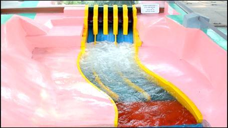
Physicalhydraulicmodelsarecommonlyusedandprovedto be indispensable tool during design stages to optimize a hydraulic structure and to make secure operation of the structure. Hydraulic design of Himalayan terrain is characterizedforitshighmountains,deepnarrowvalleys, fragile geology, and complex geological condition which involves many problems which includes Site specification problem due to topography, availability of foundation, nature of soil and rock strata etc. And problems are associatedwithcomplexflowphenomenaviz.nonuniform flowintheapproachportion,rapidlyvariedflowbecauseof complexgeometry,highvelocitiesduetohighheadsleading to cavitation damages, etc. Presently problems cannot be deal analytically and therefore they must be tackled by conductingstudiesonphysicalmodelsofthesestructures. Dissipation ofkinetic energy atthe baseof thespillway is essential for bringing the flow in d/s River to normal
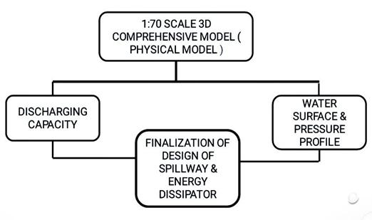
conditioninasshortofdistanceaspossible.InIndiastilling basin & ski jumped bucket are commonly used as energy Dissipators. Many safety precautions in the forms of riverbankprotectionworks,extendedtrainingwall,etc.are providedtoprotecttheriverbanksoneithersideofspillway which may prove to uneconomical in certain cases and necessitates deepexcavationfor providingthefoundation for the extended training wall that may induce hill slope destabilisationandundermining,resultinginlandslideand propertyloss.Presentstudyisbasedonrunofriverscheme in Himalayan region which is located on Punatsangchuu River in western Bhutan. The orifice spillway has been provided to pass a flood discharge (PMF) of 11500m3/s along with Glacial Lake outburst flood (GLOF) 4300 m3/s through5orificeopeningsofsize9.6mwidth×17.4mhigh withcrestlevel1166m.TheMWL/FRLisatEl.1202mand the Minimum draw down level (MDDL) is at El.1195. Hydraulic jump type stilling basin has been provided as energyDissipatortodissipateenergyformainspillway.
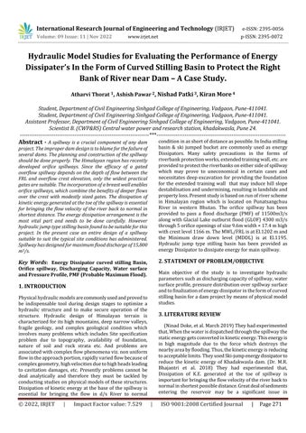
Main objective of the study is to investigate hydraulic parameterssuchasdischargingcapacityofspillway,water surfaceprofile,pressuredistributionoverspillwaysurface andtofinalizationofenergydissipatorintheformofcurved stillingbasinforadamprojectbymeansofphysicalmodel studies.
(NinadDoke,etal.March2019)Theyhadexperimented that,Whenthewaterisdispatchedthroughthespillwaythe staticenergygetsconvertedinkineticenergy.Thisenergyis in high magnitude due to the force which destroys the nearbyareabyflooding.Thus,thekineticenergyisreducing toacceptablelimits.TheyusedSki-jumpenergydissipatorto reduce the kinetic energy of Khadakwasla dam. (Dr. M.R. Bhajantri et al. 2018) They had experimented that, Dissipation of K.E. generated at the toe of spillway is importantforbringingtheflowvelocityoftheriverbackto normalinshortestpossibledistance.Greatdealofsediments entering the reservoir may be a significant issue in
International Research Journal of Engineering and Technology (IRJET) e-ISSN:2395-0056
Volume: 09 Issue: 11 | Nov 2022 www.irjet.net p-ISSN:2395-0072
Himalayan region which reduces the capacity of the reservoiranddamagesthehydropowerplants.Althoughno designprocedureswerereadilyavailablefordesigningthe energydissipatorsfororificespillways,experiencefromthe hydraulic model studies and prototype provides useful guidelines.(DhaktodeAsarametal.June2016)Theystudied to investigate the consequences of various slope of ogee spillway surface on energy dissipation. With slope of 1:1, 0.85:1, and 0.75:1 three ogee spillway models were prepared.18testrunswereappliedtoanalyzetheenergy dissipation downstream the three spillway models. (Sokchhay Heng et al. May 2012) They had studied that; Spillway is a major concern for stabilization of hydraulic structuresandtheirdownstreamchannel.Theobjectiveof this study was to select an appropriate movable riverbed material for reproducingscourholeinthe physical model andtoanalyzethecharacteristicsofitsformationusingthe selected material. (Saiful Bahri Hamzah et al. June 2016) Theyhadexperimentedthat,Physicalmodelwasutilizedto create an assessment of Batu Dam spillway, yet on make informed recommendations of its hydraulic performance and proposed alterations optimum configuration was obtained from a model scale of 1:25. Simulations with reference to various reservoir levels and discharges to analyze effects of the various flow conditions were performed.Physical hydraulicmodelsarecommonlyused during design stages to optimize a structure and to make sure a secure operation of the structure. (IS Code 10132: 1982)Thiscodehasguidelineonselectionofspillwaysand energy dissipators. (IS Code 7365: 2010) This code has guideline on Criteria for hydraulic design of bucket type energydissipators.
Forconductingmodelexperiment,itisnecessarytoobtain correctinformationfromtheprototype.Theentireoperation ofthemodeldependsontheequalityoftheprototypedata. The data would help in establishing the model prototype conformitypatternandtoenhancethepredictabilityofthe model. Generally, the following prototype data would be required for planning, construction of spillway model and conductingmodelstudies.
A model need not be made of the same materials as the prototype.Ifsurfaceoverwhichwaterflowsarereproduced inshapeandtheroughnessofthesurfaceisapproximatelyto scale(infactsmootherinthemodelthancorrespondingto prototyperoughness),themodelwillusuallybesatisfactory. Generally,theriverbedismadeupofsmoothcementplaster, spillway, non-overflow section of the dam etc. in masonry withneatplaster,spillwaypiersinteakwood,radialgatesin sheetmetalandoutletsarefabricatedintransparentPerspex. Closetolerances,particularlyincriticalareassuchasspillway crests, tangent points, energy dissipating appurtenances, modeldimensionsetc.areessential.Greatestaccuracyshould bemaintainedwheretherewillberapidchangesindirection offlowandveryhighvelocitiesoccur.Theprofilesofspillway and their allied structuresare finished to their final shape with the help of metallic templates fixed in alignment and elevation.Piezometersaregenerallyweldedtothetemplates so that their alignments are secured. The finishing of piezometersinmodelshouldbedonemeticulouslytoprevent measurement errors that would result from improper installation. Complicated curves for bell mouths of sluice spillway, breast walls, bends and transitions can be made fromPerspexwhichhasbeenheatedinovenandreshapedby pressingbetweenthemaleandfemaleconcretemolds.Itis notpossibletoreproducetheentirereservoirupstreamof spillwaynorisitnecessarytodoso.Forthespillwaylocated inthemainrivergorgewithpracticallystraightrivercourse, reproduction of about 600 to 800 m reach is usually adequate. Where the river has appreciable curvature immediately upstream of dam, or where the spillway is locatedonaflank,sothatobliquityofflowapproachingthe spillway is likely to occur, special care must be taken to incorporate these features. On the downstream, the river reaches to be incorporated would be slightly beyond the section of stage-discharge measurement in the prototype. Existinggeometricallysimilar1:70scale3-Dcomprehensive modelwasmodifiedincorporatingproposeddesignofenergy dissipatorarrangement (stillingbasin) with reducedNo.of span for spillway (5 No.) and river cross sections downstream of dam axis. The spillway was reproduced in
International Research Journal of Engineering and Technology (IRJET) e-ISSN:2395-0056
Volume: 09 Issue: 11 | Nov 2022 www.irjet.net p-ISSN:2395-0072
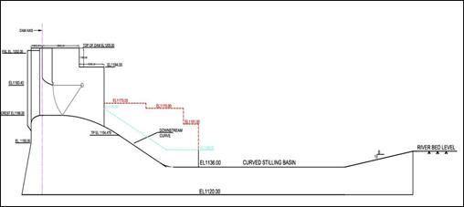
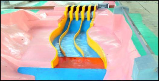
masonry,finishedwithsmoothcementplaster,andpainted withenamelpaint.Piers,breastwallandradialgateswerein PVC foam sheets. The power intake was fabricated in Perspex. The model was equipped with suitable inlet and outlet arrangements including discharge measurements. Arrangementsweremadeformeasurementofwaterlevel, andvelocities.Photos4.1.1and4.1.2showtheviewofdry model from upstream and downstream respectively. The accepted relationships of hydraulic similitude, based on Froudian criteria were used to express the mathematical relationsbetweenthedimensionsandhydraulicquantitiesof themodelandtheprototype.Thegeneralrelationsexpressed intermsofmodelscaleareasgivenbelow:
Parameter
Scale Relation
Length 1:70 Area 1:4900 Velocity 1:8.367 Discharge 1:40996.34 Time 1:8.367
Pressureinmofwaterhead 1:70 Manning’s`n’ 1:2.03
Whileexperimentation,necessaryarrangementsweremade like measurement of discharge, reservoir water levels, tail waterlevel,etc.
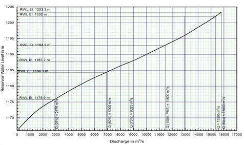
Hydraulic model studies were conducted for assessing discharging capacity of the spillway for entire range of dischargesfortheungatedoperationofspillway.Thestudies indicatedthatmaximumdischargeof15,365m3/scouldbe passed at FRL El. 1202 m. It was observed that design maximumdischargeof15,800m3/s(PMF+GLOF)couldbe passed through 5 spans fully open with upstream RWL El. 1203.3mwhereasPMFof11,500m3/scouldbepassedat RWLEl.1192.8m.Thewatersurfacefollowsthebreastwall bottomprofilefortheentirewidthfortheorificeflowregime, thusmakingtheentireheightoforificefullyeffective.Free flow was observed for discharges up to 10,500 m3/s and thereafter there was a transition to orifice flow. Graph 1 showsthedischargingcapacitycurveforungatedoperation ofthespillway.
Graph 1: Discharging Capacity Curve
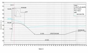
Watersurfaceprofileswereobservedalongthecenterlineof spillwayalongwithstillingbasinanddownstreamforentire range of discharges. Figures 5.2.1 to 5.2.4 show the water surfaceprofileswithungatedandgatedoperationofspillway.
International Research Journal of Engineering and Technology (IRJET) e-ISSN:2395-0056
Volume: 09 Issue: 11 | Nov 2022 www.irjet.net p-ISSN:2395-0072
Itwasobservedthattrunnionofradial gatesiswellabove uppernappeofthejetarisingfromtheorificeopeningforall the operating conditions of the spillway. Water surface elevationisbelowthetopofthetrainingwalltilltheendof stillingbasinforlowerdischarges(6,900m3/sandbelow) However,watersurfaceelevationovertoppingthetraining wall for higher discharges (discharges higher than 6,900 m3/s).Watersurfaceelevationinthestillingbasinfordesign maximumdischargeof15,800m3/sis1173m.So,theheight of the training wall may be decided considering the water surfaceprofiles,freeboardrequirementandbulkingeffectin theprototype.
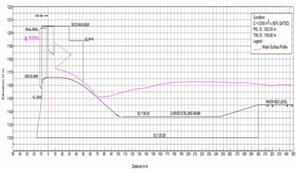
Figure 5.2.4 Water Surface Profile Q=6900 m3/s (Ungated operation of spillway)
Figure 5.2.1 Water Surface Profile Q=2875 m3/s (Gated operation of spillway)
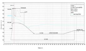
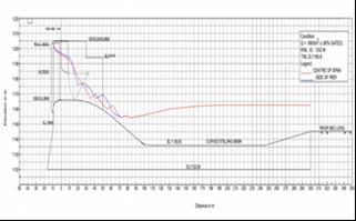
Studieswereconductedforobservingpiezometricpressures forvariousconditionsatlocationsonthebottomprofileof spillway along Centre line of spillway up to end of stilling basinandalongthesideofintermediatepierforungatedas wellasgatedoperationofthespillwaymaintainingreservoir at FRL El. 1202 m. The piezometric pressures in meter of watercolumnsonthespillwayprofileareshowninFigures 5.3.1to5.3.4.Thestudiesindicatedthatthepressuresdrop steadilyastheflowacceleratesoverthespillwaycrest.There isariseinpressureastheflowpassesoverthestillingbasin. Positive pressures were observed for the entire range of discharges;alsocorrespondingcavitationindicesobservedto be more than critical cavitation index of 0.2 for the entire length of spillway. Hence, the spillway profile is not susceptibletocavitationdamage.
Figure 5.2.2Water Surface Profile Q=2875 m3/s (Ungated operation of spillway)
Figure 5.3.1 Pressure Profile Q=2875 m3/s (Gated operation of spillway)
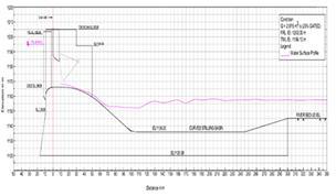
Figure 5.2.3 Water Surface Profile Q=6900 m3/s (Ungated operation of spillway)
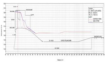
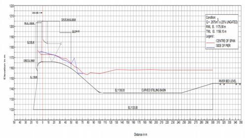
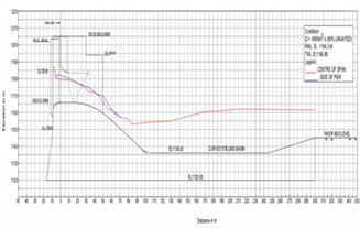
Figure 5.3.2 Pressure Profile Q=2875 m3/s (Ungated operation of spillway)
International Research Journal of Engineering and Technology (IRJET) e-ISSN:2395-0056
Volume: 09 Issue: 11 | Nov 2022 www.irjet.net p-ISSN:2395-0072
chainage60to70mand70to80m(fromdamaxis)overthe spillwayglacisfor2,875m3/supto15800m3/srespectively. Watersurfaceelevationisbelowthetopofthetrainingwall for 2,875 m3/s in the basin and the same overtops the trainingwallinthebasinfor6,900m3/sandabove.Highly turbulentandvolatileflowconditionswereobservedinthe stillingbasinforthedischargesintherangeof6,900m3/sup to15,800m3/swithwatersurfaceovertoppingthetraining wall substantially in the stilling basin area causing flow returningintothestillingbasinfromthedownstreamarea.
Figure 5.3.4 Pressure Profile Q=6900 m3/s (Gated operation of spillway)
Forungatedoperationofspillway,theflowconditionswere observed for the entire range of discharges (up to 15,800 m3/s).Frommodelstudiesitwasfoundthatthehydraulic jumpformsovertheglacisofthespillway(upstreamofthe toe) and front of the jump fluctuates (oscillates) around chainage 60 and 70 m (from dam axis) over the spillway glacis for 2,875 m3/s and up to 15800 m3/s respectively. Watersurfaceelevationisbelowthetopofthetrainingwall for 2,875 m3/s in the basin and the same overtops the trainingwallinthebasinfor6,900m3/sandabove.Highly turbulentandvolatileflowconditionswereobservedinthe stillingbasinforthedischargesintherangeof6,900m3/sup to15,800m3/s.
Figure 5.3.4 Pressure Profile Q=6900 m3/s (Ungated operation of spillway)
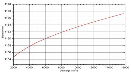
Performanceofspillwaywithstillingbasinwasstudiedfor the entire range of discharges up to the design maximum discharge of 15,800 m3/s gated and ungated operation of spillway.Thetailwaterlevelsat300mdownstreamofdam axisweremaintainedasperthetailwaterratingcurveshown inGraph2.
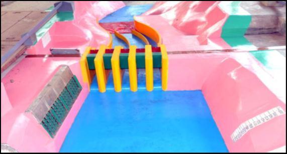
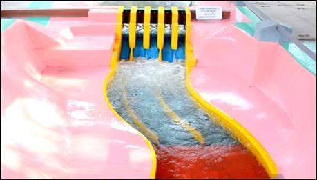
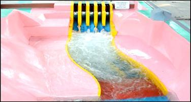
Flow conditions downstream of spillway for Q = 2,875 m3/s (Gated flow)
ForgatedoperationofspillwayatFRLEl.1202m,theflow conditionswereobservedfortheentirerangeofdischarges. From model studies it was found that the hydraulic jump forms over the glacis of the spillway (near the toe of the basin)andfrontofthejumpfluctuates(oscillates)between
Flow conditions downstream of spillway for Q = 2,875 m3/s (Ungated flow)
International Research Journal of Engineering and Technology (IRJET) e-ISSN:2395-0056
Volume: 09 Issue: 11 | Nov 2022 www.irjet.net p-ISSN:2395-0072
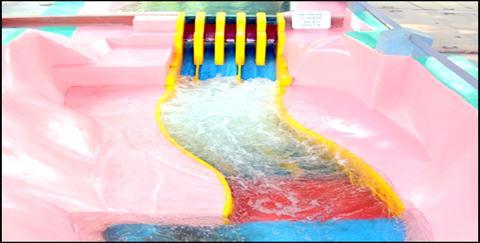
Flow conditions downstream of spillway for Q = 6,900m3/s (Gated flow)
wallsubstantiallyinthestillingbasinarea(forhigherrange of discharges, 6,900 m 3/s and above) causing the flow returningintothestillingbasinfromthedownstreamarea. Thus, existing top elevation of training wall in the stilling basin area looks inadequate. So, the height of the training wallmaybedecidedconsideringthewatersurfaceprofiles, freeboardrequirementandbulkingeffectintheprototype. Velocities at downstream of stilling basin are found to be withinacceptablelimitforvariousdischarges.Severereturn flows observed downstream of stilling basin especially at rightbankofriverforhigherdischargesmaydestabilizethe rightbankareaattheendofstillingbasin.Strengtheningof right-sideriverbanksattheendofstillingbasinishighly.
Theundertakingandprogressofthisprojectrequiredalot ofguidanceandassistancefrom manypeople,andweare extremelyprivilegedtohavethisallalongthecompletionof thisprojectreport.Allthatwehavedoneisonlyduetosuch supervisionandassistanceandwewouldnotforgettothank them.
Flow conditions downstream of spillway for Q = 6,900m3/s (Ungated flow)
1. Tranquil flow conditions were prevailing upstream of spillwayforentirerangeofdischargeswithmildvorticesin thevicinityofbreastwall.Intensityofvorticesinthewakeof the pier was slightly more for higher discharges. Tranquil flowconditionswithnoairentrainmentvortexformationin frontoftheintakeswereobservedforalltheflowconditions.
2.Dischargesof15,800m3/s(PMF+GLOF),15,365m3/s and11,500m3/scould be passedthroughall sixspans at RWL El. 1203.3 m, FRL El. 1202 m and RWL El. 1192.8 m respectively. Considering the free board above FRL, dischargingcapacityofthespillwayisadequate.
3.Positivepressureswereobservedfortheentirerangeof dischargeshence,thespillwayprofileisnotsusceptibleto cavitationdamage.Therefore,thepressuresalongtheprofile ofspillwayarefoundtobesatisfactory.
4.Studiesconductedon3-Dcomprehensivemodelindicate that performance of stilling basin is satisfactory for lower discharges (for 60% of PMF and below discharges). Trunnionofradialgatesiswellaboveuppernappeofthejet arising from the orifice opening for all the operating conditions of the spillway. Hence, location of trunnion is foundtobeacceptable.Watersurfaceelevationisbelowthe topofthetrainingwalltilltheendofstillingbasinforlower discharges (for 60% of PMF and below discharges). However,watersurfaceelevationovertoppingthetraining
Special thanks to Prof. Mrs. D. R. Vaidya, Prof. Trupti Deshmukh&Sibrat BeturkarAssistantResearchEngineer (CWPRS),forherconsistentguidanceandsupportprovided tous.Weallaregratefultobeworkingunderyourguidance. We are thankful and fortunate enough to get constant encouragement, support, and guidance from all teaching staffsofDepartmentofCivilEngineeringwhichhelpedusin successfullycompletionourprojectwork.
The authors wish to express their sincere thanks to Director,CentralWaterandPowerResearchStation,Pune fortheencouragementandpermissiontopublishtheresults. Authors also wish to thank Mr. K.T. More, Scientist ‘C’, CWPRS and all the SED division staff for the valuable guidanceanddiscussionsforthestudies.
Atlast,wewouldliketothankalltheunseenauthorsof variousarticlesontheinternet,helpingusbecomeawareof the research currently ongoing in this field and all our colleaguesforprovidinghelpandsupportinourwork..
[1] Dr. (Mrs) Bhosekar.V.V., Dr.Bhajantri M.R., Bhate R.R., (2014), “Design of Energy Dissipator for Spillways in HimalayanRegion”,ICOLDJournalVol.3,No.1
[2] Dr. (Mrs.)Bhosekar V. V., Deolalikar P. B., “Orifice SpillwayAerator:HydraulicDesign"
[3] Khatsuria, R. M. (2004), “Hydraulics of spillways and energydissipators.”,MarcelDekkerPublication,NewYork
[4]SrideviM.I.,BhateR.R.,MoreK.T.,Bhosekar.V.V.,(2012), “Design of Orifice Spillway and Energy Dissipator for
International Research Journal of Engineering and Technology (IRJET) e-ISSN:2395-0056
Volume: 09 Issue: 11 | Nov 2022 www.irjet.net p-ISSN:2395-0072
Kotlibhel-II Project’, Proceeding of National Conferences PublishinHydraulicandwaterResources(Hydro2012),IIT Bombay,India.
[5]AcharyaN.,GandhiN.H.,“ComparativeStudyofHydraulic DesignofOrificeSpillwayBetweenIS6934:1973&IS6934 (DraftCode2010)”
[6] CWPRS (March-2016), “Hydraulic Model Studies for DevsariDamSpillway,Uttarakhand,1:40scale2-Dsectional model“,TechnicalReportNo-5382[7]Dr.(Mrs)Bhosekar V.V.(2008),‘TechnicalMemorandumforHydraulicDesignof OrificeSpillways”,PublishbyCWPRS.
2022, IRJET | Impact Factor value: 7.529 | ISO 9001:2008 Certified Journal |