Experimental Analysis on Wire Arc Additive Manufacturing
Sanjeev Kumar Verma1 & Jitendra Bhashkar
2
1Research Scholar, Department of Mechanical Engineering, Harcourt Butler Technical University, Kanpur, India 2 Associate Professor, Department of Mechanical Engineering, Harcourt Butler Technical University, Kanpur, India ***
Abstract - In the present study, wire arc additive manufacturing on mild steel using conventional metal ion gas deposition is performed. After deposition, microscopic analysis is performed to check the welding defect like hot cracking and gas porosity for further process optimization. The hardness of the final product in three different stages are analyses which lie between 18 to 47 kg/mm2. After hardness analysis, mechanical testing of the specimen is analyzed in which maximum tensile and yield strength are 25.05 and 560.69MPa, respectively in the through deposition direction. It was found that layer deposition occurred in both parallel (X) and perpendicular (Y) orientations.
Key Words: Additive manufacturing, 3D printing, EDM, Microscopic, Equiaxed, Columnar, Fabrication.
1. INTRODUCTION
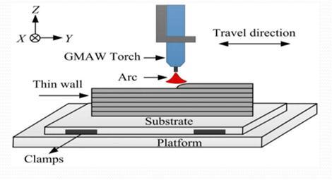
The term Additive manufacturing (AM) refers to a class of technologies used to create layered physical objects directly from computer-aided design (CAD) data [1]. These techniques allow designers to quickly prototype their designs. Such a three-dimensional and smaller model of a part or assembly, compared to a simple twodimensional drawing, gives design engineers a better idea of its dimensions and functionality. In addition to prototyping, AM techniques are used to make molds or moldinserts(high-speedtooling)andeventomakefully functional end-use parts (called rapid manufacturing). AMor3D-printinghasrevolutionizedthemanufacturing industry in everything from conceptual modeling to functionalpartsmanufacturing,andnowit'sengineering design [2, 3]. And advancing the next generation of innovation. By reducing the design and manufacturing costs of various complex components and enabling game-changing designs, AM has significantly impacted many industries. . Due to its continuous development, there is a need to acquire new manufacturing applicationsandincreasethereliability[4,5].
Oneofthelesswell-knownmetalAMtechniquesiswire arcadditivemanufacturing(WAAM),althoughithasalot of potential for 3D printing on a big scale in a variety of industries. Some of the limitations of the powder bed fusion procedure can be eliminated by using WAAM. It provides a higher deposition rate and greater build
volumeincontrasttoSLS.Thistechnologyallowsforthe quick printing of fully dense metal parts with little porosity.Itisthebestchoiceforrepairworkbecauseitis more affordable than other metal printing technologies. WAAM is a Direct Energy Deposition (DED) technology variant that 3D prints metal components using an arc welding technique. In contrast to other metal AM methods, WAAM uses an electric arc as the heat source tomeltametallicwire.Thepartisprintedonasubstrate material (a base plate) that is later removed during the finishing operation. The process is managed digitally. When the wire is melted, it is extruded onto the substrateasbeads.Thebeadscombinetoformacoating of metal as they adhere to one another. Once the metal component is reached, the procedure is repeated layer bylayer.
2. RESEARCH METHODOLOGY AND EXPERIMENTALPLAN

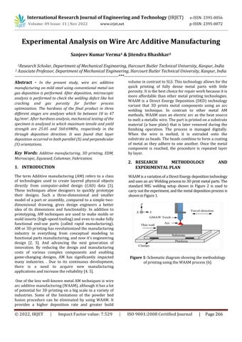
WAAMisavariationofaDirectEnergydepositiontechnology andusesanarcWeldingprocessto3Dprintmetalparts.The standard MIG welding setup shown in Figure 2 is used to carryouttheexperiment,andthemetaldepositionprocessis showninFigure1
Figure 1: Schematicdiagramshowingthemethodology ofprintingusingtheWAAMprocess[6].
e-ISSN:2395-0056
Volume: 09 Issue: 11 | Nov 2022 www.irjet.net p-ISSN:2395-0072
Table - 1: Valuesofdepositionparametersforwirearc additivemanufacturing
S No. GAP (mm) Power (kW) Wire feed rate (m/min)
Table Speed (mm/sec)
Oscillation speed (mm/sec)
1 8 2.48 4.8 1.63 5.18
2 8 2.74 5.5 1.44 5.18
3 8 2.98 5.9 1.14 5.18
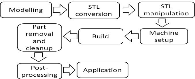
Figure 2: WorkingexperimentsetupforMWFAM Printingprocess.
Mild steel wire with a copper coating and an MS base plate were employed in the experimentation for the current study's usage of traditional MIG welding techniques. For the goals of metal wire fusion additive manufacturing, three input parameters (applied power, wire feed rate, and table speed) are chosen with three differentvaluesandanoscillationspeedthatis constant at 5.18 mm/sec. Figure 4 shows the results of the analysisofthreelayersofthemetaldepositionspecimen after it was successfully completed. Following the completionofthe depositionprocedure, thespecimenis takenfromthebaseplateusingwireEDMtoremoveany uneven surfaces, and grinding is then carried out. Using alumina powder and DI water, the grinding process is polishedafter.Afterthedepositionprocedureisfinished, the specimen is taken from the base plate using wire EDM to remove any uneven surfaces, and then the grinding process is carried out. Following the grinding process, Figure 4's polishing with alumina powder and DI water is carried out. Finally, a chemical etching procedure using 97% ethyl alcohol and 3% HNO3 is carried out. Figure 5 illustrates the analysis of the specimen grain structures after depositing, cutting, grinding,polishing,andetching.
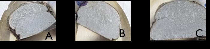
Figure 4: Specimenforviewingofmicroscopicand atomicmicroscopicstructures.
Table -2: Microscopicviewdataof3Dprintedspecimen threelayers
S. No. Gap (mm) Current (Amp) Voltage (V) Table Speed (mm/sec) Remarks
1. 8 110 22.6 1.24 B
2. 8 121 22.6 1.24 A
3. 8 132 22.6 1.24 C
Figure 3: Experimentalprocedureforwirearcadditive manufacturing.
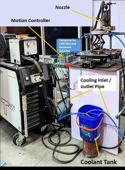
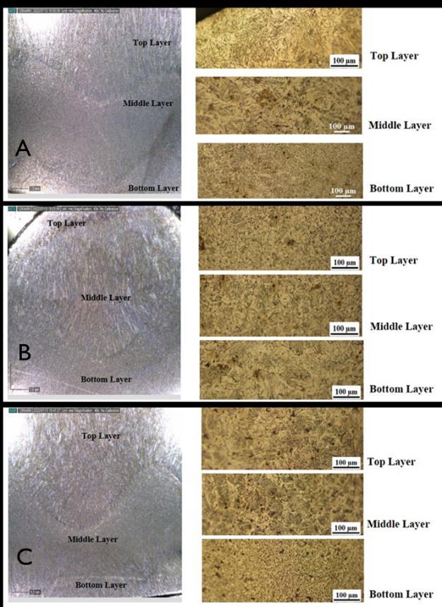
Figure 5: (A,B&C)Microscopicviewof3dprinted specimenthreelayerssegments.
e-ISSN:2395-0056 Volume:
3.1. Materials
The materials selected for this work included a support plate in EN-8, supplied in the T6 condition. The dimensions were 20 mm in thickness and 154 mm in diameter. Thewirewasa 1.2mmdiametersolidwireof copper coated solid wire conforming AWS class of SFA 5.18 ER70S-6 and is frequently used in the welding of EN-8 for structural applications. Its nominal chemical compositioninweightpercentageisoutlinedinTable3.
Table - 3: Nominalchemicalcompositionoftheselected SFA5.18ER70S-6wire.
C Mn Si S P Cu 0.060.14 1.401.60 0.80-1.0 0.025 max 0.025 max 0.50 max
3.2. LayerDeposition
An experimental setup for wire arc additive manufacturing is demonstrated in Figure 2. For experimental purposes, a EWM Phoenix 401 MIG welding power source. Zero grade CO2 gas used for shielding.
The basic welding parameters for metal fusion wire additivemanufacturingthatareusedaretabulatedinthe table. The parameters are chosen in such a way that stable deposition at lower heat is performed for edge layers.
The flange is made up of 3 beads in total, all of which were deposited in the same direction and spaced 5 mm apart. Due to an unexpected welding pause, Figure 5 shows an uneven surface halfway through one of the passes.Withthesameconditions,theremainingportion ofthepasswasinstantlydeposited.
3.3 Testing and characterization
In order to perform Rockwell hardness measurementsandinspectforpotentialwelddefects,the additive manufacturing component was put through tensile testing with samples oriented in three different
p-ISSN:2395-0072
directions, including parallel to the deposition/welding direction (X), perpendicular to the direction of the weld (Y), and through the thickness (Z). These were sliced to look at the cross sections in both the horizontal and vertical directions. Three different types of treatments were performed for specimens. To create contrast between the weld metal, the heat-affected zone (HAZ), and the support plate, the pieces were first ground and polished before being etched in ethanol and nitric acid solution. In the wake of this preparation, the hardness wasassessed.
4. RESULTANDDISCUSSION
4.1. Microscopicinspection
After three layer of metal deposition, a microscopic visual inspection is perform to analyses the grain structureofsolidifiedsurfaceareshownintheFigure5. During the grain analysis different type of grain structuresarefound.
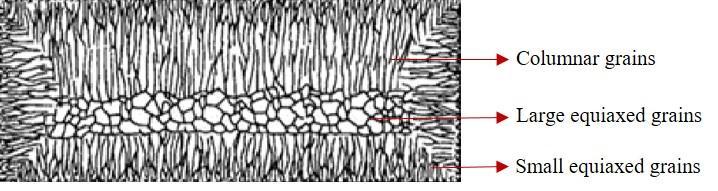
After fabrication, a microscopic visual inspection is performed to check the different welding defects, like welding creak and porosity on the surface. Due to following thegrain boundary,the welding crack present on the surface is an intergranular type. Most of the welding cracks are available in the high-temperature zone where equiaxed grain boundaries are present. These all cracks are hot cracks and developed at the grainboundaryduetothelowmeltingphase.Duringthe thermalweldcycleofcoolinglessgrainboundarycannot handle the tensile stresses, and these hot cracks are generated[8].
Porosityinthemanufacturedcomponentisthemain concern in the additive manufacturing process, affecting weldments' fatigue life [9]. Published results reveal that porosity may have a significant effect on the fatigue life of weldments. The main cause of porosity is moisture present in the wire or shielding gas. Both oxygen and nitrogen should be avoided as components of the shielding gas in WAAM because similar to hydrogen; they may be detrimental to the characteristics of aluminumwelds.
4.2. Tensile properties
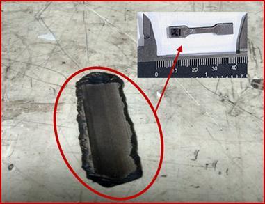
A tensile testing specimen of length is 32 mm prepared asshowninFigure7.ThesampleAhasameanyieldand tensile strength of 25.05 and 387.40 MPa, sample B has 21.23 and 513.32 and sample C have 19.67 and 560.28 MParespectively.Thegraphicalrepresentationoftensile testing for all three sample are represented in Figure 8. When the specimen was oriented parallel or perpendicular to the direction of layer deposition, the ductility was high. The area reduction has decreased to
International Research Journal of Engineering and Technology (IRJET) e-ISSN:2395-0056
Volume: 09 Issue: 11 | Nov 2022 www.irjet.net p-ISSN:2395-0072
30% for samples taken in the through-thickness direction. It was determined that the Young's modulus ranged between 18.52 and 20.25 GPa. The strength levels produced in this work are greater than those in prior published works for Al-6.4% Mg, which has a slightly higher Mg content than commercial 5183 wire [10,11].
Table - 4: Hardnesstestingresultsfordifferentsample.
Points (Top to Bottom) A (HRD) B (HRD) C (HRD)
Top 25 32 30 27 30 44 23 28 29 Middle 29 30 29 31 32 47 25 30 28 Bottom 21 28 27 28 30 29 18 29 27
Figure 8: Tensilestress(MPa)vstensilestrain(%)for allthreesample.
4.3. Hardness
The hardness of different samples is measured at different locations from the bottom to the top of the sample, as shown in Figure 9 and tabulated in Table 4. The hardness value for sample A varies from 21 to 32 kg/mm2; for sample B, it is 27 to 47 kg/mm2, while for sample C, hardness values vary from 18 to 30 kg/mm2. These hardness value levels are lower than those found by Ericsson et al. [12] in the heat-affected zone, which variesbetween60and70kg/mm2[13,14]
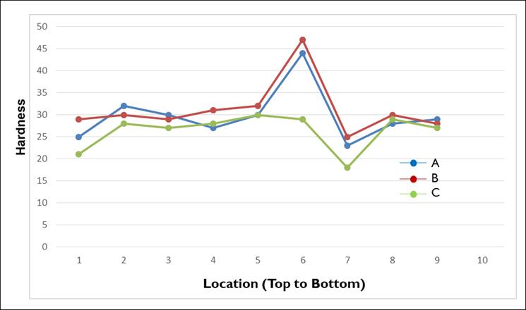
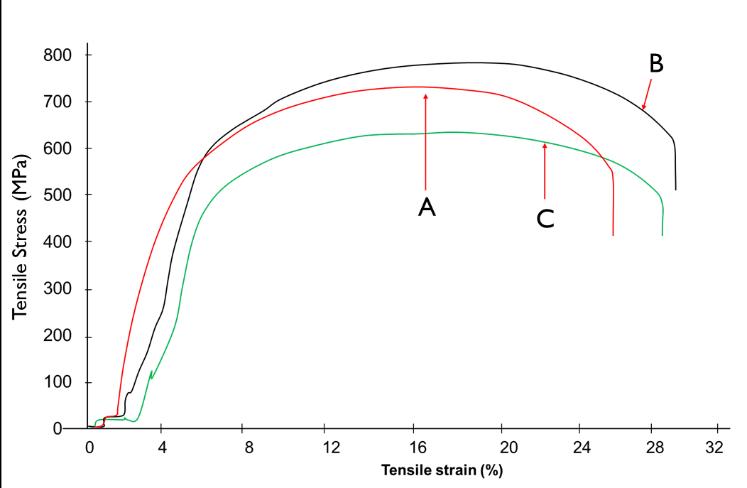
Figure 9: Variationinthehardnessatdifferentlocation ofspeciman
5. CONCLUSION
In the present study Copper coated solid wire conforming AWS class of SFA 5.18 ER70S-6 is used on mild steel support plate is used to performed WAAM process.Thefollowingworkisconcludedasfollows:
• Alongwiththe usual porosity,multilayer deposition caused some cracking in warmed weld metals from laterpasses.
• In the tensile testing of specimen, the yield and tensile strength of 320 and 155MPa is obtained respectively.
• Hardness of three different specimen are measured afterMWFAMprocesswhichisforsampleAisvaries from 21 to 32 kg/mm2, for sample B it is 27 to 47 kg/mm2 whileforsampleChardnessvaluesisvaries from18to30kg/mm2 .
REFERENCES
1. Karayel, E., Y.J.J.o.M.R. Bozkurt, and Technology, Additive manufacturing method and different welding applications. 2020. 9(5): p. 1142411438.
2. Horgar, A., et al., Additive manufacturing using WAAMwithAA5183wire.2018.259:p.68-74.
International Research Journal of Engineering and Technology (IRJET) e-ISSN:2395-0056
Volume: 09 Issue: 11 | Nov 2022 www.irjet.net p-ISSN:2395-0072
3. Kruth, J.P., et al., Binding mechanisms in selective laser sintering and selective laser melting.2005.
4. Khan, F.H.J.O.J.o.C., Chemical hazards of nanoparticles to human and environment (a review).2013.29(4):p.1399.
5. Ding,D.,etal.,Wire-feedadditivemanufacturing of metal components: technologies, developmentsandfutureinterests.2015.81(1): p.465-481.
6. Olakanmi, E.O., R. Cochrane, and K.J.P.i.M.S. Dalgarno, A review on selective laser sintering/melting(SLS/SLM)ofaluminiumalloy powders: Processing, microstructure, and properties.2015.74:p.401-477.
7. Bower,T.andM.J.A.M.S.T.Flemings,Structureof dendritesatchillsurfaces.1967.239(10).
8. Mousavi, M., et al., Effect of scandium and titanium–boron on grain refinement and hot crackingofaluminiumalloy7108.1999.4(6):p. 381-388.
9. Kecsmar,J.andR.J.J.o.s.p.Shenoi,Somenoteson theinfluenceofmanufacturingonthefatiguelife of welded aluminum marine structures. 2004. 20(03):p.164-175.
10. Geng, H., et al., Geometric limitation and tensile properties of wire and arc additive manufacturing 5A06 aluminum alloy parts. 2017.26(2):p.621-629.
11. Dutra, J.C., et al., Metallurgical characterization of the 5083H116 aluminum alloy welded with the cold metal transfer process and two different wire-electrodes (5183 and 5087). 2015.59(6):p.797-807.
12. Ericsson, M. and R.J.I.j.o.f. Sandström, Influence of welding speed on the fatigue of friction stir welds,andcomparisonwithMIGandTIG.2003. 25(12):p.1379-1387.
13. Babu, N.K., et al., Influence of titanium–boron additions on grain refinement of AA6082 gas tungstenarcwelds.2012.40:p.467-475.
14. Babu, N.K., et al., Microstructural characterization and grain refinement of AA6082 gas tungsten arc welds by scandium modifiedfillers.2012.137(2):p.543-551.