International Research Journal of Engineering and Technology (IRJET) e-ISSN:2395-0056

Volume: 09 Issue: 11 | Nov 2022 www.irjet.net p-ISSN:2395-0072
International Research Journal of Engineering and Technology (IRJET) e-ISSN:2395-0056
Volume: 09 Issue: 11 | Nov 2022 www.irjet.net p-ISSN:2395-0072
 Dr. S. B. Borghate
1 ,
Mayank Kale21Associate Professor, Dept. of Applied Mechanics, VNIT Nagpur, 440010.
2M. Tech student, Dept. of Applied Mechanics, VNIT Nagpur, 440010. ***
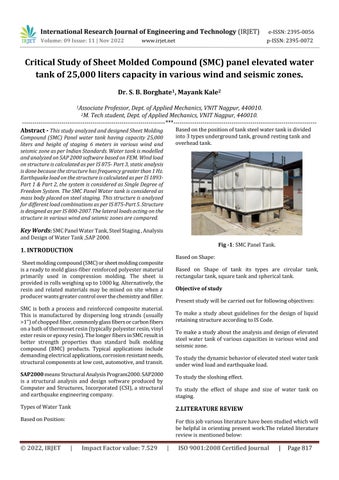
Abstract - Thisstudy analyzed and designed Sheet Molding Compound (SMC) Panel water tank having capacity 25,000 liters and height of staging 6 meters in various wind and seismiczoneasperIndianStandards.Watertankismodelled andanalyzedonSAP2000softwarebasedonFEM.Windload onstructureiscalculatedasperIS875-Part3,staticanalysis isdonebecausethestructurehasfrequencygreaterthan1Hz. EarthquakeloadonthestructureiscalculatedasperIS1893Part 1 & Part 2, the system is considered as Single Degree of Freedom System. The SMC Panel Water tank is considered as mass body placed on steel staging. This structure is analyzed fordifferentloadcombinationsasperIS875-Part5.Structure isdesignedasperIS800-2007.Thelateralloadsactingonthe structure in various wind and seismic zones are compared.
Key Words: SMCPanelWaterTank,SteelStaging,Analysis andDesignofWaterTank,SAP2000.
Sheetmoldingcompound(SMC)orsheetmoldingcomposite isareadytomoldglass-fiberreinforcedpolyestermaterial primarily used in compression molding. The sheet is providedinrollsweighingupto1000kg.Alternatively,the resin and related materials may be mixed on site when a producerwantsgreatercontroloverthechemistryandfiller. SMC is both a process and reinforced composite material. This is manufactured by dispersing long strands (usually >1”)ofchoppedfiber,commonlyglassfibersorcarbonfibers onabathofthermosetresin(typicallypolyesterresin,vinyl esterresinorepoxyresin).ThelongerfibersinSMCresultin better strength properties than standard bulk molding compound (BMC) products. Typical applications include demandingelectricalapplications,corrosionresistantneeds, structuralcomponentsatlowcost,automotive,andtransit.
SAP2000 meansStructuralAnalysisProgram2000.SAP2000 is a structural analysis and design software produced by Computer and Structures, Incorporated (CSI), a structural andearthquakeengineeringcompany.
BasedonPosition:
Basedonthepositionoftanksteelwatertankisdivided into3typesundergroundtank,groundrestingtankand overheadtank.
Based on Shape of tank its types are circular tank, rectangulartank,squaretankandsphericaltank.
Presentstudywillbecarriedoutforfollowingobjectives:
To make a study about guidelines for the design of liquid retainingstructureaccordingtoISCode.
Tomakeastudyabouttheanalysisanddesignofelevated steel watertank of various capacitiesinvarious windand seismiczone.
Tostudythedynamicbehaviorofelevatedsteelwatertank underwindloadandearthquakeload.
Tostudythesloshingeffect.
To study the effect of shape and size of water tank on staging.
Forthisjobvariousliteraturehavebeenstudiedwhichwill be helpful in orienting present work.The relatedliterature reviewismentionedbelow:
International Research Journal of Engineering and Technology (IRJET) e-ISSN:2395-0056
Volume: 09 Issue: 11 | Nov 2022 www.irjet.net p-ISSN:2395-0072
El Damatty et al., (1998) Conical steel vessels, having an higher cylindrical segment and supported by using a bolstered concrete shaft, are becoming broadly used for water containment in elevated tanks. However, the contemporarycodesofpracticeforwaterstructuresinNorth America do no longer consist of any rational method for designingsuchvessels.Inthislookat,asimpleandrational design system that considers instability, yielding, large deformations,geometricimperfections,andresidualstresses isdevelopedforthosehydrostaticallyloadedmetallicvessels.
Tom H. Hale (2004) This paper describes the seismic evaluationandlayoutstrategiesusedfortheseismicimprove of an present 3,000,000 gallon (11,355,000 liters) steel improvedwatertanksupportedbyametallicframeworkin Sacramento, California. The preliminary seismic upgrade designconsistedofabaseisolationgadget.Thefinalseismic improvedesigncarriesapassivepowerdissipationmachine inside the braces of the framework to create a friction dampedbracedframe.
Norris et al.,(2014) Elevated water tanks are normally placed at better elevations within a particular geographic place.Thelocationsandtopofthosestructuresoftenmakes them ideal for siting wi-fi and mobile communications antennas.Theeffectofthisexerciseonthelong-timeperiod serviceabilityoverallperformanceoftheprimaryshapeisn't cleanandwill beanimportantattentiondeservingfurther evaluation.
Jena et al., (2016) A meshfree molecule approach, to be specific moving molecule semi-certain (MPS) technique is utilizedtoexaminethesloshingconductinatosomedegree filledfluidcompartment.Thelegitimacyofthemathematical model is checked by looking at the sloshing movement in tanks going through sinusoidal and seismic tremor excitations with the distributed outcomes. An exhaustive investigation of seismically invigorated vicious sloshing movementandwaveinfluenceutilizingamoleculetechnique, notrevealedinopenwriting,weretakenupinthecurrent review.
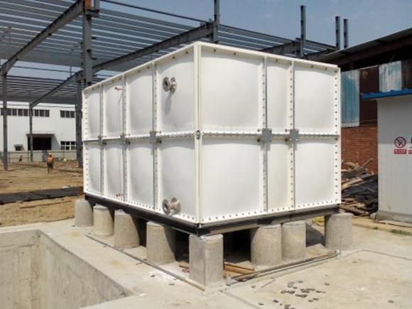
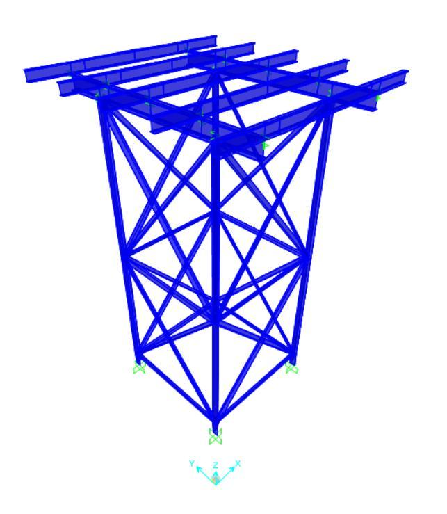
The SMC Panel Water tank is modelled as mass acting on bearers. The load is applied as uniformly distributed load. Thedimensionofthetankis3mx3mx3m.Thedimension of the tank is given by SMC Panel Company. The steel Isectionisusedasbearerandlowerbeam. Forcolumnsand bracings angle section is used. The joints assigned is fixed joints as it assumed to be rigid connections. The plan and elevationisshowninFigure2.
4.0 4.0
Fig -2:ElevationandPlanofTank.
Fig -3:MathematicalModellingofSMCPanelTank
International Research Journal of Engineering and Technology (IRJET) e-ISSN:2395-0056
Volume: 09 Issue: 11 | Nov 2022 www.irjet.net p-ISSN:2395-0072
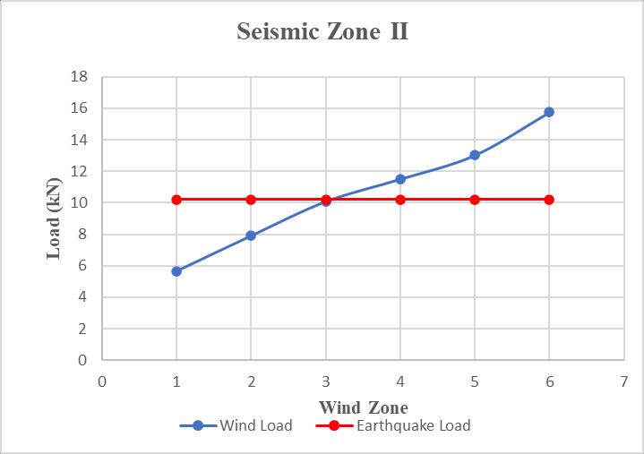
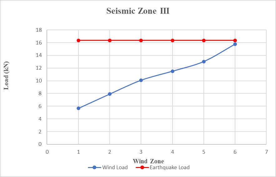
3.2 Governing Lateral Load Comparison.
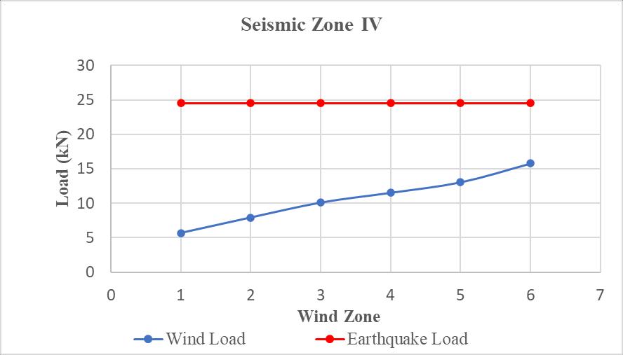
Chart -4:ComparisonofLateralloadinSeismiczoneV
Chart -1: ComparisonofLateralloadinSeismiczoneII
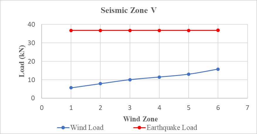
Chart -2:ComparisonofLateralloadinSeismiczoneIII
TheloadcombinationsareassignedasperIS875. 1. 1.2(DL-EQX) 2. 1.2(DL+EQY) 3. 1.2(DL-EQY) 4. 1.2(DL+EQX) 5. 1.5(DL-EQX) 6. 1.5(DL+EQY) 7. 1.5(DL+EQY) 8. 0.9DL-1.5EQX 9. 0.9DL+1.5EQY 10. 0.9DL-1.5EQY 11. 0.9DL+1.5EQX 12. 1.2(DL+WLX) 13. 1.2(DL+WLY) 14. 1.2DL+0.6WLX 15. 1.2DL-0.6WLX 16. 1.5(DL+WLX) 17. 1.5(DL+WLY) 18. 0.9DL+1.5WLX 19. 0.9DL+1.5WLY.
Chart -3:ComparisonofLateralloadinSeismiczoneIV
2022, IRJET | Impact Factor value: 7.529 | ISO 9001:2008 Certified
International Research Journal of Engineering and Technology (IRJET) e-ISSN:2395-0056
Volume: 09 Issue: 11 | Nov 2022 www.irjet.net p-ISSN:2395-0072
ThewatertankisdesignedinSAP2000forearthquakeload with considering wind load of different wind speed. The result of these 6 wind zones are shown in Table 1. Computationalresultsincludebendingmomentsofmembers forallloadcombinations.
Table-1: MaximumMembersAxialLoadsforvariouszones (kN).
Member
Computationalresultsincludebendingmomentsofmembers forallloadcombinations.
Table-3: MaximumMembersAxialLoadsforvariouszones (kN). Member
Wind Zone 1 Vb= 33m/s
2 Vb= 39m/s
3 Vb= 44m/s
4 Vb =47 m/s
5 Vb= 50m/s
6 Vb =55 m/s
Wind Zone 1 Vb =33 m/s
2 Vb =39 m/s
3 Vb =44 m/s
4 Vb =47 m/s
5 Vb =50 m/s
6 Vb =55 m/s
Column -134.5 -134.4 -134.4 -134.4 -138.7 -139.2 Hori. Bracing 3.2 3.2 3.2 3.24 3.3 3.4 Incl Bracing -14.1 -14.12 -14.12 -14.41 -14.15 -14.60
(+=Tension,-=Compression)
ThemembersaredesignedasperIS800-2007bytakinginto considerationthemaximumreactions.Thisdesignischecked onSAP2000.Thesectionsassignedformembersareshown inTable2.
Table-2: DesignSectionsforMembersasperIS800-2007. Members
Wind Zone Zone 1 Vb= 33 m/s
Column -141.4 -141.4 -141.4 -141.4 -141.4 -141.4
Hori Bracing 3.4 3.4 3.4 3.4 3.4 3.4
Incl. Bracing -15.3 -15.3 -15.3 -15.3 -15.3 -15.3 (+=Tension,-=Compression)
ThemembersaredesignedasperIS800-2007bytakinginto considerationthemaximumreactions.Thisdesignischecked onSAP2000.Thesectionsassignedformembersareshown inTable4
Table-4: DesignSectionsforMembersasperIS800-2007.
Members
Zone 2 Vb= 39 m/s
Zone 3 Vb= 44 m/s
Zone 4 Vb= 47 m/s
Zone 5 Vb= 50 m/s
Zone 6 Vb= 55 m/s Column ISA 110 110 10
Wind Zone Zone 1 Vb= 33 m/s
Zone 2 Vb= 39 m/s
Zone 3 Vb= 44 m/s
Zone 4 Vb= 47 m/s
Zone 5 Vb= 50 m/s
Zone6 Vb=55 m/s
ISA 110 110 10
ISA 110 110 10
ISA 110 110 10
ISA 110 110 12
ISA 110 110 12 Horizontal Bracing
Column ISA 110 110 12
ISA 110 110 12
ISA 110 110 12
ISA 110 110 12
ISA 110 110 15
ISA110 11015
ISA 6060 10
ISA 6060 10
ISA 6060 10
ISA 6060 10
ISA 6060 10
ISA 6060 10
ISA 6060 10
ISA 6060 10
ISA 6060 12
ISA 6060 12
ISA 6060 12
ISA 6060 12 Inclined Bracing
ThewatertankisdesignedinSAP2000forearthquakeload with considering wind load of different wind speed. The result of these 6 wind zones are shown in Table 3
Horizontal Bracing
Inclined Bracing
ISA 60 60 12
ISA 60 60 12
ISA 60 60 12
ISA 60 60 12
ISA 60 60 12
ISA 60 60 12
ISA 60 60 12
ISA 60 60 12
ISA 65 65 8
ISA 65 65 8
ISA65 65 8
ISA65 65 8
ThewatertankisdesignedinSAP2000forearthquakeload with considering wind load of different wind speed. The result of these 6 wind zones are shown in Table 5
International Research Journal of Engineering and Technology (IRJET) e-ISSN:2395-0056
Computationalresultsincludebendingmomentsofmembers forallloadcombinations.
Table-5: MaximumMembersAxialLoadsforvariouszones (kN).
Table-7: MaximumMembersAxialLoadsforvariouszones (kN).
Member
Member
Wind Zone 1 Vb =33 m/s
Wind Zone 1 Vb= 33m/s
2 Vb =39 m/s
3 Vb =44 m/s
4 Vb =47 m/s
5 Vb =50 m/s
6 Vb =55 m/s Column -150.6 -150.6 -150.8 -150.8 -150.8 -150.8 Hori Bracing 3.6 3.6 3.6 3.6 3.6 3.6 Incl Bracing -16.8 -16.8 -16.8 -16.8 -16.9 -16.9 (+=Tension,-=Compression)
ThemembersaredesignedasperIS800-2007bytakinginto considerationthemaximumreactions.Thisdesignischecked onSAP2000.Thesectionsassignedformembersareshown inTable6.
Table-6: DesignSectionsforMembersasperIS800-2007.
Members
2 Vb =39 m/s
3 Vb =44 m/s
4 Vb =47 m/s
5 Vb =50 m/s
6 Vb =55 m/s
Column -164.4 -164.4 -164.5 -164.5 -164.5 -164.5 Hori. Bracing 3.9 3.9 3.9 3.24 3.9 3.9 Incl Bracing -19.2 -19.2 -19.2 -19.5 -19.5 -19.5 (+=Tension,-=Compression)
ThemembersaredesignedasperIS800-2007bytakinginto considerationthemaximumreactions.Thisdesignischecked onSAP2000.Thesectionsassignedformembersareshown inTable8.
Table-8: DesignSectionsforMembersasperIS800-2007.
Members
Wind Zone Zone 1 Vb= 33 m/s
Zone 2 Vb= 39 m/s
Zone 3 Vb= 44 m/s
Zone 4 Vb= 47 m/s
Zone 5 Vb= 50 m/s
Zone 6 Vb= 55 m/s Column ISA 110 110 15
ISA 110 110 15
ISA 110 110 15
ISA 110 110 15
ISA 130 130 10
ISA 130 130 10 Horizontal Bracing
ISA 65 65 8
ISA 65 65 8
ISA 65 65 8
ISA 65 65 8
ISA 65 65 8
ISA 65 65 8
ISA 65 65 8
ISA 65 65 8
ISA 65 65 10
ISA 65 65 10 Inclined Bracing
ISA 65 65 10
ISA 65 65 10
ThewatertankisdesignedinSAP2000forearthquakeload with considering wind load of different wind speed. The result of these 6 wind zones are shown in Table 7 Computationalresultsincludebendingmomentsofmembers forallloadcombinations.
Column ISA 130 130 10
Horizontal Bracing
Inclined Bracing
ISA 65 65 10
ISA 65 65 10
Zone 2 Vb= 39 m/s
ISA 130 130 10
ISA 65 65 10
ISA 65 65 10
Zone 3 Vb= 44 m/s
ISA 130 130 10
ISA 65 65 10
ISA 65 65 10
Zone 4 Vb= 47 m/s
Wind Zone Zone 1 Vb= 33 m/s
ISA 130 130 10
ISA 65 65 10
ISA 65 65 10
Zone 5 Vb= 50 m/s
ISA 130 130 12
ISA 75 75 8
ISA 75 758
Zone6 Vb=55 m/s
ISA 130 130 12
ISA75 75 8
ISA75 75 8
Volume: 09 Issue: 11 | Nov 2022 www.irjet.net p-ISSN:2395-0072 © 2022, IRJET | Impact Factor value: 7.529 | ISO 9001:2008 Certified Journal | Page821
AftertheanalysisanddesignofSMCwatertankof25,000 literscapacityand6mheightofstagingfordifferentwind speedandearthquakezones,someconclusionsaremade.The conclusionsfromthestudyareasfollows
1. ForEarthquakezoneII,forwindspeedupto44m/s earthquakeforceisgoverning.Forwindspeedabove 44m/swindforceisgoverning.
International Research Journal of Engineering and Technology (IRJET) e-ISSN:2395-0056
Volume: 09 Issue: 11 | Nov 2022 www.irjet.net p-ISSN:2395-0072
2. ForEarthquakezoneIII,IVandVearthquakeforceis governingirrespectiveofwindzone.
3. After providing section for the column as per maximum reaction obtained by envelope combination,columnfailsindesign.So,wehaveto provideheaviersectionforcolumnsection.
[1] Arya, A.S., and J.L. Ajmani.2001. “Design of Steel Structures.”Roorkee,India.
[2] Cui Y., M. Nakashima and T. Hitaka.2008. “Using SteelFiberReinforcementCementitiousComposite (SFRCC) in shallow Embedded Column Base.” J. Struct. Eng. 6:364-376. https://ascelibrary.org/doi/10.1061/41142%2839 6%2930
[3] ElDammatty,A.A.,M.El-AttarandR.M.Korol.1998. “Simple Design Procedure for Liquid-Filled Steel Conical Tanks.” J. Struct. Eng. 125:875-890. https://ascelibrary.org/doi/10.1061/%28ASCE%29 0733-9445
[4] Hale, T.H. 2004. “Seismic Upgrade of A 3MG Steel Elevated Water Tank.” J. Struct. Eng. https://ascelibrary.org/doi/abs/10.1061/40492%28 2000%29114
[5] Hazim, S. 2012. “Stress Concentration in Elevated Steel Storage Tanks and Silos.” J. Struct. Eng.12:20462057.https://ascelibrary.org/doi/10.1061/9780784 412367.180.
[6] IS (Indian Standard).1984. “Code of Practice for General Construction in steel.” IS 800-1984. New Delhi,India.
[7] IS(IndianStandard).2007.“GeneralConstructionin steel – Code of Practice.” IS 800-2007. New Delhi, India.
[8] IS(IndianStandard).2014.“CriteriaforEarthquake Resistant Design of Structures.” IS 1893(Part 2)2014. NewDelhi,India.
[9] IS (Indian Standard).2015. “Design Loads (Other thanEarthquake)forBuildingsandStructures-Code ofPractice.”IS875(Part3)-2015. NewDelhi,India.
[10] Jena,D.andK.C.Biswal.2017.“ViolentSloshingand WaveImpactinaSeismicallyExcitedLiquid-Filled Tank: Meshfree Particle Approach.” J. Eng Mech. 25:07339399.https://ascelibrary.org/doi/10.1061/%28ASC E%29EM.1943-7889.0001364
[11] Mahamid, M., T. Brindley, N. Abraham and N. Triandfilou.2018. “Material Deterioration FitnessFor-Service Analysis and Repair of a Steel Tank.” Forensic Eng.18:545556.https://ascelibrary.org/doi/10.1061/97807844 82018.053
[12] Norris,J.T.andK.A.Grimmelsman.2014.“Structural IdentificationofanElevatedWaterTank.” J. Struct. Eng.14:27442753.https://ascelibrary.org/doi/10.1061/9780784 413357.240
[13] SintexIndustriesLimited.2022.“SintexSMCPanel Tanks.”
[14] Yuan,Q.,S.BatemanandL.Ye.2005.“Mechanicaland Crash Behaviour of Sheet Moulding Compound Materials.” J. Adv. Comp. Lett.14:7-14. https://publication/287401714_Mechanical_and_Cr ash_Behaviour_of_Sheet_Moulding_Compound_Mate rial
[15] Zhao,X.L.,R.Al-MahaidiandS.Rizkalla.2014.“Effect ofDynamicLoadingandEnvironmental Conditions ontheBondbetweenCFRPandSteel:State-of-theArt Review.” J Comp. Constr.125:10900268.https://ascelibrary.org/doi/10.1061/%28ASC E%29CC.1943-5614.0000419.
2022, IRJET | Impact Factor value: 7.529 | ISO 9001:2008 Certified Journal | Page822