International Research Journal of Engineering and Technology (IRJET) e-ISSN:2395-0056

Volume: 09 Issue: 11 | Nov 2022 www.irjet.net p-ISSN:2395-0072
International Research Journal of Engineering and Technology (IRJET) e-ISSN:2395-0056
Volume: 09 Issue: 11 | Nov 2022 www.irjet.net p-ISSN:2395-0072
1Faculty of Technology and Education, Helwan University, Egypt, 2 Electricity Teacher, Industrial Secondary School, Menoufia, 3 Engineering Department, Faculty of Engineering, Menoufia University, Egypt, 4Faculty of Technology and Education, Helwan University, Egypt. ***
Abstract – The inverter based small networks connected in parallel, the inverters can operate in connected or separate network mode, and in the connected mode, the set points for each inverter are created by processing data on the active output powers and placing all the inverters in a principal controller basedonthe neededoutput power ratios. Here,two proposed power-sharing structures are used to provide a fast and accurate dynamic response to a low circulating current between parallel inverters and the ability to adapt to the required changes in the system to make it stable and make each inverter give its full capacity to the loads. In this article, two different types of system control are used to share energy through electrical inverters. The droop control and virtual impedance are used, and each system improves the performance of the control in a better way to share the load energy. The proposed energy-sharing control systems strategies have been validated using mat-lab/Simulink simulation results
Keywords: Droop Control; Micro-grid control; Power Sharing; parallel inverter; line impedance.
The integration of several distributed energy resources (DERs)thatarelinkedinparallel,suchasparallelinverters in micro-grid operation, is necessary to meet the growing needforlarge-scalepowersupplywithhighdependability [1].Advancedcontroltechniquesarenecessaryforparallel inverterstooperateproperly.Manyofthesemethodswere first presented decades ago, and they are still developing today [2]. a frequency-voltage droop approach is a wellrecognizedwidelyused,andsuccessfulmethodforoperating parallel inverters [3]. this method simulates how a largescalepowersystemworksbyusingapre-setdroopfeature that links improvements in generator speed and output activepower.Thistechnologyisknownaswirelesscontrol sincenocommunicationisnecessarybetweentheinverters makingit simpletodeploy anddependable[4].But,ithas variousdrawbacksthatmighthinderitseffectiveness.Some ofitslimitationswerejustasdescribedinthefollowing:its frequency and amplitude differences are load dependent, resulting in poor load voltage regulation performance; an inherent trade-off between voltage regulation and power
sharingbetweeninverters,andimpedancemismatchamong invertersaffectspowersharingperformance[5].
Manyimprovementshavebeenproposedinrecentyearsto increasetheeffectivenessofthedroopcontrolapproachin order to satisfy the rising needs of micro-grids. Modified droop [6-8], adaptive droop [9-11], mixed droop [12-14], and interconnected droop working principle [15-18] are someofthesuggestedchanges.Astandarddroopsystemis given a boost in transient responsiveness in [6] by the addition of power derivative-integral terms. Selecting the propercoefficientsforthederivativeterm,however,inorder toguaranteestablesystemperformance,ischallenging.The authorsof[11]suggestedcombiningstaticdroopfeatures withanadaptivetransientdroopfunctiontoenableactive dampening of power oscillations. The authors did not, however, provide experimental confirmation for this method.Theauthorsof[16]presentedanenhanceddroop method that employs web-based limited bandwidth connection to enhance load-sharing ability. This performancerealizesefficientelectricpower-sharingwith themicrogrid.Adroopcontrolwithanoptimizationsystem is presented in [13]. It uses particle cloud optimization to optimizethe(v-f)constant.Itshowsrespectableactiveand reactive power sharing in simulation, but there is no hardwareconfirmation.
Inverterslinkedinparallelhavelatelycometounderstand thatexchangingcertaininformationamongthemmayhelp accomplishgreatcurrentsharingandvoltagemanagement inaparallelsystem.Activeload-sharingmethodsareafew examples of control strategies that make use of communication between parallel inverters. These include theaveragecurrentconfiguration[21,22],themaster-slave system[19,20],andthesphericalcurrenttechnique.
Inthecircular-chaincurrentapproach,succeedinginverter modules follow the current of the preceding inverter to achieveequalcurrentcirculating.Thefundamentalflawwith thisstrategyisthatitsignificantlyreliesoncommunications, whichintroducessubstantialuncertaintiesintothesystem. Themaster/slaveapproachemploysoneinvertertocontrol theamplitudeandfrequency,whiletheremaininginverters serve as slaves that inject currents. All of the micro grid's inverters participate in the typical current-sharing mechanism,whichregulatesvoltage,frequency,andcurrent.
International Research Journal of Engineering and Technology (IRJET) e-ISSN:2395-0056
Volume: 09 Issue: 11 | Nov 2022 www.irjet.net p-ISSN:2395-0072
Inparticular,theinvertercurrentinjectionaveragedovera common bus is taken into account as a reference for each modulewhendeterminingtheaveragecurrentdata.
Active load sharing approach has unique benefits and drawbacks. There are many different ways to solve the problem,fromcommunicationtotechniquesthatneedless communication.Toavoidoverheatingandmaintainalonger lifespan,someapplicationshavestrictloadingrequirements for the inverters, and correct active and reactive power sharing is essential. These implementations will be made easierbyhavingtheabilitytochangethepowerreferences while maintaining precise sharing and damped responsiveness. Therefore, a control scheme that is adaptable, trustworthy, and has strong voltage stability, currentsharing,anddecreasedcurrentflowingfeaturesis preferred. It should also have minimal reduced communications and be resistant to communication overhead.
In this article, a comparison will be made between two different power-sharing technologies. In this paper, a comparisonwillbemadebetweentwootherpower-sharing techniques(droopcontrollerandvirtualimpedance),which usesfuzzylogic,andnecessarilyrequiresalow-bandwidth connectiontoacentralcontroller.Alloftheparallelinverters that are connected to the central control unit send information about their active and reactive power, and it usesthatdatatocalculateeachinverter'sactiveandreactive power references. Based on a particular ratio of output powertoeachinverter,thesereferencesarecomputed.This informationisusedbyeachinvertertomodifythevoltage andamplitudereferencephaseinrelationtothesharedAC vector in order to achieve the required output power. By adjustingthephaseratherthanthefrequency,asaresult,it ispossibletoachieveeffectivefrequencyregulationwithout affectingthenatureofthevariousfiltersLCLandLCusedto sharepowerbetweeninvertersconnectedinparallelwith the grid between power and load sources for system stability.Theoveralldesignoftheinverterisshowninfigure 1.Thevoltagecontrollertransmitsmodulatedsinewavesto itsIGBTswitchingcomponents,whichbeginreceivingthem. Thesystemcontainstwosolarcellnetworks,inwhichthe maximumpowerisobtainedthrough PerturbandObserve (o&p)[33].Thetwonetworksareconnectedfromtheside oftheinverteroutput.Theinverteriscontrolledthroughthe two techniques Below is a simplified explanation of each partofthesystem.

five sections make up the structure of this term paper Section(2and3)discussesthesystemarchitectureOneof thefundamentalproblemsofparallelinvertersistherobust designofeachinverteroperatinginparallelwiththepower gridandtheproposedpower-sharingmethod,asAstability study of the proposed technologies for virtual impedance andsystemcontrolalgorithm,whichhasamaximumpower pointtrackingMPPTphotoelectriccontroller,ispresentedin
Section (4). Analysed in a mat-lab environment Simulink simulationresultsinvariableweatherconditionsareshown inSections(5)tosupportthefeasibilityandefficacyofthe proposedmethodrespectively,theconclusionsemphasize themainresultsandtheabilitytocontributetothisarticle.
Fig-1: GeneralmicrogridStructure
1.1 Photo voltaic (P.V) System
A PV module consists of several solar cells connected in seriesandparalleltoobtainthedesiredvoltage¤t outputlevelsshowninFig2.PVconsistsofaphotocurrent source��ph,diode,andinternalresistances����andRp[35,36].
Iph: Lightproducedcurrent(A).
ID:Diodesaturationcurrent(A).

Io:reversesaturationcurrentofthediode
q:electroncharge( )
K:Boltzmannconstantin1.3865×10^-23(J/K)
µ: conversionefficiency(%)
Id:currentthroughthediode
Tc: operatingtemperature(ºc)
Parasite resistivity is a component of a functional photovoltaicarray.
Due to the continued resistance of the interconnections metalgrid,pandnlayer,thereisseriesresistance
International Research Journal of Engineering and Technology (IRJET) e-ISSN:2395-0056
Volume: 09 Issue: 11 | Nov 2022 www.irjet.net p-ISSN:2395-0072
Shunt resistivity brought on by p-n connection leakage current.
A PV system is physically described in the following equations[35,36].
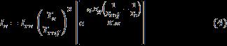
Fig-3:Schematicdiagramofboostconvertercontrol.
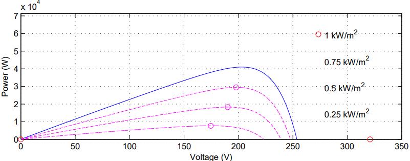
InFig.4thephoto-voltaicoutputpowerisplottedagainst the plate voltage for specific radiation. Traditional P&O technology [27,30] uses photovoltaic panels or current disruptionstocontinueoperatingandcomparesthepower ratingofthephotovoltaiccelltothepriorperturbationcycle. Features1- InitialRestorativeDynamics
2-Analog/digitalimplementation
Thesolarmodule'sefficiencyisdeterminedbydividingthe greatest amounts of electricity it can generate by solar irradiation[28].
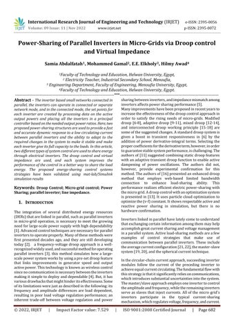
µ = (5)
Tracking the PV array's greatest peak power in order to produce the most electrical power is the crucial step for photovoltaicarrays.Thebestprocedureshouldbefollowed during the design of the PV system, and various MPPT methods can be used to ensure this [23]. It depends on irradianceandtemperature.Therearevariouslayersineach strategy.Applicationcharacteristics,includingthoseofthe mosticonicone,thehillclimbingtechniqueontheresilience oftwopoints,canhaveasignificantimpactonthechoiceof MPPT control systems, including complexity sensors, amount of digital or analogue applications, rapid convergencetraceability,andfinancialimpact.P(k),p(k-1) StartcomparingMPPTandMPPsidebyside.
The primary benefit of strategic is that it is inexpensive, simpletoimplement,doesnotrequireacontrolschemeor micro-controller,andonlyrequiresonevoltagesensor[17]. Aslongastheradiationfromthesundoesnotfluctuatetoo muchthroughouttheday,thismethodworkswell[28].
As shown in Fig.3the suggested MPPT algorithm is perturbative and controls the dc - dc converter using feedback.AboostconverterItincreasesthevoltagevalueat theexpenseofthecurrentvalueanddealswiththeconstant currentonlyandmakesacomparisonprocessbetweenthe voltageofasolarcellVpv andthevoltageinsidetheinverter
Vref
3-Minimalsoftware/hardwarerequirements.Theoperating voltage in between the PV array and the converter is perturbedbytheP&omethod.
P&OItconsistsoftwomainparts,PointA: dP/dV>0Ifthe operatingpointontheleftMPPand PointB:dP/dV<0 If the operating point on the right MPP, dP/dv = 0 At the operatingpointontheMPPTurbulentisemployedinvoltage and power measurement methods, and the high value utilizationoftheturmoildirectioniscalculatedby
P . If the polarization of a power output is positive,anextdisturbancewilltravelinsamedirectionsas the prior one. If the depolarization of a power output is negative,anextdisturbanceisinthereversedirectionasthe priorone.WhenMPPisattained,theoperationisrepeated.
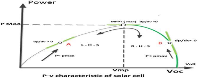
the inverter as shown in the image(5) converts dc to ac current and must be included in any micro-network that uses electrical power electronics to serve single or threephase loads consisting of high frequency solid-state electronicsand anL - LCL low-passfilteritis incharge of smoothingtheoutputwaveinordertoachieveasinusoidal signal free of harmonics the inverter has a steady current
International Research Journal of Engineering and Technology (IRJET) e-ISSN:2395-0056
input and is linked to a capacitor which stabilizes and regulatesthevoltageenergyfromsolarcellsandraisesitto the inverter the output is the ac current produced at the invertersoutputsignalsaresentbythevoltagecontrollerto the switching devices which are isolated gated bipolar transistors(IGBT) Vref andP.W.Msignalsaregeneratedin addition when the A.C signal of the power electronic switcheschangesharmonicsignalsarecreatedtheLCLfilter is widely used in conjunction with inverse networks to enhancecurrentexcellenceandsupplyoptimumsinusoidal powertoapowergridwhileminimizingharmonics.
Where istheresistanceofthevirtualimpedance,orit canbeinductiveas Where istheinductanceofthevirtualimpedanceandis the time constant of the high pass filter used to approximate the derivative in the transfer function of the idealvirtualinductance [25].
Fig -5:inverterandLCLfilter
Avoltagecontrollerloopisusedinbasicvoltagesource invertersVSItotrackthedesiredinputsignalandreduceits error and the measured output voltage. A proportional controller, Kv, is utilized in this study, backed by a feedforward loop. The feed-forward loop reduces steady-state errorwhileallowingforabroadercontrolband[1,3].
Fig.4depictsoneinverterphase.Theirinnerloopcontrollers are shown in this block diagram [12,14]. In this paper, (“VirtualImpedanceImpactonInverterControlTopologies”) This impedance mimics the behavior of an inductor or resistorintheprogram.Usingaprogrammableimpedance rather than a physical one reduces the losses and costs [19,22].Inaddition,beingprogrammablepresentsadaptive operation and increases the inverter’ s robustness against network impedance variations [23,27]. Fig. 6 shows the block diagram of the voltage controller with the virtual impedanceZv(s).
Fig -6:Themodelofbasicdouble-loopvoltagecontroller
In this paper, a micro-grid consisting of two inverters as shown in Fig.1 is considered. The circuit diagram of each inverteranditsLCLfilterandcontrollerisillustratedinFig. 7.Thisisthebasisfortheconventionaldroopcharacteristic, asrepresentedin(8)and(9)[6].
The output impedance with virtual impedance can be derivedas,(“VirtualImpedanceImpactonInverterControl Topologies”)
ThenatureofZvcouldbechosentoberesistiveas,
Volume: 09 Issue: 11 | Nov 2022 www.irjet.net p-ISSN:2395-0072 © 2022, IRJET | Impact Factor value: 7.529 | ISO 9001:2008 Certified Journal | Page685
Where �� ∗ , �� ∗ are the nominal frequency and nominal voltagereferences,mandnarethefrequency-proportional drooping coefficient and voltage-proportional drooping coefficient,respectively.The droopslopesaredetermined accordingtothepowerratingoftheinverterandaccording to the maximum allowable variations in output frequency andvoltage[11,13].Ingrid-connectedmode,theactiveand reactivepower set-points and areadjustedtobeequal to the reference power values. The conventional droop characteristic is summarized in Fig.8. In this figure, the loaded active- and reactive power is denoted along the xaxes.Asshown,anincreasedactiveloadleadstoareduction in the frequency, while the output voltage is reduced if a morereactiveloadisaddedtothesystem.Thischaracteristic can be utilized in the conventional droop control method, wheretheactivepowerfedintothelineiscontrolledbased onfrequencydeviations,whiledeviationsinvoltagecontrol thereactivepowersupply.Thedeviationsaredeterminedby
International Research Journal of Engineering and Technology (IRJET) e-ISSN:2395-0056
Volume: 09 Issue: 11 | Nov 2022 www.irjet.net p-ISSN:2395-0072
the droop coefficients, which are given based on (10) and (11)[36,26].
∆ωmaxisthemaximumallowedfrequencydeviationduetoa loadchangeinactivepower,Pchange.Themaximumallowed voltagechange, ∆Vmax,isin a similarwayrelatedtoa load changeinreactivepower,Qchange.Often,∆ωmaxand∆Vmaxare decided based on the maximum deviations allowed in the grid. The droop coefficients also affect the power sharing among inverters, where larger droop coefficients lead to betterpowersharing.However,thecoefficientshaveupper limits,whereincreasingthemwouldleadtoinstabilityinthe system.Withinthestabilitylimits, thechoiceofdroopcoefficientsisatrade-offbetweenthe power sharing performance and the deviations in voltage andfrequency.[15,17]
Numberofparallel-connectedcells:39cell
Numberofseries-connectedcells:5cell
shows Fig.9 shows the power-voltage characteristic of PV moduleinfourcases,andFig.01showsthesun'sradiationof value.
To verify the performance of the simulation that was conductedonMATLAB/Simulink,tocomparetwodifferent technologies, namely, the virtual impedance and the traditional droop control to control the electric power outputtosharetheelectricloadswiththemainnetwork.The micro-grid contains two electrically identical stations conditionedbyvariablesolarradiationrangingbetween250 and1000W/ ataconstanttemperatureof25°C.
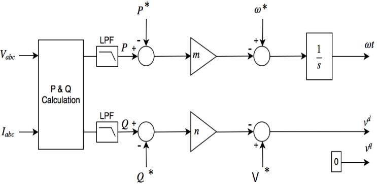
Fig -7:Implementationoftheconventionaldroopcontrol
Fig -8:Thecharacteristicoftheconventionaldroop control
ThissectionillustratedtheperformanceofPVmoduleand performance of perturb and observe algorithm to track maximumpowerpointofPVmoduleundervariousweather conditions. The PV module simulation is implemented in MATLAB Simulink. The parameter of the PV module (330 SunPowermodules). isdisplayedforonemoduleis:
The efficiency of the P.V system in various weather conditions and turbulence is also asa monitoring method used to track the highest energy point. The photovoltaic modulecharacteristicshowsthe(60)kWphotovoltaiccellin theproposedmodelconsistingof(330)solarmodules.The PV module parameters for a single module are shown as follows:
ItisclearfromFig.10thatthenumberofpanelsconnected inseries(5)successivestages
•T=(0-0.5)sec:witharadiationintensityof(200)W/ ataconstanttemperature(25°C),thentheintensityof solarradiationincreasesto1000W/ gradually
•T=(0.5-2)sec:theradiationintensityremainsconstant,

• T=(2-4)sec:the radiation intensitygraduallydecreases untilitreaches(300)W/
• T=(4-5)sec:the radiation intensitygraduallydecreases from300tozero.
•T=(5-6)sec:theradiationintensitybecomes(0),meaning that the two stations exit the system and give electrical energy=0,andtheloadderivesitsenergyfromtheelectrical grid.
2022, IRJET | Impact Factor value: 7.529 | ISO 9001:2008 Certified Journal | Page686
International Research Journal of Engineering and Technology (IRJET) e-ISSN:2395-0056
Volume: 09 Issue: 11 | Nov 2022 www.irjet.net p-ISSN:2395-0072
Fig -01:IrradianceinputtothePVarray
Theactivepoweroutputcurveofthephotovoltaiccellsover timewithavariablesolarirradiancevaluefrom200to1000 W/ asinFigure11andataconstant25°C.Themaximum valueofthecapacityofthesolarcellsis60kW,andwiththe changeofsolarradiationovertime,whenthesystemstarts inthefirst0.5sec,asuddenchangeinthevalueofelectric energy occurred when using the virtual impedance technologytosharetheelectricpoweroftheloadswiththe microgrid.
Fig-01:Activepoweroutputofthetwoinverters (withoutpowersharing)
Case study (2): Simulation results when using the virtual impedance control techniqueto share theactivepower of twoIdenticalinvertersconnectedtothemicro-gridhavethe sameoutputpower.
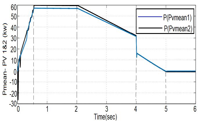
Fig.02 shows the output power of each inverter. It is assumedthatbothinvertersworktogetherinparallelasthe inverteriscontrolledbycontrollingthevoltagesourceusing the visual impedance. Where it was found from the operation that the output capacity of the first inverter (whichoutputisconnectedtoafilteroftypeLCL)doesnot reachitsmaximumpower,butisloweredfromitbyasimple value
Fig -01:ActivepowermeanofthetwoPV
Case study (1): Simulation results if no droop control technique or no virtual impedance is applied to share the outputpoweroftwoidenticalmicro-gridinverters.
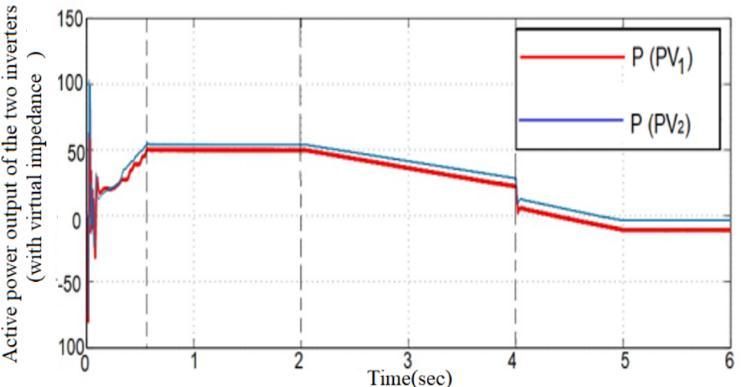
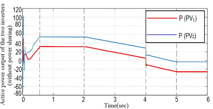
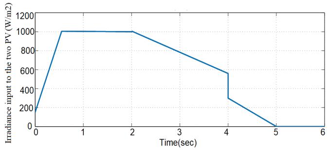
Figure01illustratestheoutputpowerofeachinverter.Itis assumedthatbothinvertersarealreadyoperatinginparallel andthatthewithoutpowersharing.Wenotethattheoutput ofthesecondreflector(Ppv2)givesitsfullvalue,whilethe first (Ppv1) reflector gives a much lower value with the change in solar radiation. the power responses lost the stability
Fig-13:Activepoweroutputofthetwoinverters (withvirtualimpedance)
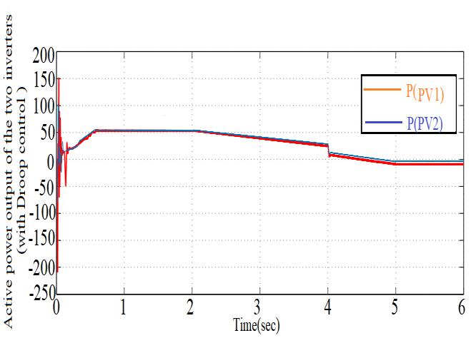
Case study (3): Simulation results when using the droop controltechniquetosharetheoutputpoweroftwoIdentical invertersconnectedtothemicro-grid.
Fig.14 shows the output power of each inverter. It is assumedthatbothinvertersworktogetherinparallelasthe inverteriscontrolledbyvoltagesourcecontrolusingdroop control. The process shows that the output capacitance of thefirstinverter(whichoutputisconnectedtoaLCL-type filter)hasafastresponseandachievescooperationwiththe changeinthevalueoftheoutputpowerofthesolarcells.
International Research Journal of Engineering and Technology (IRJET) e-ISSN:2395-0056
Volume: 09 Issue: 11 | Nov 2022 www.irjet.net p-ISSN:2395-0072
balancedandstableineffectiveforcesharingwhentheline resistanceisactuallychangedfromthedefaultimpedance technology,plusitdoesnotneedhumanintervention.
Table -1: ComparisonbetweenDroopcontrolandVirtual impedance
Comparison scheme
Capabilitytoset powerratio
(v/f)Droop control technique
Fig -14:Activepoweroutputofthetwoinverters (withdroopcontrol)
In this article, two methods of output power sharing betweeninvertersconnectedinparallelwiththemicro-grid, namelydroopcontrolandvirtualimpedance,areproposed tobeappliedtoACnetworkstoensurehighaccuracyand flexibilityinelectricpowersharing.Andweconcludefrom the results obtained from simulations in the Mat-lab / Simulink environment for two parallel inverters can be painted:
•Whenvirtualimpedancecontrolisappliedinasmallgrid systemasatechniqueforsharingelectricalenergybetween inverterswithfuzzyusedtoimprovetheoutputshapeofthe effectivepower,itdoesnotworkwellunderthesechanging conditions,astheeffectivepowersharingisaffectedbythe virtualimpedancesinthesmallgridbetweentheinverters. TransformersandPCCduringthesharingprocess.
• To overcome this problem, the proposed droop control technique is applied to adjust the line resistance value to properly share the effective power between the inverters andworkbetterunderthesameconditionsevenwhenthere aredifferencesinthelineresistanceinasmallnetwork.
•Thevoltagedroopcanbereducedintheproposeddroop controltechnique.
•SwingcontrolTheabilitytoquicklyswitchaccordingtothe proportionsoftheactiveelectricalpoweraccurately.
When implementing a proposed micro-grid with VSI transformersparalleltotheelectricalnetworkforsupplying connectedelectricalloads,considerationshouldbegivento: DC sources with galvanic isolation; Determines the total electrical capacity of the load. In addition, the controller controls each of the VSI switches connected to the micronetwork so that no interference occurs and the system is balanced,stable,andworkswell.
Ithasbeenscientificallyprovenfromthesimulationresults that the proposed droop control method is superior and worksbetterandmoreaccuratelywhilemakingthesystem
Virtual impedance scheme
Yes, without the needforfuzzy Yes,butneedsa fuzzy
- Fast dynamic response at the start of the operation
- Very flexible and has the abilitytoexpand. -Systemstability and power sharingaccuracy -Itisnotaffected by any fundamental change in the system -Ease of implementation intheabsenceof contact between theinverters
-Inaccurate voltage and frequency regulation
-Can be used with linear and non-linearloads when electric powerisshared - Reduces harmonic voltage -Decoupled active and reactive power controls
-Low dynamic response -It is necessary to know the physical variablesfirst -Inaccurate voltage and frequency regulation -Affectedbyany physical change inthesystem
- The system is unstable, especially when starting, and less accurate in sharing electric power
International Research Journal of Engineering and Technology (IRJET) e-ISSN:2395-0056
[1] W. R. Issa, A. H. E. Khateb, M. A. Abusara, and T. K. Mallick,“Controlstrategyforuninterruptedmicrogrid modetransferduringunintentionalislandingscenarios,” IEEETransactionsonIndustrialElectronics,vol.65,no. 6,pp.4831–4839,2018.Viewat:PublisherSite|Google Scholar
[2] P. Sreekumar and V. Khadkikar, “Adaptive power management strategy for effective volt-ampere utilization of a photovoltaic generation unit in standalonemicrogrids,”IEEETransactionsonIndustry Applications,vol.54,no.2,pp.1784–1792,2018.View at:PublisherSite|GoogleScholar
[3] W.R.Issa,M.A.Abusara,andS.M.Sharkh,“Controlof transient power during unintentional islanding of microgrids,” IEEE Transactions on Power Electronics, vol.30,no.8,pp.4573–4584,2015.Viewat:Publisher Site|GoogleScholar
[4] Transactions on Power Electronics, vol. 30, no. 8, pp. 4573–4584, 2015.View at: Publisher Site | Google Scholar
[5] M.Hossain,H.Pota,W.Issa,andM.Hossain,“Overview of AC microgrid controls with inverter-interfaced generations,”Energies,vol.01,no.9,p.0211,1107.View at:PublisherSite|GoogleScholar
[6] W.Issa,S.Sharkh,T.Mallick,andM.Abusara,“Improved reactivepowersharingforparallel-operatedinvertersin islandedmicrogrids,”JournalofPowerElectronics,vol. 16,no.3,pp.1152–1162,2016.Viewat:PublisherSite| GoogleScholar
[7] J. M. Guerrero, L. GarciadeVicuna, J. Matas, M. Castilla, andJ.Miret,“Awirelesscontrollertoenhancedynamic performance of parallel inverters in distributed generation systems,” IEEE Transactions on Power Electronics,vol.19,no.5,pp.1205–1213,2004.Viewat: PublisherSite|GoogleScholar
[8] W.R.Issa,M.A.Abusara,andS.M.Sharkh,"Impedance interaction between islanded parallel voltage source inverters and the distribution network," in IET ConferencePublications,2014,vol.2014,no.
[9] S.-J.Ahn,J.-W.Park,I.-Y.Chung,S.-I.Moon,S.-H.Kang, and S.-R. Nam, “Power-sharing method of multiple distributedgeneratorsconsideringcontrolmodesand configurations of a microgrid,” IEEE Transactions on Power Delivery, vol. 25, no. 3, pp. 2007–2016, 2016.Viewat:PublisherSite|GoogleScholar
[10] Y. W. Li and C. N. Kao, “An accurate power control strategy for power-electronics-interfaced distributed
Volume: 09 Issue: 11 | Nov 2022 www.irjet.net p-ISSN:2395-0072 © 2022, IRJET | Impact Factor value: 7.529 | ISO 9001:2008 Certified Journal | Page689
generation units operating in a low-voltage multibus microgrid,”IEEETransactionsonPowerElectronics,vol. 24,no.12,pp.2977–2988,2009.Viewat:PublisherSite| GoogleScholar
[11] M. Wegmuller, J. P. von der Weid, P. Oberson, and N. Gisin,"Highresolutionfiberdistributedmeasurements with coherent OFDR," in Proc. ECOC'00, 2000, paper 11.3.4,p.109.
[12] Y. Mohamed and E. F. El-Saadany, “Adaptive decentralized droop controller to preserve power sharing stability of paralleled inverters in distributed generation microgrids,” IEEE Transactions on Power Electronics, vol. 23, pp. 2806–2816, 2008.View at: GoogleScholar
[13] M. N. Marwali, J.-W. Jung, and A. Keyhani, “Control of distributed generation systems-part II: load sharing control,”IEEETransactionsonPowerElectronics,vol. 19,no.6,pp.1551–1561,2004.Viewat:PublisherSite| GoogleScholar
[14] I.-Y. Chung, W. Liu, D. A. Cartes, E. G. Collins, and S.-I. Moon, “Control methods of inverter-interfaced distributed generators in a microgrid system,” IEEE TransactionsonIndustryApplications,vol.46,no.3,pp. 1078–1088, 2010.View at: Publisher Site | Google Scholar
[15] S.T.Cady,A.D.Dominguez-Garcia,andC.N.Hadjicostis, “A distributed generation control architecture for islandedacmicrogrids,”IEEETransactionsonControl Systems Technology, vol. 23, no. 5, pp. 1717–1735, 2015.Viewat:PublisherSite|GoogleScholar
[16] Y. Zhang and H. Ma, “Theoretical and experimental investigationofnetworkedcontrolforparalleloperation of inverters,” IEEE Transactions on Industrial Electronics,vol.59,no.4,pp.1961–1970,2012.Viewat: PublisherSite|GoogleScholar
[17] R.Majumder,G.Ledwich,A.Ghosh,S.Chakrabarti,andF. Zare, “Droop control of converter-interfaced microsources in rural distributed generation,” IEEE TransactionsonPowerDelivery,vol.25,pp.2768–2778, 2010.Viewat:GoogleScholar
[18] Ch, Sai Babu & Kumari, J. & Kullayappa, T. (2011). “Design and Analysis of Open Circuit Voltage Based Maximum Power Point Tracking for Photovoltaic System”. International Journal of Advances in Science andTechnology.2.51-60.tronics,55,2610-2621.
[19] R. Issa, T. K. Mallick, and M. Abusara, “Supervisory control for power management of an islanded AC microgridusingafrequencysignalling-basedfuzzylogic controller,” IEEE Transactions on Sustainable Energy,
International Research Journal of Engineering and Technology (IRJET) e-ISSN:2395-0056
vol.10,no.1,pp.94–104,2019.Viewat:PublisherSite| GoogleScholar
[20] T.F.Wu,Y.K.Chen,Y.H.Huang,W.Tsai-Fu,C.Yu-Kai, andH.Yong-Heh,“2Cstrategyforinvertersinparallel operationachievinganequalcurrentdistribution,”IEEE TransactionsonIndustrialElectronics,vol.47,no.2,pp. 273–281,2000.Viewat:PublisherSite|GoogleScholar
[21] Y.Pei,G.Jiang,X.Yang,andZ.Wang,“Auto-master-slave controltechniqueofparallelinvertersindistributedAC power systems and UPS,” in Proceedings of the 2004 IEEE 35th Annual Power Electronics Specialists Conference (IEEE Cat. No.04CH37551), Aachen, Germany, June 2004.View at: Publisher Site | Google Scholar
[22] A. M. Roslan, K. H. Ahmed, S. J. Finney, and B. W. Williams, “Improved instantaneous average currentsharingcontrolschemeforparallel-connectedinverter considering line impedance impact in microgrid networks,”IEEETransactionsonPowerElectronics,vol. 26,pp.702–716,2011.Viewat:GoogleScholar
[23] Y.Xing,L.Huang,S.Sun,andY.Yan,“Novelcontrolfor redundant parallel UPSs with instantaneous current sharing,” in Proceedings of the Power Conversion Conference-Osaka 2002 (Cat. No.02TH8579), Osaka, Japan, April 2002.View at: Publisher Site | Google Scholar
[24] ]Femia,N.,Lisi,G.,Petrone,G.,Spagnuolo,G.andVitelli, M.(2008)DistributedMaximumPowerPointTracking of Photovoltaic Arrays: Novel Approach and System Analysis.IEEETransactionsonIndustrialElec
[25] S.-H. Hu, C.-Y. Kuo, and T.-L. Lee, “Design of virtual inductancefordroop-controlledinverterwithseamless transition between islanded and grid-connected operations,”1101IEEEEnergyConversionCongressand Exposition(ECCE),vol.2012,pp.4383–4387,2012.View at:PublisherSite|GoogleScholar
[26] J.Padhye,V.Firoiu,andD.Towsley,"Astochasticmodel ofTCPRenocongestionavoidanceandcontrol,"Univ.of Massachusetts,Amherst,MA,CMPSCITech.Rep.99-02, 1999
[27] Omid Abdoli , Mehdi Gholipour Rahmat-allah , Hooshmand“Improvingsynchronizationstabilityofgrid connectedconvertersbyvirtualimpedance”IETGener. Transm.Distrib.2021;15:1136–1143
[28] T. Esram, P.L. Chapman, "Comparison of Photovoltaic Array Maximum Power Point Tracking Techniques," IEEETransactionsonEnergyConversion,vol.22,no.2, pp.439-449,June2007.
Volume: 09 Issue: 11 | Nov 2022 www.irjet.net p-ISSN:2395-0072 © 2022, IRJET | Impact Factor value: 7.529 | ISO 9001:2008 Certified Journal | Page690
[29] ] AparnaKP,PriyaR,andS.Suryanarayanan,"Modeling andsimulationofaPVsystemusingDC-DCconverter," InternationalJournalofLatestResearchinEngineering and Technology (IJLRET), PP.09-16, vol. 1, no. 2, July, 2015
[30] W.Issa,M.Abusara,S.Sharkh,andT.Mallick,“Asmall signalmodelofaninverter-basedmicrogridincluding DC link voltages,” in Proceedings of the 2015 17th European Conference on Power Electronics and Applications (EPE’04 ECCE-Europe), Geneva, Switzerland,September2015.Viewat:PublisherSite| GoogleScholar
[31] W.Issa,A.ElKhateb,N.Anani,andM.Abusara,“Smooth mode transfer in AC microgrids during unintentional islanding,” Energy Procedia, vol. 023, pp. 01–20, 2017.Viewat:PublisherSite|GoogleScholar
[32] Abdelwahab, Saad & Hamada, Abdallah & Abdellatif, Walid. (1111), “Comparative Analysis of the Modified Perturb&ObservewithDifferentMPPTTechniquesfor PV Grid Connected Systems”, International Journal of RenewableEnergyResearch.10.155-164.
[33] 32.M. Abusara, J. M. Guerrero, and S. Sharkh, "Line InteractiveUPSforMicrogrids," IEEETransactionson IndustrialElectronics,pp.1-8,Mar2014.
[34] H.Tao,J.L.Duarte,andM.A.Hendrix,"Line-interactive UPS using a fuel cell as the primary source," IEEE TransactionsonIndustrialElectronics,vol.55,pp.30123021,Jul2008.
[35] K. Ashok Reddy, Kota Srinivas and G.S. Ayyappan" Power Management in a Standalone Solar/ Fuel cell/ Batteryhybridpowersystems"InternationalJournalof Engineering Research and Development, Volume 9, Issue6December2013.
[36] ErkanDursun,OsmanKilie"Comparativeevaluationof differentpowermanagementstrategiesofastand-alone PV/Wind/PEMFChybridpowersystem "international journalofElectricalpowerandenergysystems.Volume 34,Januar