International Research Journal of Engineering and Technology (IRJET) e-ISSN: 2395-0056

Volume: 09 Issue: 11 | Nov 2022 www.irjet.net p-ISSN: 2395-0072
Comparative computational performance Analysis of shell and tube heat exchanger with and without SiO2 nanofluid
Abhimanyu Kumar1 , Animesh singhai2
1Research Scholar, Department of Mechanical Engineering Trinity Institute of Technology and Research Bhopal, India
2Asst. Professor, Department of Mechanical Engineering Trinity Institute of Technology and Research Bhopal, India ***
Abstract Considerable amount of work has been done to deal the exergy balance aspects in thermal engineering field. The present study aims the computational comparative analysis of performance parameters of a concentric shell and tube heat exchanger with and without nanoparticles under different mass flow rates of cold fluid. The results reported significant improvement in maximum heat transfer rate, overall heat transfer coefficient, LMTD and effectiveness with the use of Nanoparticles in lined with previous studies.
Keywords heat exchanger, CFD analysis, nanofluid,SiO2,solidworks
1. INTRODUCTION
Heat Exchanger is a device used for energy transfer betweenfluidsforindustrialpurposes Heatexchangerisa broadly used term for a category of devices. The devices such as evaporators, recuperators, condensers, and any more fall under the category of heat exchanger. Heat exchangersareclassifiedbasedonvariousaspects,suchas: [1]
1.4 Heat Transfer Enhancement
Avarietyoftechniquesareusedinordertoimprovethe performance of heat exchanger. The performance of heat exchangerismeasuredbytheamountofheatexchangedin a given time between the two streams of fluids. The techniques are classified in broad 2 categories. They are termed as Active heat transfer enhancement techniques, and passive heat transfer enhancement techniques. In active heat transfer enhancement techniques, additional power is supplied to get the desired increase in heat transfer rate, whereas in passive heat transfer techniques, heat transfer enhancement is achieved by changing the shape of the pipes or by changing the quality of working fluidsormaterialsused.[2]
1.5 NANOFLUIDS:
A nanofluidisa mixtureofa baseliquid with nano size particles of either metal oxides, or carbides, which improves the four necessary properties of the base fluid which are density, viscosity, thermal conductivity, and specific heat. These improvement in properties allow fluid to transfer more heat in comparison to the base fluid. The nano particle used for our research purpose is silicon dioxide (SiO2), whose properties are calculated and representedinTable1.[3]
2. INTRODUCTION TO SOLIDWORKS
Solidworks is a software used for virtual modelling and analysis of systems used for engineering designs. It is a product of Dassault systems. The software tool basically used for virtual modelling for representation of design. Analysis can be done in software for finding out optimum values.
2.1 STEPS FOR SOLVING A GENERAL PROBLEM IN SOLIDWORKS:
Similar to solving any problem analytically, you need to define
(1)problemdomain, (2)Virtualmodel,
© 2022, IRJET | Impact Factor value: 7.529 | ISO 9001:2008 Certified Journal | Page632
International Research Journal of Engineering and Technology (IRJET) e-ISSN: 2395-0056
Volume: 09 Issue: 11 | Nov 2022 www.irjet.net p-ISSN: 2395-0072
(3)Boundaryconditionsand
(4) Physicalproperties.
You then solve the matter and present the results. In numerical ways, the most distinction is an additional step referred to as mesh generation. This can be the step that divides the advanced model into little components that become resolvable in Associate in Nursing otherwise too advancedscenario.Belowdescribestheprocessesin word slightlyadditionaladjusttothesoftwaresystem [4]
2.1.1 Virtual Modelling
Constructatwoorthreedimensionalvirtualmodelofyour projectfortherepresentationoftheobjectandtestitusing the work plane coordinates system within Flow simulation-SOLIDWORKS.
2.1.2 Assigning material
Now that the part is modelled, outline a library of the mandatory materials that compose the item (or project) being modelled. This includes thermal and mechanical properties
2.1.3 Generate Mesh
AtthispointSOLIDWORKSunderstandsthemakeupofthe part. Now define how the Modelled system should be broken down into finite pieces in order to perform the calculation of a infinitesimal object and then the system willusetheiterativemethodtointegratetheresultsforthe completesystem.
2.1.4
Problem set-up
Oncethesystemisfullydesigned,thelasttask istoset-up the system with constraints, such as physical loadings or boundaryconditions.Here wewill beprovidingflowrates offluid,gravityeffectandtypeofdifferentialequationthat theproblemisdependingupon.
2 1.5 Generate Solution
Here the software requires information about the type of analysis that it has to undertake (steady state/transient). Thesoftwarealsorunsasampleof10iterationsinorderto check that whether the solution will converge to a unique valueornot.
2.1.6 View Results/Reports (post Processing)
Post Processing is the technique of getting the solution represented in the format you desire. SOLIDWORKS provides various ways in which the solution can be presented in, and you can choose from among them such astables,graphs,andcontourplots.[5]
3. METHODOLOGY
3.1 CFD PROCESS ANALYSIS:
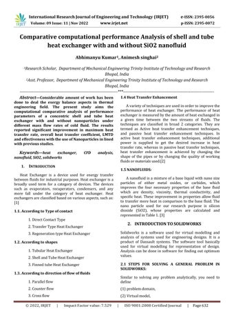
The results are simulated with the help of SOLIDWORKS 22 software and a Computational Fluid Dynamics (CFD) analysis is performed in order to get the validation of the results. The simulation is carried out as describedbyablockdiagramshowninfig1[6]
Fig1CFDProcess[7]
3.2 COMPUTATIONAL PROCEDURE:
1. A concentric shell and Tube heat exchanger is virtually designed in SolidWorks software, 2022 version. The dimensions of the heat exchanger are as per the experimentalbasepaper.
2.Theinnertubehasaninnerdiameterof12mmandouter diameter of 14mm, whereas the shell is made of inner diameter of 17mm and outer diameter of 18mm respectively.
3.Thematerialusedforboththetubesarecopperwithits standard properties at given temperature. The inlet temperature of cold fluid is kept at 303K and inlet temperature of hot fluid is kept at 343K. The mass flow rate of hot fluid flowing through the annuus of both the tubes is kept constant at a value of 0.05kg/s, whereas the massflowrateofcoldfluidflowingthroughtheannulusis varied from 0.05kg/s, 0.1kg/s, 0.15kg/s, and 0.2kg/s respectively.
4. The initial readings of this virtual model is validated with experimental results of our base paper. The waterwater heat exchanger results are calculated, and data is presented for heat transfer rate, effectiveness, and LMTD values.
International Research Journal of Engineering and Technology (IRJET) e-ISSN: 2395-0056
Volume: 09 Issue: 11 | Nov 2022 www.irjet.net p-ISSN: 2395-0072
5. A Nano-Fluid is defined in virtual software whose properties are calculated based on standard formulas as mentionedahead.Thecoldwaterflowingthroughannulus is replaced by this nano fluid while keeping the inlet temperatureanditsmassflowratesame.Thecalculations arefoundforthisarrangementaswell.Also,thenanofluid is checked for various values of volume fraction, and the bestsuitablevolumefractionisusedforthecalculations.
6. The results are compared on the basis of heat transfer rate, LMTD, overall heat transfer coefficient and effectivenessofheatexchanger.
4. MATHEMATICAL AND ANALYTICAL PROCEEDURE
4.1CalculationofPropertiesofnanofluid
As discussed above, the nanofluid is considered on 4 differentpropertiesoffluid.Theyarecalculatedasfollows: [8]
4.1.1. Volume Fraction:
ANano-Fluidismadeupofasolutionofadissolvingliquid, and nano particles of any suitable metal, oxides or carbides. The concentration of these particles in this base fluidisofimportance becauseit changesthepropertiesof nanofluid.
Cp(nf):Specificheatofnanofluid Cp(s):Specificheatofsolid Cp(w):Specificheatofwater
4.1.3 Viscosity of nano fluid:
Thisistheresistancetoflowthatiscausedbyshearstress inthenanofluid.
where, µ(nf):DynamicviscosityofnanoFluid.
4.1.4 Thermal conductivity of Nano Fluid:
4.1.5 Performacne parameters of Heat exchanger
A. Heat Transfer Rate: Heat Transfer Rate of Hot Fluid:
As the inlet and outlet temperature of both the fluids are knownthen,wecanfindouttherateofheattransferofhot fluidbythefollowingexpression.
Q=mcCp(Tco–Tci)
B. Heat Transfer Rate of Cold Fluid:
4.1.1. Density of Nano Fluid:
Duetotheadditionof two different densitiesofmaterials, the resultant density of solution changes and it can be calculatedasshown. Where, ρnf:Densityofnanofluid.
Φ:VolumeFraction
ρw:Densityofwater
ρs:Densityofsolid
4.1.2. Specific heat of nano fluid:
This is the net heat that one kg of nano fluid will be requiringinordertoraiseitstemperatureto1K.
With the help of the temperatures of cold fluid inlet and outlet we can find out the heat gained by cold fluid by the followingexpression.
Q=mhCp(Thi–Tho)
The heat gained by cold fluid must be exactly equal to the heat lost by the hot fluid in fully adiabatic boundary condition. But since the surface cannot be fully adiabatic thus,weconsiderrateofheatlossbyhotfluidastheactual heattransferrateofthesystem.
C. Logarithmic Mean Temperature Difference:
At different section along the length of circular tubes the temperature difference between hot fluid and cold fluid willbedifferent,asthehotfluidwillcontinuouslybelosing heat to cold fluid. Logarithmic mean temperature difference is the equivalent temperature difference which can be used to calculate heat transfer rate of the heat exchangerifitissubstitutedinthegeneralequationofheat transfer in Heat exchanger. We find out the logarithmic mean temperature difference for every case by using the followingexpression.
Where,
Where,
International Research Journal of Engineering and Technology (IRJET) e-ISSN: 2395-0056
Volume: 09 Issue: 11 | Nov 2022 www.irjet.net p-ISSN: 2395-0072
5. Results
5.1 Properties of SiO2 Nano Fluid as calculated based on above formula
Table 1: Properties of Nano Fluid
=T1 (Hotfluidinlettemperature)–T4 (Coldfluidexit temperature)
=T2 (Hotfluidexittemperature)–T3 (Coldfluidinlet temperature)
=Logarithmicmeantemperaturedifference.
D. Overall Heat Transfer Coefficient:
The overall heat transfer coefficient is a measure of the overall ability of a series of conductive and convective barriers to transfer heat. It is commonly applied to the calculation of heat transfer in heat exchangers, but can be appliedequallywelltootherproblems.
Forourcaseofheatexchanger,sincewealreadyknowthe value of heat transfer rate thus we can use the following equation to determine the value of Overall Heat Transfer Coefficient.
S.No mfC (kg/s) Volume Fraction mf(Nanoparti cleinkg/S)
NanoFluidPropertyTable
Densityof SiO2Nano Fluid SpecificHeatof NanoFluid(J/kg-K) ViscosityofNanoFluid Knf(W/mK)
1 0.05 0.4 0.08860 1658.2 1977.121819 0.002 1.259864
2 0.05 0.3 0.05696 1492.9 2346.076294 0.00175 1.034068
3 0.1 0.4 0.17720 1658.2 1977.121819 0.002 1.259864
4 0.1 0.3 0.11391 1492.9 2346.076294 0.00175 1.034068
5 0.15 0.4 0.26580 1658.2 1977.121819 0.002 1.259864
6 0.15 0.3 0.17087 1492.9 2346.076294 0.00175 1.034068
7 0.2 0.4 0.35440 1658.2 1977.121819 0.002 1.259864
8 0.2 0.3 0.22783 1492.9 2346.076294 0.00175 1.034068
U=Overallheattransfercoefficient(Watts/m2K).
E. Effectiveness of Heat Exchanger:
Itisadimensionlessparameteranddefinedastheratioof actual heat transfer rate ' by heat exchanger to maximumpossibleheattransferrate 'itisdenoted by'ε'.
Thevalueofeffectivenessoftheheatexchangercanalsobe determined for each case by using the following expression.[9][10][11][12]
The properties of nano fluid which are required to be inserted in solidworks software are calculated. The four necessary properties are Density of nano fluid, specific heat of nano fluid, Viscosity of nano fluid and thermal conductivity of nano fluid. The above tabulated calculations are made for volume fraction 0.4 and 0.3 respectivelyforalltheflowratesof0.05,0.1,0.15,0.2kg/s respectively.
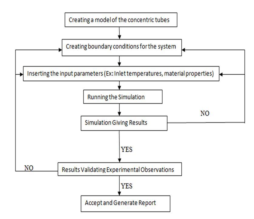
5.2 Generated Report:
Fig2FrontViewofModeloftheShellandTubeHeat Exchanger
International Research Journal of Engineering and Technology (IRJET) e-ISSN: 2395-0056
Volume: 09 Issue: 11 | Nov 2022 www.irjet.net p-ISSN: 2395-0072
Fig3SideViewofShellandTubemodel
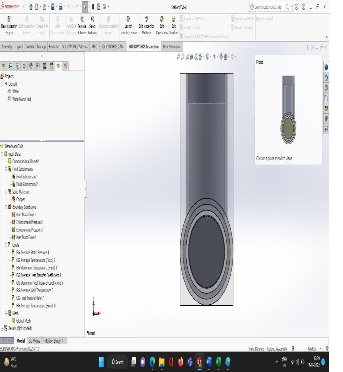
Fig6OutletTemperature(incaseofwater-Nano-Fluid heatexchanger)asdisplayedbysoftware
Fig4OutletTemperature(incaseofwater-waterheat exchanger)asdisplayedbysoftware
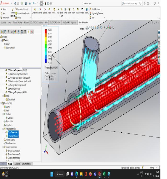
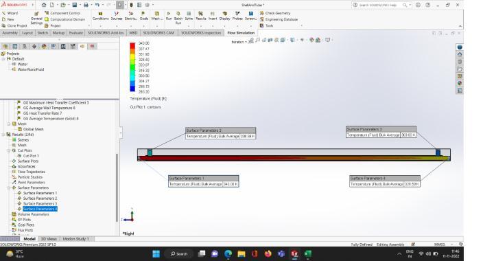
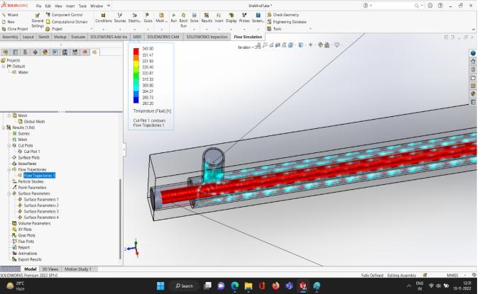
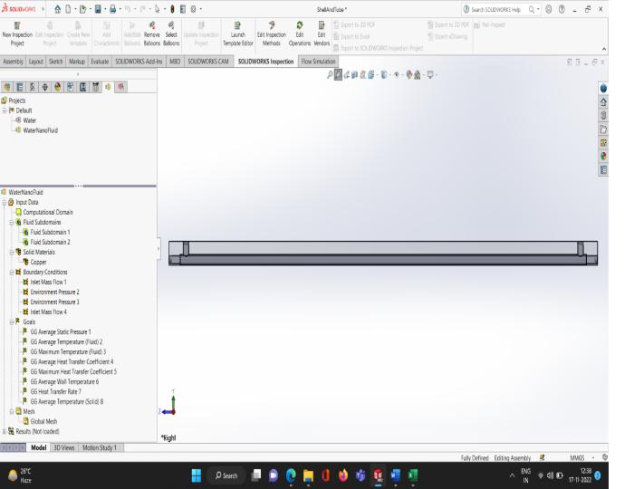
Fig7FlowTrajectories(Water-Nano-Fluid)flowinginside thetubeonaClipplane
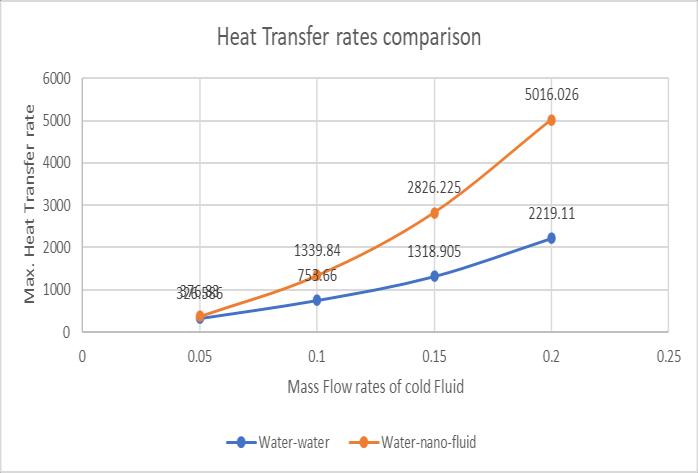
5.3 Comparison of Heat Transfer Rate of water heat exchanger with nano-fluid heat exchanger.
Fig 8 shows the comparative values of heat transfer rates ofconcentriccircularplanetubeswithoutanyinserts,with water flowing as hot fluid in both the cases but in case of coldfluid,onearrangementhaswaterflowingascoldfluid andthenexttime,theSiO2nanofluidwithvolumefraction of 0.4 is flowing as cold liquid respectively. The comparison shows that the maximum value of heat transferrateforthesameflowratesisachievedforwaternanofluidarrangementat0.2kg/swithavalueof5016.026 watts.
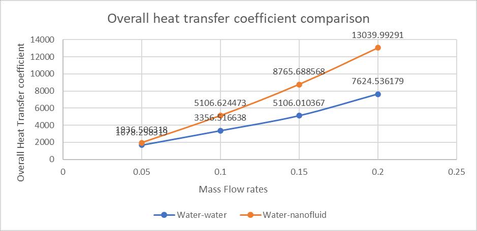
5.4 Comparison of Overall Heat Transfer coefficient based on Computational analysis
Fig5FlowTrajectoriesofTemperatureofHotFluid flowinginsidethetubeonaClipplane
Fig 9 shows the comparative values of Overall Heat transfer coefficient of concentric circular plane tubes without any inserts, with water-water arrangement and
International Research Journal of Engineering and Technology (IRJET) e-ISSN: 2395-0056
Volume: 09 Issue: 11 | Nov 2022 www.irjet.net p-ISSN: 2395-0072
water-nanofluid arrangement respectively. The comparisonshowsthatthemaximumvalueofOverallHeat transfer coefficient for the same flow rates is achieved water-nanofluid arrangement at 0.2kg/s with a value of 13039.99291(Watts/(m2-K))
5.6 Comparison of Effectiveness based on Computational analysis of all the three cases
Fig 11 shows the comparative values of effectiveness of concentric circular plane tubes without any inserts, with counter flow arrangement in water-water and waternanofluidsystemrespectively.Thecomparisonshowsthat themaximumvalueofeffectivenessforthesameflowrates isachievedforwater-nanofluid
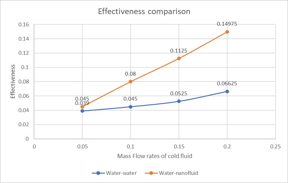
Fig8RateofHeatTransferversusmassflowrateofHot FluidinCounterFlowarrangement
Fig10LMTDversusmassflowrateofcoldFluidinCounter Flowarrangement
Fig9OverallHeattransfercoefficientversusmassflow rateofColdFluidinCounterFlowarrangement
5.5 Comparison of LMTD based on Computational analysis of all the cases
Fig 10 shows the comparative values of LMTD of concentric circular plane tubes without any inserts, with water-water and water-nanofluid arrangement respectively. The comparison shows that the maximum value of LMTD for the same flow rates is achieved for water-nanofluid arrangement, and it was at its maximum on0.2kg/swithavalueof 9.21088.
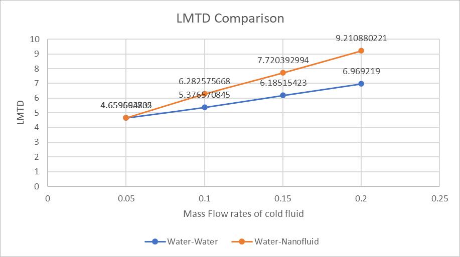
Fig11EffectivenessversusmassflowrateofHotFluidin CounterFlowarrangement
6. CONCLUSION:
1) In this research work the properties of SiO2 nanofluid werefound outanddefined insoftwareforvarious values of concentration factor. The performance of nanofluid is observed to be optimum at concentration factor of 0.4, which was selected to calculate the performance of heat exchanger.
International Research Journal of Engineering and Technology (IRJET) e-ISSN: 2395-0056
Volume: 09 Issue: 11 | Nov 2022 www.irjet.net p-ISSN: 2395-0072
2) In the present research work it is found out that the overallheattransfercoefficientishavingamaximumvalue of7624.53Watts/m2kforthecounterflowarrangementof water-water type heat exchanger which is 42% less than the value we obtained for water-nanofluid arrangement, whichhasavalueof13039.99Watts/m2K.
3) It is noted that LMTD for water-nanofluid arrangement was found to be 9.21 K which is greater than water-water arrangementby24%.
4) The effectiveness of water-nanofluid arrangement was also found to be maximum with a value of 0.149 which is more than that of water-water heat exchanger arrangement by 56% at a volume flow rate of 0.2kg/s of coldwater.
5) The maximum heat transfer rate was noted to be increased by an amazing amount of 55% for a mass flow rate of 0.2kg/s water-nanofluid arrangement in comparison to the water-water arrangement which had a valueof2219.11Wattsforthesameworkingconditions.
REFERENCES
[1] Chaiyanan Kamsuwan, Xiaolin Wang, Lee Poh Seng , Cheng Kai Xianc , Ratchanon Piemjaiswang, Pornpote Piumsomboona, Yotsakorn Pratumwal, Somboon Otarawanna, Benjapon Chalermsinsuwan (2022). Simulation of nanofluidmicro-channel heat exchanger using computational fluid dynamics integrated with artificialneuralnetwork,9thInternationalConference on Power and Energy Systems Engineering (CPESE 2022),DoshishaUniversity,Kyoto,Japan,(2022).
[2] Vedant Irabatti, Yash Patil, Sandeep Kore, Vaishnavi Barangule, Abhishek Kothe (2022). Comprehensive review of spiral heat exchanger for diverse applications.MaterialsToday:Proceedings(2022).
[3] S. Raja, MS. Sivahari Shankar, P. Mathan Kumar , C. Rajaganapathy (2022). Heat transfer analysis and enhancement in shell and tube heat exchanger using copper oxide Nano particles; Materials Today: Proceedings(2022).
[4] Pavushetti Abhilash, Udutha Raghupati, Raghavan Nanda Kumar(2021).DesignandCFDanalysisofhair pin heat exchanger using aluminium and titanium carbide nanofluids; Materials Today: Proceedings (2021).
[5] N. Parthiban, M. Rajkumar, S.N. Murugesan (2021). Experimental study of comparison in performance of heat exchanger with and without silicon dioxide nano particle used in cold fluid. Materials Today: Proceedings(2021).
[6] Shu-Rong Yana, Hazim Moria , Samira Pourhedayat , Mehran Hashemian (2020). A critique of effectiveness concept for heat exchangers; theoretical-experimental study,InternationalJournalofHeatandMassTransfer (2020).
[7] J.I. Corcoles , J.D. Moya-Rico, A.E. Molina, J.A. Almendros-Ib anez (2020). Numerical and experimental study of the heat transfer process in a double pipe heat exchanger with inner corrugated tubes. International Journal of Thermal Science (2020).
[8] Miftah Altwieb, Krzysztof J. Kubiak, Aliyu M. Aliyu, Rakesh Mishra (2020). A new three-dimensional CFD model for efficiency optimisation of fluid-to-air multifin heat exchanger. Thermal Science and Engineering Progress(2020).
[9] A. Zargoushi, F. Talebi, S.H. Hosseini (2019). CFD modeling of industrial cold box with plate-fin heat exchanger: Focusing on phase change phenomenon. International Journal of Heat and Mass Transfer (2019).
[10] Chamil Abeykoon (2019). Compact heat exchangers –Design and optimization with CFD International JournalofHeatandMassTransfer146(2020)118766
[11] P.C. Mukesh Kumar, M. Chandrasekar (2019). CFD analysis on heat and flow characteristics of double helically coiled tube heat exchanger handling MWCNT/waternanofluids Heliyon5(2019)e02030
[12] A.Natarajan,R.Venkatesh,S.Gobinath,L.Devakumar, K. Gopalakrishnan (2019) CFD simulation of heat transfer enhancement in circular tube with twisted tape insert by using nanofluids. Materials Today: Proceedings(2019).