International Research Journal of Engineering and Technology (IRJET) e-ISSN:2395-0056

Volume: 09 Issue: 11 | Nov 2022 www.irjet.net p-ISSN:2395-0072
International Research Journal of Engineering and Technology (IRJET) e-ISSN:2395-0056
Volume: 09 Issue: 11 | Nov 2022 www.irjet.net p-ISSN:2395-0072
1Raghappa M Goykar, 2Dr.P.A. Dode, 3Dr.S.A. Rasal
1Post Graduate Student, Datta Meghe College of Engineering, Navi Mumbai, Maharashtra, India
2Professor and Head, Department of Civil Engineering, Datta Meghe College of Engineering, Navi Mumbai, Maharashtra, India
3Professor, Department of Civil Engineering, Datta Meghe College of Engineering, Navi Mumbai, Maharashtra, India
Abstract - Continuouslyweldedrail(CWR)withthetrackdirectlyfixedonconcretedeckisusedformostelevatedmetro bridge structures. The interaction between the CWR and elevated metro structure due to temperature variation, train loadings like braking/traction and vertical loading takes place through directly fixed rail fasteners, which have a nonlinearforce-displacementrelationship.AccordingtoUIC774-3Rparametersthatinfluencethisinteractionincludes:Type ofsuperstructure,Spanlength,Expansionlength,BendingStiffnessoftheDeckandSupportStiffness.Thispaperpresents rail structureinteraction analysis ofsteel composite metro bridge and case study of an under-construction metro bridge projectD.N.Nagar–Mandale,Mumbai.Thetotallengthconsideredforthepresent studyis743.43moutofwhich260.43 m is steel composite bridge portion and remaining portion are of U-Girder and PSC girder superstructure span as a boundary condition. A three dimensional (3D) finite element analysis was carried out using the software SOFiSTiK. For presentcasestudyresultsarerepresentedintheformofaxialrailstressesalongthelengthofthebridgeandcheckedwith UIC774-3Rpermissiblelimits.
Key words: Railstructureinteraction;Continuousweldedrail;Metrobridge;UIC774-3R
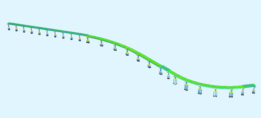
Acontinuouslyweldedrail(CWR)trackhasbeenextensivelyusedmanyadvantages.Comparedwithajointedrailtrack, CWRreducesthemaintenancecostofthetrack,increasetheridingqualityandincreasestheserviceoftrackcomponents. ThemaincomponentsofCWRtrackbridgeiselasticCWR,elasticrailfastenerswhichattachtherailstotheconcreteplinth on the deck of the bridge, superstructure, elastic bearings which supporting the superstructure on the substructure and substructure including foundations. Relative displacement of the rails and structure of the bridge caused by the temperature variation, braking and vertical loading of train. Due to this track bridge interaction phenomenon results in additionalstressestobegeneratedinstructureandthereforeinrails. Mainlyinteractionbetweenrailsandstructuretake placethroughtherailfasteners,whichhaveatakingnonlinearstiffnesslawunderconsideration
CWR directly connected to deck of the bridge by fasteners, since rails is not able to expand or contract when temperature variation occurred in bridge. Temperature increases above the rail installation temperature causes compressive forces in rails that would buckle the rail and temperature decrease below the rail installation temperature causes tensile forces in the rails that would be break the rail. Also, due to rail and structure interaction phenomenon, transverse and longitudinal shear force has been developed at bearing level that should be considered for design of foundation and substructure. This paper focus has mainly on the rail structure interaction analysis of steel composite bridge, for which analysis have been carried by SOFiSTiK software considering the nonlinear spring for rail and deck connectionandshearforceonpierwhichneedtobeconsiderforsubstructureandfoundationdesign
TheinvestigationsonCWRforcesandtheirinfluenceonthedesignofstructureshavebeenindiscussionforthelast30 yearsatnationalandinternationallevels.
Longitudinal forces in continuously welded rails on bridge decks due to nonlinear track bridge interaction (2006) illustrates the longitudinal stresses generated in continuously welded rails on the railway bridge. Longitudinal loads are caused because of braking action of railway, the uniform temperature change of bridge as well as a sudden change of ballaststiffnessatamomentwhentrainreachesthebridge. Basedonstudyresultsitwasfoundthatlongitudinalstresses
© 2022, IRJET | Impact Factor value: 7.529 | ISO 9001:2008 Certified Journal | Page580
International Research Journal of Engineering and Technology (IRJET) e-ISSN:2395-0056
Volume: 09 Issue: 11 | Nov 2022 www.irjet.net p-ISSN:2395-0072
obtained by conventional separate treatment of loading case are higher compared to stresses calculated using proposed correct combination of loading cases. Based on results it was concluded that in certain situations expansion devices are not required. Maximum compressive rail stresses were considerably reduced because of proposed truly nonlinear simulation
Longitudinaltrackbridgeinteractionforloadsequence2008)illustratesthatresultsobtainedfromstaticalapproachare sufficiently accurate and change of coupling stiffness results in increase of largest compression force by 10% is realistic. Author also found that multiple unloading-loading-unloading track after seasonal temperature there is increase linear elasticpartalongtrackbridgecouplinginterface.
Nonlinear rail structure interaction analysis of an elevated skewed steel guideway (2011). This paper focused on determination of rail break gap value and quantifying rail axial stresses and bearing forces and their distribution along lengthofbridge.Basedonresultitwasfoundthatbearingtransferrednegligibleamountoflateralforcestosubstructure. Basedonstudyitwasfoundthat3-DmodellinggivebroadinsightintoRSIforces.Authorconcludesbrokenrailgapmust belessthanstipulatedindesigncriteria.
Thisstudyfocusesonfollowingobjectives,
i)TocarryouttheRSIanalysisofunderconstructionsteelcompositebridgeforMumbaimetroline2B.
ii)Tofindouttheadditionalstressesinrailandlongitudinalforceatbearinglevel.
iii)TochecktheadditionalrailstressesisunderpermissiblelimitgivenbyUIC774-3R.
TheMumbaiMetroLine-2BBridgefromD.N.NagartoMandalehasbeenusedasabasisforthisstudy.Theconfigurationof thebridgeisatwo-track,multi-spansimplysupportedwithsteelcompositegirdersuperstructure.Adjacentspansofmain steel composite bridge are U- Girder, Pretension Prestressed Girder and Post Tensioned Prestressed Girder superstructure. Each track structure consists essentially of two parallel rails that are directly fixed to the deck. The rails areattachedtothedeckbyfasteners,whichareplacedatfixedequalintervalsalongthelengthofthetrack.Thereinforced concrete(RC)substructuremembersarecirculartypepiersatUgirdersuperstructureandrectangulartypepiersatsteel composite and PSC superstructure are present. Foundation consists of a circular reinforced concrete group of piles. The total length considered for the present study is 743.43 m out of which 260.43 m is steel composite bridge portion and remainingportionareofU-GirderandPSCgirdersuperstructurespan.
Thesuperstructureconsideredforthepresentstudyconsistsofatotal23numbersofspanwithvaryingspanlengthand substructureisconsideredwithvaryingheightasprovidedingeneralarrangementdrawing.Thecurvatureofthebridgeis considered to measure special effect of curvature on considered steel composite bridge. The U girder and Pretensioned girdersuperstructure issupported by elastomeric bearingand steel composite and posttensionedgirdersuperstructure supported by POT-PTFE bearing. Between two successive girder expansion gap of 50 mm is provided. There are four numberofpilesofeach1mdiameterandcircularpierof2mdiameterisusedunderthestandardUgirderspans.Andsix numberofpilesofeach1mdiameterand2.2x2.4mrectangularpierisusedunderspecialspan.
International Research Journal of Engineering and Technology (IRJET) e-ISSN:2395-0056
Volume: 09 Issue: 11 | Nov 2022 www.irjet.net p-ISSN:2395-0072
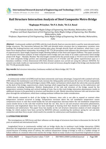
Figure1:PerspectiveviewofBridge
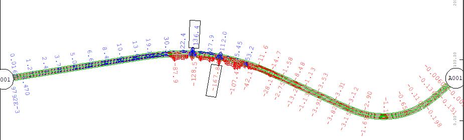
Tocarryoutnumericalstudies RSIofsteelcompositemetrobridge,anumericalmodelhasbeencreatedand theanalysis arecarriedoutusingthismodel.ThemodelcreatedfortherailstructureinteractionhasbeenshownaboveinFig.1.
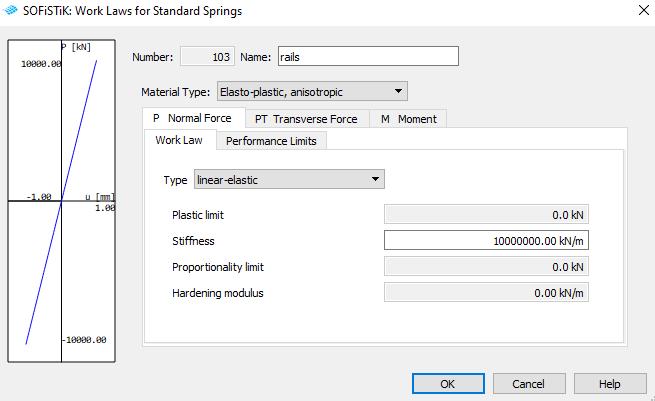
ThenumericalmodelisdevelopedtosimulatetherailstructureinteractionusingthesoftwareSOFiSTiKwhichisbasedon stiffness approach. The bridge and rails are modeled using the beam elements and the connection between the two is modeled by nonlinear springs. The experimental data enabled to idealize the behavior by means of the adoption of a bilinearelasto-plasticlaw,characterizedbythemaximumvalueofthefrictionalforceandthevalueofthedisplacementof yieldu0.AsperUIC774-3R,
Displacementbetweenelasticandplasticzone u0=0.5mm
Resistances k per unit of length for one track in the plasticzone:
-ktr=40kN/mforunloadedtrack(80000kN/m/m)
-ktr=60kN/mforloadedtrack(120000kN/m/m)
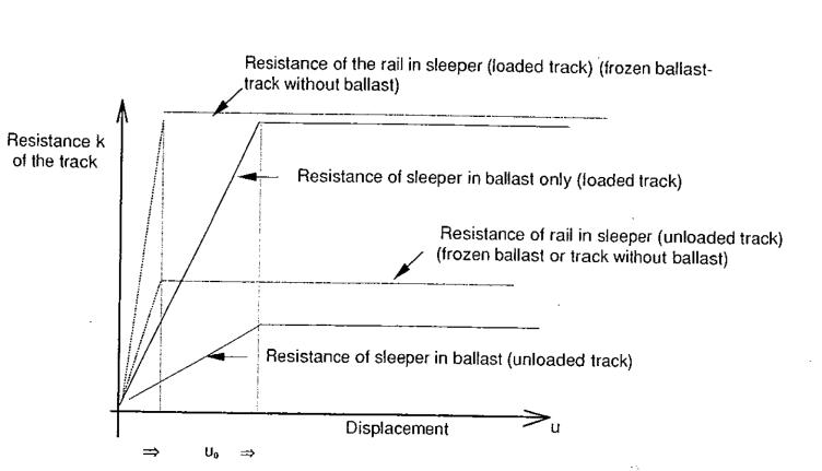
Using the above force displacement diagram, connection between superstructure and rail is modelled as a spring with bilinearelasto-plasticbehaviourintransversedirectionwithstiffnessasshowninbelowfig 3andfig 4
International Research Journal of Engineering and Technology (IRJET) e-ISSN:2395-0056
Volume: 09 Issue: 11 | Nov 2022 www.irjet.net p-ISSN:2395-0072
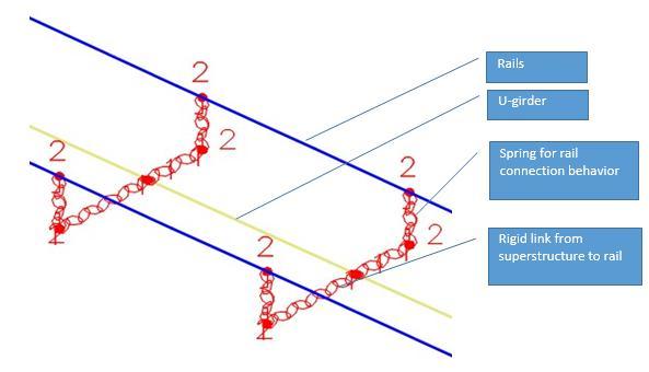
The rail is connected to deck using rigid link and spring as defined above. Typical connection of the rail and U girder superstructureareshownbelowinfig.5
Thebearingsaremodelled usingspring.Inthisstudytwotypesofbearing havebeenused, firsttypeofbearingis POT PTFEfixedandguidedbearingusedbelowsteelcompositeandspecialspansuperstructure andsecondtypeofbearingis elastomeric bearing which is used below standard U girder and I girder superstructure. Bearing is defined in SOFiSTiK usingworklaws
The piercap hasbeen modelledasbeam element. The modellinghasbeen done at thetop ofthe piercap and thepier capisconnectedtothepierusingrigidlinksuptodepthofpiercap.And also,superstructureconnectedtopiercapusing rigidlinksandspringstosimulatetheoffsetandelastomeric/Pot-bearings.
The piles are modelled as beam element, and fixity level is considered at 6m below pile cut off level. The piles are connectedtopiercenterusingrigidlinkstosimulatetherigidpilecap.4pilesperpierhavebeenconsideredforstandard spansand6 piles have been considered for steel compositeandspecial spanin the analysis.Thespacing of the pileshas been considered as 3m in transverse direction and longitudinal direction. For simplicity, the same foundation has been consideredforallpiers.
International Research Journal of Engineering and Technology (IRJET) e-ISSN:2395-0056
Volume: 09 Issue: 11 | Nov 2022 www.irjet.net p-ISSN:2395-0072
As per UIC 774-3, in case of CWR a variation in the temperature of the track does not cause a displacement of the track. Thus,thereisnointeractioneffectduetothevariationofthetemperatureinthetrack.
Thetemperatureloadonsuperstructurehasbeenappliedasperclause1.4.2ofUIC774-3R,whichis±35°C.
Asperclause1.4.3ofUIC774-3R,loadsfromonlytwo tracksaretobeconsidered fortheanalysis.Thesameclausealso specifiesthatbrakingononetrackandtractiononsecondtrackshallbeconsidered.
BrakingandtractioneffectsareappliedalongwiththemovingloaddefinitioninSOFiSTiK.Tobeonconservativesideboth brakingandtractionareconsideredas20%oftheverticalaxleload.
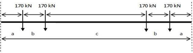
Trafficloadscauseabendinginthedeck.Thisintroducesarotationoftheendsectionsanddisplacementofupperedgeof deck.The effectofthisrotationontherailsistobeevaluated.Asingle6coachtrain with4axlespercoachasdefinedin DBRhasbeenconsideredfortheanalysis.Thefig.6belowshowsaverticalloadofasinglecarofmetrorail.Mumbaimetro hassixnumberofcars;eachcarhasalengthof22.1mandaloadof680kN
appliedinSOFiSTiK
Asperclause1.5.1.ofUIC774-3R,theloadfactorforallloadsshallbe1.
As per clause 1.5.2 of UIC 774-3R, for ballast less track, the additional compressive and tensile stresses in rails due to temperature variation of the deck, barking/acceleration and deck end rotation shall be less than 92 MPa. For this check, theresultsofloadcase1and2willbecombinedwithoutanyloadfactor.
International Research Journal of Engineering and Technology (IRJET) e-ISSN:2395-0056
Volume: 09 Issue: 11 | Nov 2022 www.irjet.net p-ISSN:2395-0072
In this case study the Rail Structure Interaction analysis for Steel Composite Mumbai Metro line 2B rail bridge is performed, and results are represented for individual load. Results for effect of rail continuity on forces transferred to substructureisalsorepresented.
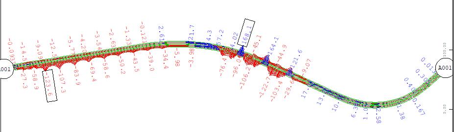
Axialforceinrailduetotemperaturevariationareshowninbelowfigures.
Figure8:Axialtensionforceinrailduetotemperaturevariation
Figure9:Axialcompressionforceinrailduetotemperaturevariation
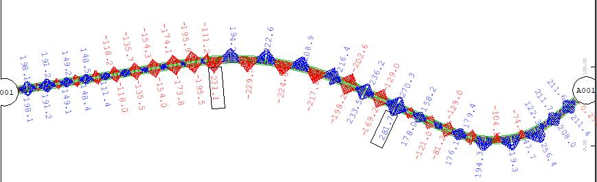
Themaximumaxialtensionforceinrailduetotemperature = 231.1 kN
Therefore,thetensilestressinrailduetotemperature = 231.1 x 1000 7670
= 30.13MPa -Tension
Themaximumaxialcompressionforceinrailduetotemperature = -231.1 kN
Therefore,thecompressivestressinrailduetotemperature = -231.1 x 1000 7670 = -30.13MPa -Compression
International Research Journal of Engineering and Technology (IRJET) e-ISSN:2395-0056
Volume: 09 Issue: 11 | Nov 2022 www.irjet.net p-ISSN:2395-0072
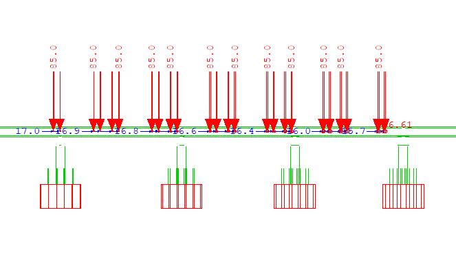
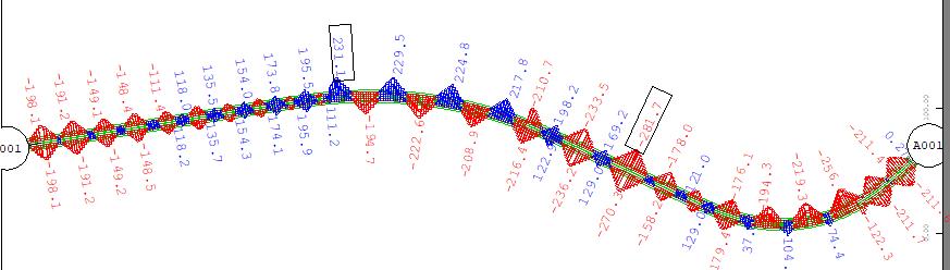
Thecriticalpositionofliveloadforthegoverningforcesinrailforsteelcompositespanisshownbelowfig10.Thecritical caseiswhenbothtracksofthemainlineareloaded.Thisloadtakesintoeffectthelongitudinalforceduetobraking/ tractionandrotationofspanduetoverticalloads.
Figure10:Criticalliveloadpositionforsteelcompositespan
Theaxialforceinrailduetobraking/tractionandverticalliveloadingareshowninthebelowfigures
Figure11:Axialtensionforceinrailduetoliveload
Figure12:Axialcompressionforceinrailduetoliveload
International Research Journal of Engineering and Technology (IRJET) e-ISSN:2395-0056
Volume: 09 Issue: 11 | Nov 2022 www.irjet.net p-ISSN:2395-0072
Themaximumaxialtensionforceinrailduetoliveload = 168.1 kN
Therefore,thetensilestressinrailduetoliveload = 168.1 x 1000 7670 = 21.91MPa -Tension
ThecombinedtensilestressesinrailduetoTemperature&Liveload = 30.13 + 21.91 = 52.04 MPa < 92 MPa
Themaximumaxialcompressionforceinrailduetoliveload = -167.8 kN
Therefore,thecompressivestressinrailduetotemperature = -167.8 x 1000 7670 = -21.87MPa -Compression
ThecombinedcompressivestressesinrailduetoTemperature&Liveload = -30.13-21.87 = - 52.00 MPa < 92 MPa
Table1:Axialrailstressesforpresentstudy
Load Temperature Braking/TractionandVerticalliveload Total TensileStressMPa 30.13 21.91 52.04 CompressiveStressMPa -30.13 -21.87 -52.00
RSIanalysisforpresentstudyshowsthatcombinedaxialtensilestressintherailis52.04MPaandcombinedcompressive stressintherailis52.04MPa.WhicharewithinthepermissiblelimitgivenbyUIC774-3R
Fortheappliedtemperatureloadsasdefinedinloadactionpointno.6,theshearforceineachpierforconsideredspanfor RSIhavebeensummarized below.TheLWR forceto be consideredforanalysisshall betheshearforceobtaineddivided bythecontributarylengthofsuperstructureforthatparticularpier
Table2:LWRforcestransferredtosubstructure
Pier No SpanLength Contributary length Shear Force(kN) Forcepermeter (kN/m)
Preceding succeeding
P465 25m 25m 25m 113.4 4.54
P466 25m 25m 25m 95.3 3.81
P467 25m 25m 25m 82.4 3.30
P468 25m 25m 25m 74.5 2.98
P469 25m 25m 25m 70.4 2.82
P470 25m 25m 25m 70.7 2.83
International Research Journal of Engineering and Technology (IRJET) e-ISSN:2395-0056
Volume: 09 Issue: 11 | Nov 2022 www.irjet.net p-ISSN:2395-0072
P471 25m 25m 25m 74.7 2.99
P472 25m 25m 25m 84.5 3.38
P473 25m 25m 25m 101.2 4.05
P474 25m 43.5m 34.25m 29.4 0.86
P475 43.5m 43.43m 43.46m 12.4 0.29
P476 43.43m 43.5m 43.46m 17.1 0.39
P477 43.5m 43.5m 43.5m 12.9 0.30
P477A 43.5m 43.0m 43.25m 63.3 1.46
P478 43.0m 43.5m 43.25m 129.3 2.99
P479 43.5m 28m 35.75m 244 6.83
P480 28m 23m 25.5m 17.3 0.68
P486 23m 33m 28m 38.9 1.39
P487 33m 33m 33m 101.2 3.07
P488 33m 33m 33m 118.6 3.39
P490 33m 33m 33m 99.3 3.01
P491 33m 25m 19.33m 33.6 1.74 P492 25m 25m 25m 8.43 0.34
ThemaximumLWRforcegeneratedinthepierpermeterrunning=6.83kN/m Themaximumforcepertrackis=3.41kN/m
In the design of substructure and foundation, the LWR force considered is 4 kN/m per track
1. Rail Structure Interaction analysis for this case study shows that combined axial compression and tensile rail stresses duetotemperaturevariationandbraking/tractionandverticalliveloadsare52.00MPaand52.04MParespectively.This rail stresses are within the permissible limit given by UIC 774-3R. Hence no need to provide expansion devices in rail. If stressesexceedpermissiblelimitsgivenbyUIC774-3R,thesestressesarereducedbyprovidingeitherexpansiondevices orchangingtheotherparameterlike,bearingarrangement,deckexpansionlength.
2.Railandstructureinteractionfordifferentactionofloading,transferredhorizontalforces(LWR)tosubstructurewhich is3.41kN/mpertrack.ThisLWRforceshouldbeconsideredforthedesignofsubstructureandfoundation.
1.RDSOGuidelinesVer2forcarryingoutRailStructureInteractionstudiesonMetroSystems.
2.UIC774-3R-Track/BridgeInteraction–Recommendationsforcalculations.
3.UIC776-2R-Designrequirementsforrailbridgesbasedoninteractionphenomenabetweentrain,trackandbridge
4. IRS CBC - Indian railway standard code of practice for plain, reinforced & prestressed concrete for general bridge construction
5.IRSSteelBridgecode-Indianrailwaystandardcodeofpracticeforthedesignofsteelorwroughtironbridgescarrying rail,roadorpedestriantraffic
International Research Journal of Engineering and Technology (IRJET) e-ISSN:2395-0056
Volume: 09 Issue: 11 | Nov 2022 www.irjet.net p-ISSN:2395-0072
6.P.Ruge,C.Birk (2006).Longitudinalforcesincontinuouslyweldedrailsonbridgedecksduetononlineartrackbridge interaction
7.D.R.Widrda,P.Ruge,C.Birk(2008).Longitudinaltrackbridgeinteractionforloadsequence
8. Roman Okelo, Afisu Olabimtan (2011). Nonlinear rail structure interaction analysis of an elevated skewed steel guideway
9. DAI Gong-lian, YAN Bin (2012). Longitudinal forces of continuously welded track on high-speed railway cable stayed bridgeconsideringimpactofadjacentbridges
10. J. Zhang, D.J. Wu, Q. Li (2014). Loading-history based track bridge interaction analysis with experimental fastener resistance
11.AhammedAliAsif,Dr.Raneesh,SisirP.(2016).Strengthproblemsassociatedwithtrackbridgeinteractioninpresence ofcontinuouslyweldedrail
12. S. C. Yang, Senug Yup Jang (2016). Track Bridge Interaction Analysis Using Interface Elements Adaptive to various Loadingcases
13. Alfred Strauss, Saeed Karimi et al., (2017). Monitoring based nonlinear system modeling of bridge continuous weldedrailinteraction
14. Wenshuo Liu, Gonglian Dai, et al,. (2017). Interaction between continuous welded rail and long span steel truss arch bridgeofhighspeedrailwayunderseismicaction
15. Ping Lou, Qiang Wang, FTK Au, et al,. (2019). Finite element analysis of thermal interaction of continuously welded railswithsimplysupportedbridgeconsideringnonlinearstiffness
16. O. R. Ramos, F. Schanack, et al., (2019). Bridge length limits due to track structure interaction in continuous girder prestressedconcretebridge
17.WenshuoLie,HaoLai,ShiweiRaoetal.,(2021).NumericalStudyonTrack-BridgeInteractionofIntegralRailwayRigid FrameBridge
18.XiangdongYu,NengyuCheng,HaiquanJing(2021).AdditionalForcesonContinuouslyWeldedrailoflongspanhigh speedrailwaysuspensionbridgeundersingleeffectandmultipleeffects