International Research Journal of Engineering and Technology (IRJET) e-ISSN: 2395-0056

Volume: 09 Issue: 11 | Nov 2022 www.irjet.net p-ISSN: 2395-0072
International Research Journal of Engineering and Technology (IRJET) e-ISSN: 2395-0056
Volume: 09 Issue: 11 | Nov 2022 www.irjet.net p-ISSN: 2395-0072
Associate Professor, Department of Mechanical Engineering, Vasavi College of Engineering, Ibrahimbagh, Hyderabad – 500 031. ***
ABSTRACT: Savonious rotors continue to interest research investigators in view of its many advantageous features. The simple design of the rotor enables the achievement of a low cost and compact wind power device, although its efficiency may not be comparable with other vertical axis machines such as Darraeus rotor. In wind deficient zones, one can adapt these rotors with success. Different configurations of the Savonious rotor have been proposed to overcome some of the limitations of the earlier Savonious rotors, which have very low tip speed ratios. Design guidelines have been enunciated for the design of the rotors, based on experience with field-installed rotors. Although a few CFD investigations have been reported on the flow analysis of Savonious rotors earlier, there appears to be no serious attempt made earlier for a three-dimensional analysis of flow distribution in these rotors to enable a more realistic understanding of the rotor behavior. In the present paper an attempt is made to carry out a detailed three-dimensional CFD analysis of the basic configuration of the Savonious rotor. A parametric analysis is carried out to understand the performance of the rotor. Comparisons have been made between the results obtained from the three-dimensional analyses with those from twodimensional analysis by the authors and reported elsewhere. The commercially available Fluent version 6.1.2 has been used extensively in the present analysis.
Keywords: Savonious rotor, CFD analysis, wind energy, twinrotor.
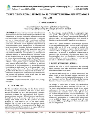
In the present-day philosophy for the design of fluid machinery, flow visualization and flow analysis have become anintegral part. Withthe availabilityof computer simulation software for computational fluid dynamics, many problems, which are difficult to solve, have become tractable to solve. Savonious wind rotors can produce energy from wind power for the purpose of water pumping [1] and electricity [2] at low wind speeds. Although the efficiency is very low, high starting torque and large simplicity in its construction (Fig. 1a&b) and operation have enabled researchers to expend efforts at continualimprovementofSavoniousrotors.
The disadvantages include difficulty of designing for high wind speeds. Although many earlier investigators [3–6] have reported on the design, development and testing of Savonious rotor, very few investigators have reported a detailedthree-dimensionalCFDanalysisoftheserotors.
Cochranetal[7]havediscussedathree-prongedapproach for the design including CFD analyses and wind tunnel testing. Rahai et al [8] have reported a method for aerodynamic optimization to improve the torques in split Savoniousrotors. Inthepresentpaper,anextensivethreedimensional CFD analysis of a practical configuration of Savoniousrotoriscarriedout.Thetheoreticalresultsfrom the analysis have been correlated either with those from windtunneltestsbyearlierinvestigatorsorwithreported testdataonactualrotorsinsiteconditions.
Based on the work of earlier researchers, the following design guidelines have been documented in the previous publicationsandaregivenbelow.
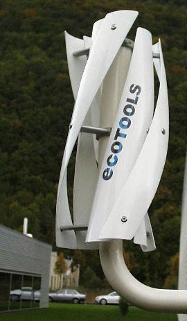
(1) The size of the end plates, to which are mounted the bucket,shouldbeabout5%largerthanthediameterofthe rotor. (2) The central shaft should be mounted to the end plates only, and not through the buckets. By keeping theshafttotheendplates,theairspaceisnotblocked.
For example, a central shaft of about 20% of the rotor diameter reduces the power coefficient by about 8%. (3) The aspect ratio, height to diameter; 6 to 8 gives a better performance. However, an aspect ratio of about 2 is desirable from the economic point of view. (4) Use only two buckets as higher number reduces the efficiency. (5) Use of augmentation devices such as concentrator or diffuser or a combination of the two results in increased power coefficient. Again, the increased costs of such devices should be weighted against the increased capital costandcomplexities.
e-ISSN: 2395-0056
Volume: 09 Issue: 11 | Nov 2022 www.irjet.net p-ISSN: 2395-0072
inside the vanes and in the near vicinity of the rotor. The wind is assumed to comprise of pure air under standard conditions of temperature of 20 oC, density of 1.19 N/m3 . The velocity regime considered in the present work is 6 m/s,whichvalueisimposedasa boundarycondition,ina directionnormaltotheaxisoftherotor.
(b) (c)
Athree-dimensionalanalysisoftheSavoniousrotorhaving two 0.4m-diameter vanes and without vane offset (e=0 in Fig 1a) is carried out using the computational fluid dynamics approach. The need for carrying out a threedimensional analysis as an extension to the earlier twodimensionalanalysesofthepresentandotherauthorsisto understand thefluid flowaspectsnearthe endclosures of thevanesoftherotor(Fig1a)inadditionto flowbehavior
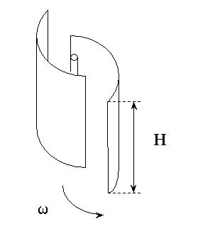
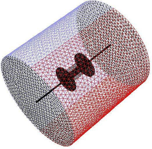
Gambit software is used as the pre-processor for constructing the geometry, mesh building and assigning the boundary zones on the geometry of the Savonious rotor. A three-dimensional geometry is used for simulation, with area of interest as a circular boundary of radius,1.5 m. The bladesof the Savonious rotor are taken as a semi-circular shape with radius 0.2 m with no offset. Here two vanes are used on the rotor, which are placed adjacenttoeachotherbutfacinginoppositedirection.The domain is meshed with tetrahedral elements and the critical region is densely meshed. The velocity inlet and pressure outlet boundary zones are assigned, and the model is exported to fluent, which is used for solving and post processing. A segregated 3D implicit model is used and the fluid, air, properties are assigned. The governing conservationofmass,momentumandturbulentequations are discritized using second order upwind scheme and pressure velocity coupling equation is represented with SIMPLE algorithm. Fig.2. shows the typical configuration and the mesh of the rotor without vane offset. An earlier investigation has revealed that the k- model is the preferred model for simulating turbulence and the same has been used in the present analysis. Appropriate convergence criteria have been utilized to check the results.
Fig.2. MeshforSavoniousRotorwithouteccentricity
International Research Journal of Engineering and Technology (IRJET) e-ISSN: 2395-0056
Volume: 09 Issue: 11 | Nov 2022 www.irjet.net p-ISSN: 2395-0072
The velocity and static pressure distributions at the mid-planeoftherotoraregiveninFig.3.
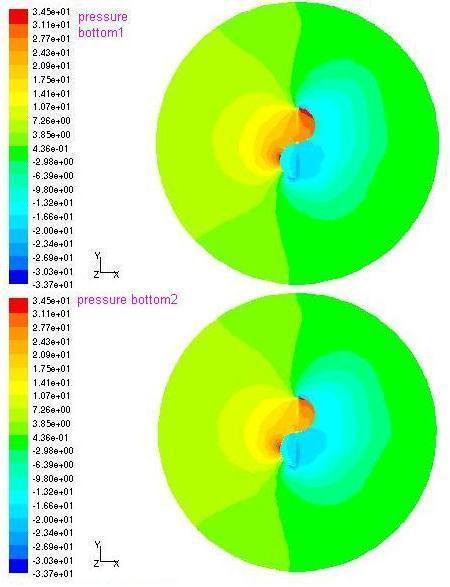
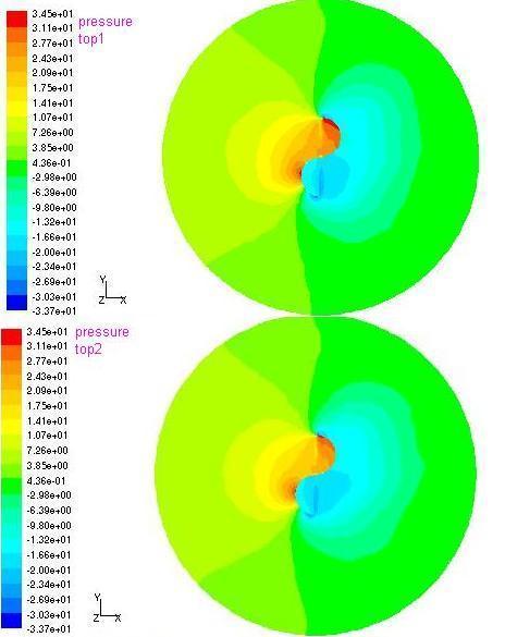
The contours for velocity and static pressure in planes perpendicular to the vanes atlocations of the rotor as per the scheme in Fig. 4 are shown in Figs. 5 and 6 respectively. It can be observed from these contour maps that they exhibit an excellent symmetry of the results aboutthemidplaneoftherotor.
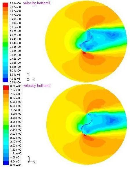
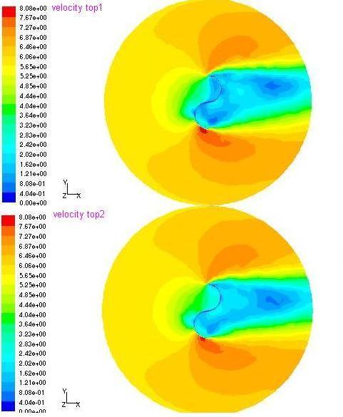
Fig.3. Three-dimensionalanalysisoftheSavoniousrotorResultsforthemid-planeoftherotor.
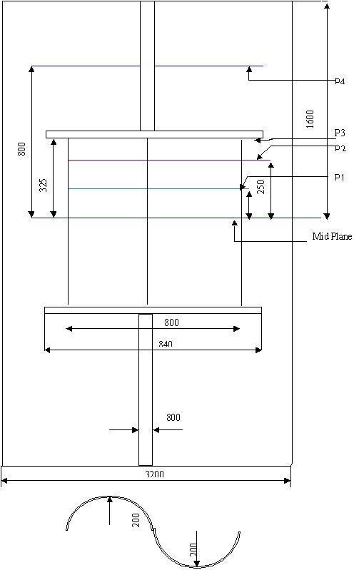
Fig.4 shows the sections on the Savonious rotor at which results for the velocity and pressure distributions are discussed.
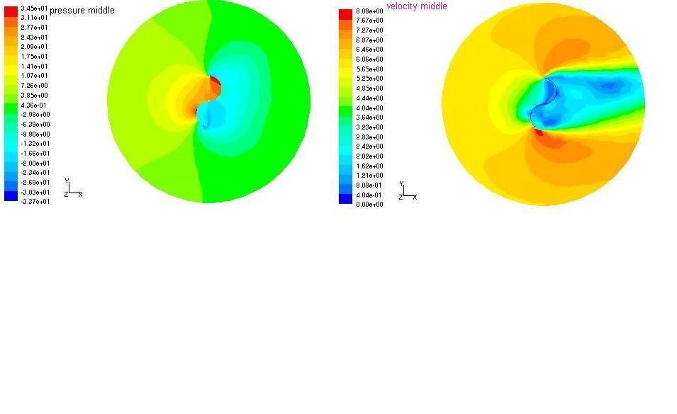
Fig.4. LocationofSectionsonSavoniousRotorfor discussingtheresults
Fig.5.Contoursofvelocityatcross-sections1to4.
2395-0056
2395-0072
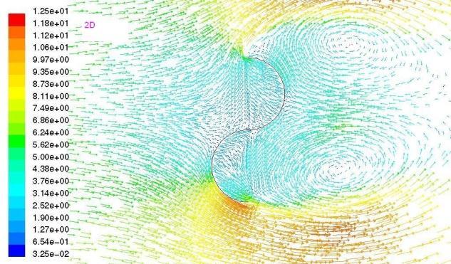
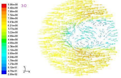
Fig.7.Comparisonofthevelocitiesatthemid-plane
Thevelocitiesarebetterunderstoodbyobservingaplotof velocityvectorsasshowninFig.7.Itcanbeobservedthat the2Danalysisyieldsavalueofaround2.42m/swhilethe 3Danalysisgivesavalueof2.49m/sattheinletvane.
A three-dimensional analysis of Savonious rotor has been carried out in the present analysis. The results obtained are compared with those from the 2D analysis of the earlier investigators and the deviations in the velocities andpressureshavebeenhighlighted.
[1]. F. Gardelle, 2000; “etude experimentale d'une eolienne savonius en soufflerie atmospherique Manuel d'utilisation de PIVIS”. IMFT Service Signaux et Images du département électrotechniquedel'ENSEEIHT,France.
[2]. Mganilwa,Z.M,“DevelopmentofaSavoniusWind TurbineWaterPumpingSystem,TechnicalReport of the Department of Mechanical Engineering”, DaresSalaamInstituteofTechnology,Tanzania.
[3]. N.Fujisawa,F.Gotoh1992;“Visualizationstudyof the flow in and around a Savonious rotor”. ExperimentsinFluids12pp407~412
International Research Journal
Engineering
Technology (IRJET) e-ISSN: 2395-0056
Volume: 09 Issue: 11 | Nov 2022 www.irjet.net p-ISSN: 2395-0072
[4]. M.A. Kotb, T.K. Aldoss 1991; “Flow field around a partially-blocked Savonious rotor”. Applied Energy38pp117~132
[5]. N. Fujisawa, K. Ishimatsu, K. Kage 1995; “A comparative study of Navier-Stokes calculations and experiments for the Savonius Rotor”. Journal ofSolarEnergyEngineering117pp344~346
[6]. D.Benghrib,A.Ahram,L.Bchir1998;“Description del'alternancedestourbillonsd'unrotorSavonius par visuatisation en tunel hydrodynamique”. Compte Rendu de l'Académie des Sciences, Tome 326,SérieII,pp495~500
[7]. Cochran. B.C., D. Banks and S.J. Taylor, “A threetiered approach for designing and evaluating performancecharacteristics ofnovel wecs”.AIAA2004-1362.
[8]. Rahai.R. Hamid, Hefaiz Hamid, “Energy innovations small grant (EISG) program”, grant#: 00-17
[9]. N. Fujisawa 1995; “Velocity measurements and numerical 2calculations of flow fields in and around Savonius rotors”. Journal of Wind Engineering and Industrial Aerodynamics 59 pp 39~50
[10]. V.J. Modi, M.S.U.K Fernando 1989; “On the Performance of the Savonius Wind Turbine”. JournalofSolarEnergyEngineering111pp71~81
[11]. Job S. Ebenezer, Savonius windmill, Report of the Department of Messiah College, Grantham, PA 17027
[12]. Fluentuser’smanual