International Research Journal of Engineering and Technology (IRJET) e-ISSN: 2395-0056

Volume: 09 Issue: 10 | Oct 2022 www.irjet.net p-ISSN: 2395-0072
International Research Journal of Engineering and Technology (IRJET) e-ISSN: 2395-0056
Volume: 09 Issue: 10 | Oct 2022 www.irjet.net p-ISSN: 2395-0072
1PG Student,2Associate Professor & Chairman,3Assistant Professor,4Director-Aerospace R&D, 1-3Department of Aerospace Propulsion Technology, Visvesvaraya Technological University -Centre for Post Graduate Studies, Bengaluru Region, VIAT, Muddenhalli, Chikkaballapura, Karnataka, India.
4Dautya Aerospace Pvt Ltd, Bengaluru, Karnataka, India. ***
Abstract - Cross wind effect is one of the biggest challenges faced by aviation industries this is due to poor braking efficiency as one of the biggest factors. Today in aircraft operation of breaking especially during landing we are using the support of spoiler, thrust reversal, flap to create lift After having different braking systems still this problem is existing where the aircraft encounters runway excursion, landing gear failure and crush As a solution for this problem slat diploid braking system can tremendously reduce the lift produce by increasing the drag in order to improve the braking efficiency
Key Words: Slat, crosswind effect, Drag.
Themainobjectiveoftheprojectistoreducethecrosswind effectthatimpactstheaircraftatthetimeoflandingandin specialcasesduringtake-offalsopresentdaysaircrafthave thrustreversal,spoiler,andflaptocreatedraginspiteofall theothercontrollingsystemwestillfacingthefailureofsafe landingduringthetimeofcrosswindandalsodelayingthe landing time which causes a lot of loses to the aviation industriesduetopoorlandingorbrakingefficiencythemore fuelitconsumes.
Anothermajordrawback isthatinthedomesticplanethe passengerfeelslesscomfortableduringthetimeoflanding due to poor landing or braking efficiency. Sometimes the aircraft get damaged due to the failure of the braking efficiencysowecomeupwithasolutionthroughthedesign andanalysisofaslatthatcanbeusedtoincreasethebraking efficiencyintheaircraftduringthelanding.
Anotherproblemwasaircraftusuallytakealargerspaceto landtherewasnoefficientsystemforshort-distancelanding. our project will also be the solution to this problem. the short-distancelandingsavestimeandfuelconsumptionand theareaoflandthatcanbeusedforotherpurposes.
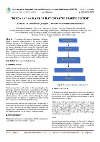
Theprojectcarriedoutwouldundergothefollowingstepsof workallthesimulationandtheanalysis.
Fig -1:flowchartofthestepsoftheproject
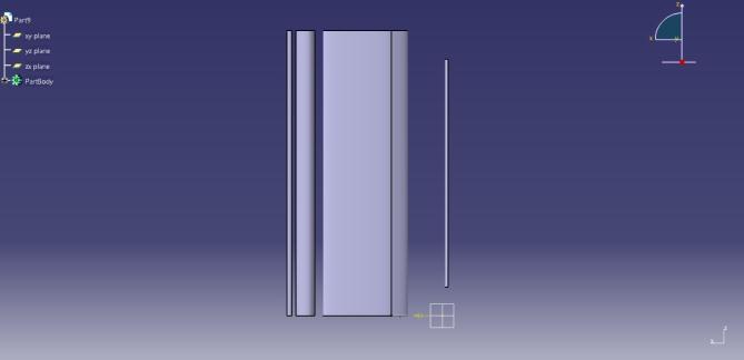
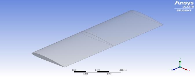
In designing the airfoil we used the NACA2412 series slat placedbefore theairfoilAsshowninfig2asitslooksafter designingthemodelinCATIAimportedthemodeltoAnsys softwaretofurtherprocess
CATIA is a well-known software for design it is more convenienttousethissoftwarefirststepisfromtheNACA toolwehavetodownloadthecoordinateoftheairfoilimport toCATIAreadableformthenbythecoordinatewehaveto designtheairfoilthroughthesamedesignastouseforboth slatfig3andwithoutslatmodel afterfinishingthedesign savethefileinisgformate
ansysisthemostpopularsoftwarefortheanalysisoffluent, thermal,andalsosomeotherconditionsweareusingAnsys for our project to verify the modified model to check the behaviouroftheforcesthatactontheairfoil
International Research Journal of Engineering and Technology (IRJET) e-ISSN: 2395-0056
Volume: 09 Issue: 10 | Oct 2022 www.irjet.net p-ISSN: 2395-0072
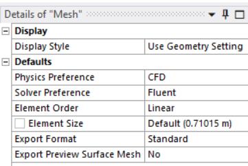
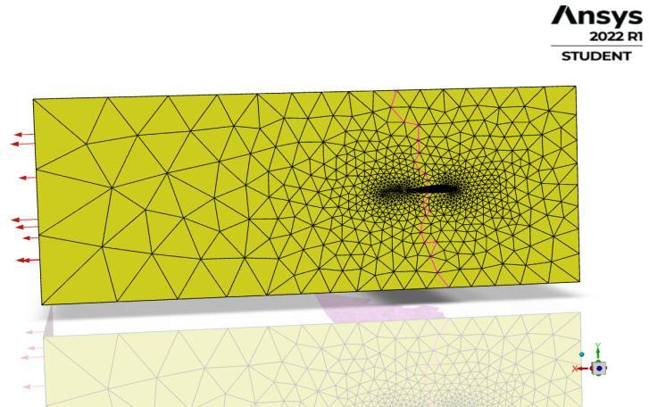
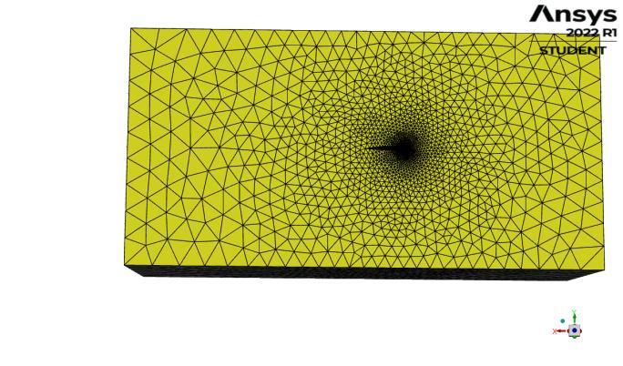
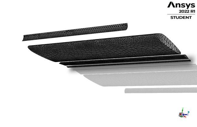
Inthemeshingselecttheelementsize 2mtosetselectface mesh then select all the planes of the model to uniform meshingonthesurfaceofthemodelthenselectthegrowth rateas1.1inthemeshsetupclickthegenerate belowfig5is themeshingofthewithoutslatmodelandfig6denotesthe withslatmode
MeshingisaveryimportantpartofCFDsimulation.Without a proper mesh, will not be possible to get a converged solutioninthisprojectmeshinghasbeendoneusingANSYS meshingfeature.
Initially,themeshwascheckedforanymappablefeasibility. Thisinitialoverviewgivesusaroughideaofhowourmesh wouldbe.Accordingtothisnecessarymesh,controlcanbe doneaccordingtothesurfaceorbodytype.Acontroltothe extentofmanagingthenumberofelementstobepresentat thespecificedgeorfacecanalsobemanagedthroughmesh control.
Fig -5:Meshingof Airfoilwithoutslat
Fig -6:Meshingof Airfoilwithslat
International Research Journal of Engineering and Technology (IRJET) e-ISSN: 2395-0056
Volume: 09 Issue: 10 | Oct 2022 www.irjet.net p-ISSN: 2395-0072
OnstartingtheFLUENTsetup,theFLUENTlauncherappears providingoptionswith2D/3Dmodelbasedonthegeometry modelandoptionslikedoubleprecision,displaymesh,etc, Additionally,thelauncheralsoenablestheusertoselecta number of processors that are being dedicated for the FLUENTprogram.Theusercanalsosetupasshowninfig 7additionalcoresoftheDedicatedcorebasedonthemodel complexity.
After the setup of the solution after selecting the report definitioninthatselect,theforceofliftanddragcoefficient thencreatethereportdefinition.Afterthereport,thesetup computes the solution from the inlet of the model selects initialization Then clicks on the standard initialization afterwardclicksoncomputefromtheinlet.referanceframe astobeabsolute
Clickoninitializationaftertheinitializationclicksontherun calculationinthismodulesetthe500iterationsandthenset theinterval 10after clickingon run. afterclickingthe run system take time to compute the graph of lift, drag, and residualgraphafterthatgototheresultandselecttheplane tocreateaplaneontheXYplane,createacounter selectthe plane, and the wing region select the static pressure as to showclickonsaveandplotasshowninfig
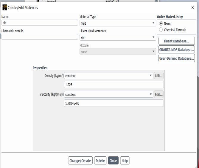
Afterthemodelsetupmoveandselectthematerialinthe material select air set the viscosity and density of the material as te constant and density is 1.225 than click change asshowninfig-8
The mesh will be automatically loaded into the setup and createsautomatedpartitions,zone,andnecessaryboundary condition which will include our named selection that we have created in the meshing stage. The first step to being done upon loading the mesh into the FLUENT setup is to check the mesh integrity loaded onto the setup. This is a preliminary check that has to be done in order to avoid errors(incase)inthelatestage.
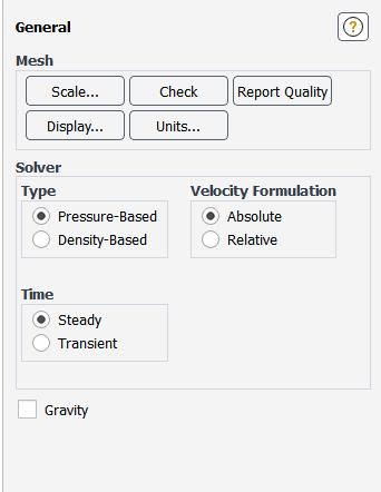
Click the check button in the general settings of the task planeandwaittillitmessageappearsontheconsoleofthe client whichstatesthemeshhas noerrorandthesetup is carriedforward.
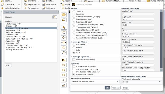
Thenwewillconfigurethemodelthatistobeconsideredfor thesetupsi.e.,Energy,Viscous,andspeciesmodel.viscous SST k omega then click the komega 2eq then click ok is showninfig8
After the material setup go to the solution method in the sostepwiselect theshownhostepwisese is as shown in the figureselectthegradientasleastsquarenodebasedandthe pressure as second-order momentum as second-order upwind turbulent kinetic energy as second-order upwind schemeassimple
International Research Journal of Engineering and Technology (IRJET) e-ISSN: 2395-0056
Volume: 09 Issue: 10 | Oct 2022 www.irjet.net p-ISSN: 2395-0072
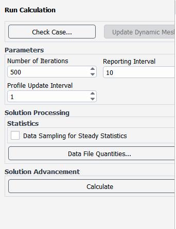
Run calcution taskbar we have to enter the number of iterationas500 andreportintervalas10asshowninfig9
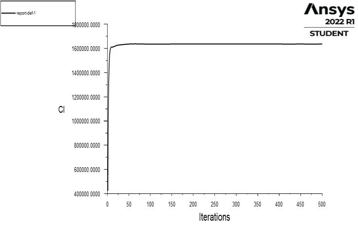
Afterthecomputationbycomparingourmodelairfoilwith slatagainstthemodelinwhichnormalairfoilfig10clgraph isshowingthattheliftisincreasinginwithoutsaltornormal airfoil but in our model fig11 lift is going decreases aswe computedthegraph.Fromthisgraph,wecansaythatour modelhasachievedtheobjectiveoftheproject
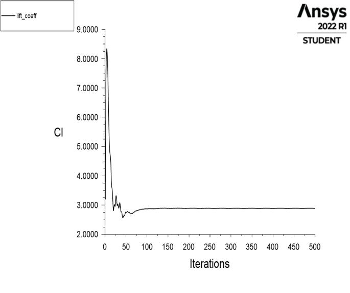
Inthe belowgraphfig7.1of themodel withoutslatmodel showsthattheliftcoefficientincreasesfortheiterationof 500 readingsx-axisistheliftcoefficientandyisthenumber ofiterations.
Afterthesetupofthesolutionafterselectreportdefinitionin thatselect,theforceofliftanddragcoefficientthencreate thereportdefinition.Afterthereport,thesetupcomputes thesolutionfromtheinletofthemodelselectsinitialization Thenclicksonthestandardinitializationafterwardclickson computefromtheinlet.referanceframeastobeabsolute.
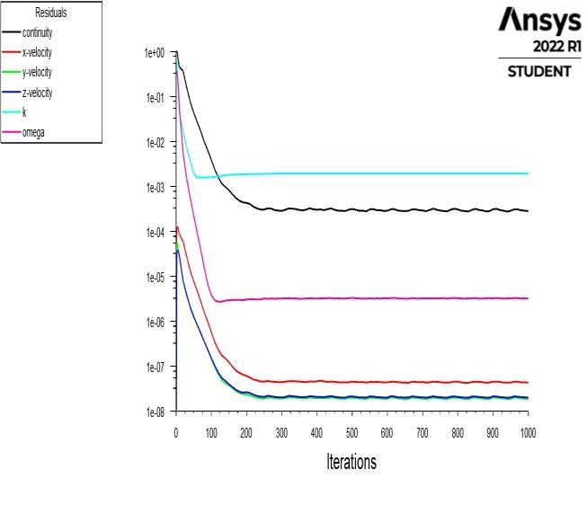
Clickoninitializationaftertheinitializationclicksontherun calculationinthismodulesetthe500iterationsandthenset theinterval 10after clickingon run. afterclickingthe run system take time to compute the graph of lift, drag, and residualgraphafterthatgototheresultandselecttheplane tocreateaplaneontheXYplane,createacounterselectthe plane, and the wing region select the static pressure as to showclickonsaveandplot
Betweenthesolution andinitializingthesoultion,there is anothersetisreportpotswehavetodefinetheclandcdto bepostedasaresult.
Fig -11 coefficientofliftwithoutslatmodel
Fig -10 Runcalculationsetuptaskbar
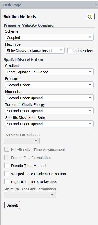
Fig -12 coefficientofliftwithslatmodel
International Research Journal of Engineering and Technology (IRJET) e-ISSN: 2395-0056
Volume: 09 Issue: 10 | Oct 2022 www.irjet.net p-ISSN: 2395-0072
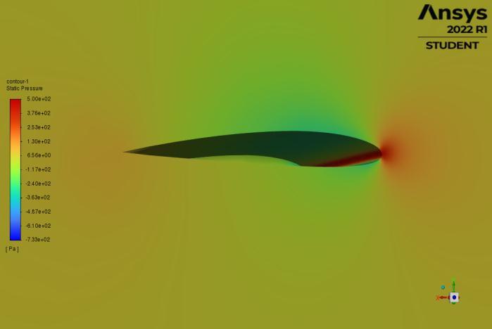
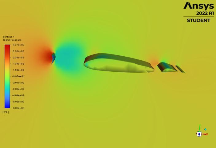
From the above pressure distribution of both, our model fig14versusthenormal airfoilmodel pressuredistribution around the normal airfoil fig15 ismorecomparedit with ourslatmodelduetothedirectcontactofairforcepressure ismoreatthenormalairfoilbutinourmodel
Pressureiscutoffbytheslatwhichincreasestheefficiency inthebrakingsystemoftheaircraftandalsohelpswiththe saferlandingandalsoshortdistancelandingofaircraft
Thisproject’smainobjectiveistoreducetheliftforceofthe aircraftduringthetimeof crosswindeffectontheaircraft landingmovement.Reducethecrosswindeffectandallows theaircrafttosmoothandsafelandingasperourobjective the lift is considerably decreased. while the without slat modelhasgeneratedtheliftbythisresultwecanconclude thattheexperimenthasshownapositiveresulttowardsthe objectiveoftheprojectthisresultcanbenotonlyapplicable duringthecrosswindeffectbutalsointhetimeoffailureof anothercontrolunit
This slat model can also be used for the short-distance landingofaircrafttherebyreducingthetimeoflandingand also the fuel consumption of the aircraft. And the space required during the landing. After the project outcome further, we have test the model on WindTunnel for more confirmationandalsorectifiestheproblemwhatarefaced duringthelandingoftheaircraft
Theprojectasgivesapositiveresulttowardstheobjective. satisifiedthecondition hasnow
[1] ”DragAssessmentofaHighPerformanceAircraftusing System Identification Techniques” Khadeeja Nusrath, Jatinder Singh and Basappa National Aerospace Laboratories,CSIR,Bangalore-560017,India
[2] Crosswind Landings in General Aviation: A Modified MethodofReportingWindInformationtothePilotMatt Ebbatson, Don Harris, and Steve Jarvis Department of Human Factors Cranfield University, Bedford, United Kingdom
[3] The effect of flap-end additions on aircraft trailing vortices W. R. Graham and T. Berteny Department of Engineering, University of Cambridge, UK L. David Laboratoire d’Etudes Aérodynamiques, Université de Poitiers,France
[4] EffectofLeading-EdgeSlatsatLowReynoldsNumbers Lance W. Traub and Mashaan P. Kaula †Aerospace Engineering Department, Embry Riddle Aeronautical University,Prescott,AZ86301,USA;
International Research Journal of Engineering and Technology (IRJET) e-ISSN: 2395-0056
Volume: 09 Issue: 10 | Oct 2022 www.irjet.net p-ISSN: 2395-0072
[5] Aircraft Braking System 1Shruti Nair, 2Shreya Nair 1,2Dept. of Mechanical and Automation Engineering, Indira Gandhi Delhi Technical University for Women, Delhi,India
[6] Wind-tunnel and CFD investigations of UAV landing gears and turrets – Improvements in empirical drag estimationFalkGöttena,b,∗,MarcHavermanna,Carsten Brauna,MatthewMarinob,CeesBilbaDepartmentof AerospaceEngineering,FHAachenUniversityofApplied Sciences,Hohenstaufenallee6,Aachen,52064,Germany bSchoolofEngineering,RMITUniversity,264PlentyRd, Bundoora3083,Australia
[7] Wind-tunnel and CFD investigations of UAV landing gears and turrets – Improvements in empirical drag estimationFalkGöttena,b,∗,MarcHavermanna,Carsten Brauna,MatthewMarinob,CeesBilbaDepartmentof AerospaceEngineering,FHAachenUniversityofApplied Sciences,Hohenstaufenallee6,Aachen,52064,Germany bSchoolofEngineering,RMITUniversity,264PlentyRd, Bundoora3083,Australia
2022, IRJET | Impact Factor value: 7.529 | ISO 9001:2008 Certified