International Research Journal of Engineering and Technology (IRJET) e-ISSN: 2395-0056

Volume: 09 Issue: 10 | Oct 2022 www.irjet.net p-ISSN: 2395-0072

International Research Journal of Engineering and Technology (IRJET) e-ISSN: 2395-0056
Volume: 09 Issue: 10 | Oct 2022 www.irjet.net p-ISSN: 2395-0072
1 M.Tech Scholar, Dept. of Civil Engineering, Shri Rawatpura Sarkar University, Raipur
2 Assistant Professor, Dept. of Civil Engineering, Shri Rawatpura Sarkar University, Raipur
3 Assistant Professor, Dept. of Civil Engineering, Shri Rawatpura Sarkar University, Raipur
4 Assistant Professor, Dept. of Civil Engineering, RSR Rungta College of Engineering and Technology, Bhilai ***
Abstract - Shells with various shapes are being studied. B. Elliptical hemispherical, conical, and cylindrical shells. These structures usually fail by spasming with external pressure. Cylindrical steel silos are large, slender structures used to store materials such as cement, grain, flyash, soot, and coal sawdust. Theyare specializedstructures,subject to a variety of unconventional loading conditions ranging from tons tohundredstothousandsof tons,leadingto unusual failure modes. The main purpose of this work is to extend our currentknowledgeof silo strengthand buckling/collapse. In particular, referring to the construction of steel silos on individual supports, itis toprovide practicaland valuable design assistance for the design and construction of futuresilos, andtodevelopnew ones.Investigative aspects for further investigation. In this work, steel silo structures were considered according to literature data and different shear wall curvatures wereapplied. Themethod applied inthiswork is ResponseSpectrumAnalysis,a robustdynamicanalysistool inSTAAD.Pro.The currentstudycompares thelateralanalysis ofsteelsilo structures with differentmodeltypesandprovides the best compared to specific structure types and literaturebased structures.
Containers forstoringbulkmaterialsarecommonlycalled bunkers,bunkers, silos,or tanks.Althoughthereareno generally accepteddefinitionsfor each of these terms, shallowbins such ascoal, coke, ore, crushed stone,and gravelare often called bins or bunkers, andare used to storematerials such as grain andcement. Tall binsare usuallycalledsilos.Inthiswork,siloisagenerictermforall steel structures forstoringbulkmaterials. The steelsiloisprimarilyamuchlighterstructure,canbequickly assembledanddismantled, carriesloadsthrough variousstructural mechanisms,and deforms easilyand reversiblywhensubjectedtounbalancedloads.Andunlike concretesilos,theloadonthefoundationisless.Steelsilos arethereforewidely used forshort-termand long-term storage of largeamountsof bulkmaterialsandare increasingly beingbuilt in recent years in many industriessuch asmining, chemical, power generation,
agricultureandfoodprocessing.Commonsteelsilos[29]are usuallycircularincross-sectionandmaybeabovegroundor elevated.Atypicaltowersilogenerallyconsistsofaconical roof,acylindricalshellandaconicalhopper,whichcanbe supportedbyasupporting apronorseparatesupports. Theconnectionbetween vertical wall andfunneliscalledtransition.The transitionis usually providedwitharigidring.Inpractice,therearemanyforms ofsupport,whichlocallycontacttheshell,andwhichmaybe describedasdiscretesupports.Columnsofvariouswidths havebeenwidelyusedassupportsandthesemayterminate belowthetransitionjunction,extendtotheeavesorengage into the shell for a short distance. In this work, the term ‘discretely supported silo’ is used to mean that the silo cylinderisdirectlysupportedonlocalsupportsofadefined width
International Research Journal of Engineering and Technology (IRJET) e-ISSN: 2395-0056
Volume: 09 Issue: 10 | Oct 2022 www.irjet.net p-ISSN: 2395-0072
engineers.Toolsforsteelconstructionareplentifulandfar moreadvancedthantoolsforothersystems.Fullintegration between analysis, design, detailing and manufacturing softwareisnowused.Sustainabilityisthemiddlenamefor structuralsteel.Mildsteelisthemostrecycledmaterialon earth.Today'smildsteelconsistsof88%recycledproducts andinthefutureitwillbefullyrecyclableandcanbereused withoutfurthertreatment.Structuralsteelbuildingscanbe modifiedforfuturenewapplicationsandloadingconditions, verticalexpansionandchanges.Atypicalsteelcolumntakes up75%lessfloorspacethanacomparableconcretecolumn.
TYPES OF SILOS:-
Cement Storage Silos
Tower Silo
Industrialbuildingsaregenerallydesignedasenclosures that provide functional space for internal activities that involvetheuseofoverheadcranesandoverheadequipment. Variousformsofconstructionhavebeendevelopedoverthe last 30 years to optimize the cost of steel construction in relation to the space provided. Moreover, their design is highlystandardizedaroundtheworld,whichposesadifficult probleminthecontextofindustrialriskassessmentsrelated to external hazards such as earthquakes and wind. Their dynamic response is non-trivial given the associated susceptibilitytoinfluenceearthquakedamage.Bulkmaterial storage is therefore an important aspect in any industrial building. Mild steel is manufactured in workshops, which makesconstructionmoreproductive.Integrationintoother buildingsystemsandrapidassemblyatanytimeoftheyear withminimalon-sitewasteisachievableonlywithstructural steel.Architectscelebratethenaturalbeautyofsteelandlook forwardtoincorporatingitintothedesignofstructuresto emphasize the elegance, slenderness, strength and transparencyoftheframe.
FreeExpressionNootherframematerial matchesmild steelinitsabilitytoencouragedesigncreativity.Mildsteel continues to be the most desirable material for civil
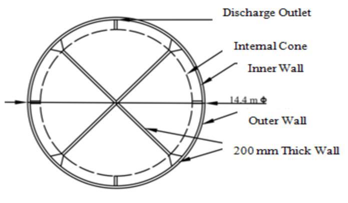
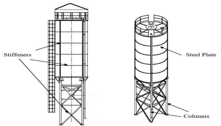
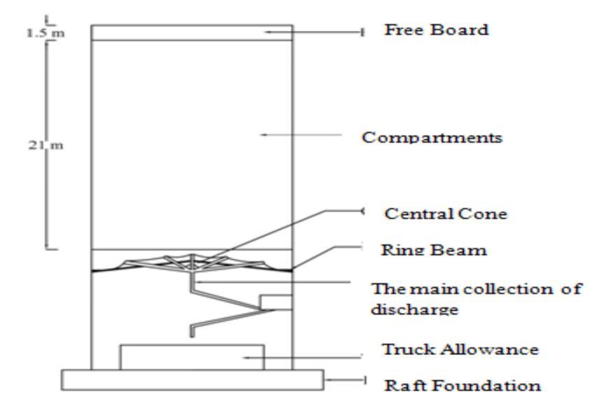
Figure 1.1.1 Elevationand3-Dviewoftypicalsilo structure
Silosaresubjectedtodifferenttypesofshocksandloads As per Indian Standard Code, IS: 875: 1987 Part I-V, the followinglistofloadsaretobetakenforsilo: weightofstructuralmaterial StorageMaterialWeight RoofandFloorForce Windload
Imposedloadsanddeformationload
Assilosareexposedtodifferentloadconditions,different failuremodescanoccur.Nevertheless,acriticalstateofwall stress usually ultimately leads to one of the few failure modes.Thesecanbebrieflylistedasfollows:
For the cylindrical shell bursting
1.Bucklingunderaxial(vertical)compression 2.Hoop(ring)bucklingundercompression 3.Membraneshearbuckling
4.Localcollapsenearsilosupport
International Research Journal of Engineering and Technology (IRJET) e-ISSN: 2395-0056
Volume: 09 Issue: 10 | Oct 2022 www.irjet.net p-ISSN: 2395-0072
1.Collapseorburstofhopperbody 2.Plasticcollapseorburstofhopper/ringconnection 3.Fortransitionring 4.Bucklingofthetransitionring 5.Plasticcollapseofthetransitionring
6.Directsupportatlocalsupportsofdefinedwidth.
1. TransitionRingBuckle
2. plasticcollapsationofthetransitionring.
Severalrepresentativesiloshavebeendamagedorcollapsed inrecentearthquakesaroundtheworld.Earthquakesoften causesilodamageand/orcollapse,resultinginsignificant economiclossaswellaslossoflife.Seismicgroundmotion has three components and produces two structural loads: verticalandhorizontal.Theeffectsofverticalseismicloads onrelativelyheavysilodesignsareusuallysmall,whilethe effects of lateral loads can be significant, especially in tall silos containing heavy materials. Horizontal seismic load magnitudeisdirectlyproportionaltotheweightofthesilo. Thehigherthesiloheight,thehigherthecenterofgravityof thesilostructure.Assumingthatthehorizontalseismicload isappliedapproximatelyatthecenterofmass,themoment armofthelateralloadandcorrespondingbendingmoment at the base will increase. The increased bending moment results in an uneven distribution of pressure on the silo floor,whichcanbesignificantlygreaterthanthepressure duetogravity.Anearthquakecanalsodamagethetopofa silo if the materials contained in the silo are allowed to vibrateinsidethesiloduringanearthquake
Rotter (1990) [1] describedtheresultsofastudyonelasticplastic collapse of axially loaded internally pressurized perfectthincylindricalshellsadjacenttotheshellsupport. Thefailuremodeoftenknownas"elephant'sfoot"buckling which governs the design of many practical bin, silo, and tankstructureswerestudied.Theresultsarecomparedwith previous design recommendations and a new simple equationisproposedforuseindesign
Alauddin and Ahmad (1995) [3] didfullscaleanalysisof circularsilohavingdifferenttypesofsupportsandsubjected tovariousloadingconditionsrevealedthattheconventional method is not adequate in predicting the values of stress resultantsrequiredfordesignofasilo.
Teng (1997) [4] investigatedtheeffectsofvariousfactors ontheplasticout-of-planebucklingbehaviorandstrengthof ringbeam,leadingtotheeventualdevelopmentofasimple plasticbucklingapproximation for design use. Anannular plate ring beam at the transition junction of a uniformlysupported steel silo or tank is subject to a large circumferential compressive forcederivedfromthe radial componentofthemeridionaltensionintheconicalhopper. Underthiscompressiveforce,theringbeammayfailinone ofseveralpossiblemodes,includingout-of-planebuckling.
Croll (2006) [5] whenthincylindricalshellwallsoftanks and silos are subject to combinations of internal pressure andaxialcompression,localformofbucklingfailureoccur. They are axis symmetric and influenced by the end or intermediate support conditions. This paper outlines the basis of an analytical solution to the inherently nonlinear elastic–plasticbucklingintoaxisymmetricmodes.
Bischoff (2008) [6] 3-Danalysesofshellscomparing3Dshell foundations, three dimensional solid elements and surface-orientedshellformulationweredone.Comparisonis madewiththeoreticalformulation,finiteelementtechnology andconsistency.Advantagesanddrawbacksofthedifferent conceptsarediscussed.Distinguishedthecaseofthinshells, werelockingeffectplayapredominantroleandtheanalysis of 3D structure. A dilemma appeared, it is impossible to designanelementwhichis completelyfreeoflockingand passesthepatchtestatthesametime.
Dash and Raju (2008) [7] studiedthebuckingbehaviorof compression loaded composite cylindrical shells wit reinforced cut-outs by ANSYS. They consider composite loaded composite cylindrical circular shells for buckling analysis. The effect of cut-outs and how their position influencesthe bucklingstrengthoftheshell werestudied. Thepresenceofcutoutscanincreasethedeformationand stressconcentrationaroundit.Also,criticalloadingcanbe increasedbyreinforcingthecutouts.
International Research Journal of Engineering and Technology (IRJET) e-ISSN: 2395-0056
Volume: 09 Issue: 10 | Oct 2022 www.irjet.net p-ISSN: 2395-0072
SteelSiloWallThickness 10mm–40mm
TotalHeightofSteelSilo 11.5m
SiloCylinderDiameter 1.6m BehaviourofMaterial IsotropicandElastic Young'sModulus 21000MPa Poisson'sratio 0.3 massdensity 7800kg/m3
The loading on the structure is considered as per following calculations
UnitweightofIronores 37.0kN/m2 Diameter(d)ofcircularsilo 7.00m Height (h1) of cylindrical portion of circularsilo 8.05m
Height(h2)ofHopperportion 3.50m
WeightofRoof 18.5kN
Sizeofcolumndiameter 500mm StiffenersofSizeISA70x70x8mm 0.083kN/m SpacingofHorizontalstiffener 1.10m
Spacing of vertical stiffener are staggeredwithspacing 0.88m
Sizeofopening 500mmdiameter Weightoflining(assumed) 0.25kN/m2
Weightoftopcoverwithgritting 4kN/m2 Equipmentload(assumed) 15kN Chuteload(underchokedcondition) 10kN Conveyorload 5kN
Unitweightofplate 0.628kN/m2
Earthquake load for the structure has been calculated as perIS-1893(Part 1):2002
Zone(Z) II
ResponseReductionFactor(RF)For BracedFrame 4
ImportanceFactor(I) 1.5 Soilcondition Medium Zonefactor 0.1
DampingRatio(DM) 0.02
Wind load for the structure has been calculated as per IS 875 (part-3)
Windspeed 6kmph(average) Terraincategory 2 Structureclass B Riskcoefficient(k1 factor) 1 Topography(k3 factor) 1
Temperature forces data Coefficient of thermal expansion α in °Kofsteel 12X10-6
Temperaturedifferencetaken 20°C
International Research Journal of Engineering and Technology (IRJET) e-ISSN: 2395-0056
Volume: 09 Issue: 10 | Oct 2022 www.irjet.net p-ISSN: 2395-0072
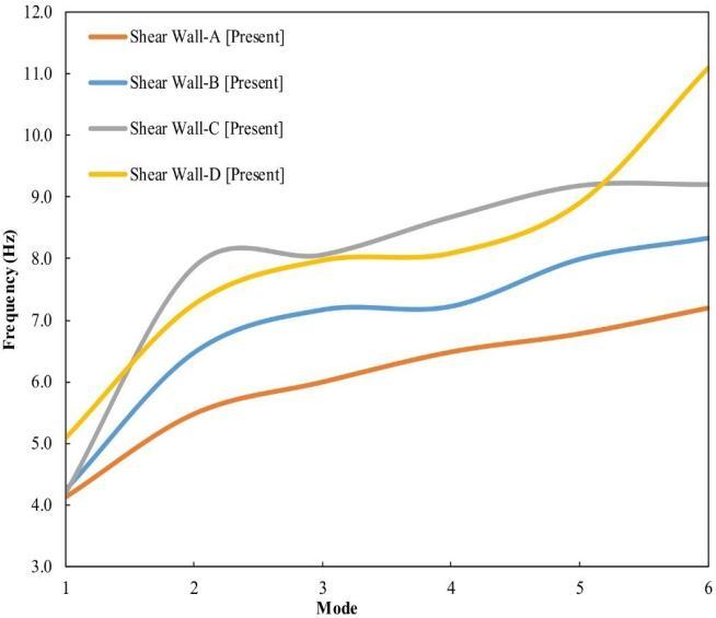
Table 4.1 Comparisonofmaximumdisplacementresults fordifferenttypeofstructure
Thickne ss of Plate
Shear Wall-A Shear Wall-B Shear Wall-C Shear Wall-D (mm) [Present] [Present] [Present] [Present]
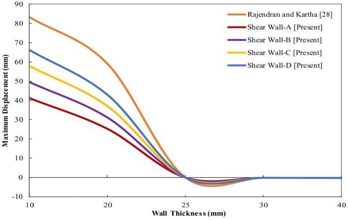
10 41.3037 49.6479 57.9921 66.3362 20 25.3038 31.218 37.1322 43.0464
25 0.0124 0.0149 0.0174 0.0199 30 -0.0768 -0.0878 -0.0989 -0.1099 40 -0.1074 -0.129 -0.1505 -0.1721
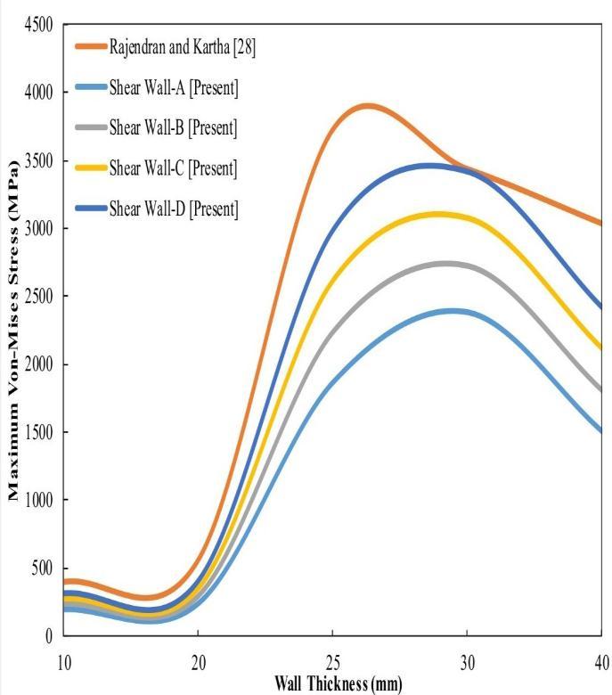
Table 4.3 Comparisonoffrequency(Hz)duetoseismic analysisfordifferentstructuretypewithsixmodes
Mode Shear Wall-A Shear Wall-B Shear Wall-C Shear Wall-D [Present] [Present] [Present] Present
1 4.13 4.25 4.19 5.09
2 5.48 6.47 7.87 7.26
3 5.99 7.17 8.07 7.97
4 6.48 7.22 8.68 8.09
5 6.77 7.98 9.19 8.90
Table 4.2 Comparisonofmaximumvon-misesstress resultsfordifferenttypeofstructure
Thickne ss of Plate Shear WallA Shear Wall-B Shear Wall-C Shear Wall-D (mm) [Present] Present Present Present
10 195.11 234.53 273.95 313.37 20 238.53 294.28 350.03 405.78
25 1866.48 2238.62 2610.76 2982.89 30 2384.79 2727.93 3071.07 3414.20 40 1508.60 1811.59 2114.58 2417.57
6 7.187 8.323 9.208 11.085
International Research Journal of Engineering and Technology (IRJET) e-ISSN: 2395-0056
Volume: 09 Issue: 10 | Oct 2022 www.irjet.net p-ISSN: 2395-0072
Analysisofalltypesofstructuresanddiscussionofallresults led to the following conclusions. A structure using earthquake-resistantwalls.
• From this work there is good agreement between the responsespectrumanalysisperformedtodeterminethesite shearwalleffectontheseismicbehaviorofthebuildingand thebehaviorofthestructure.
•Itisalsoconcludedthatsteelsilostructureswithincreased plate thickness also have reduced displacements from all structure types considered in this work, but from an economic point of view the cost increases with increased platethickness.Iwas.
•Inthisstudy,wealsofoundthatthefrequencygeneration of the structure was lower in Shear Wall A type for 6 differentmodes.
• For a 100 tonne capacity steel silo design, 10mm wall thickness and 3mm ring reinforcement, the design under consideration provides a significant increase in design stability,butShearwall-Adoesnotconformtothespecified type and literature. Provides more reliable performance comparedtoThemainadvantageofsteelsiloconstruction compared to concrete silo is that steel silo is cheaper comparedtoconcretesiloconstruction,solesstimeandcost comparedtoconcretesiloconstructionduetothedamage causedduringconstruction.canbere-installedwith
[1] SuvarnaDilipDeshmukhandRathodS.T,“Comparison ofDesign&SeismicBehaviourofRCCsilo”,International Journal of Science and Research, Vol.4, Issue 5, ISSN: 2319-7064,2015.
[2] Mateusz Sondej, PiotrIwicki, Jacek Tejchmannand MichałWójci,CriticalassessmentofEurocodeapproach to stability of metal cylindrical silos with corrugated wallsandverticalstiffeners,Thin-WalledStructures,Vol 95,no:335-346,2015.
[3] Marek Piekarczyk, Tomasz Michałowski, Dawid Kowalczyk,“Examplesofdesigningsteelshellstructures accordingtoeurocodes”,Technicaltransition,2015.
[4] Eutiquio Gallegoa, Angel Ruizb and Pedro J. Aguadob, “SimulationofsilofillinganddischargeusingANSYSand comparison with experimental data”, Computer and electronicsinagriculture,Elsevier,Vol118,pp.281-289, 2015.
[5] John W. Carson, “Limits of Silo Design Codes, Practice PeriodicalonStructuralDesignandConstruction”,ASCE, Vol.20,Issue2,2015.
[6] Krishna T. Kharjule1, Minakshi B. Jagtap, “Seismic AnalysisofR.C.C.andSteelSilo”InternationalJournalof ComputationalEngineeringResearch,Vol5,Issue7,pp 24-27,2015.
[7] M.WojcikandJ.Tejchma,Simulationofbucklingprocess ofcylindricalmetalsiloswithflatsheetscontainingbulk solids, Thin-Walled Structures, ELSEVIER, Vol 93, pp 122-136,2015.
[8] Manfred Bischoff, “Modelling of shell with the threedimensional finite element”, the sixth international conference on computation of shell and spatial; structure,2008.
[9] RamnathaDashandAnandRaju,“Bucklingbehaviorof compressive loaded composite cylindrical shell with reinforced cut outs”, “International journal of engineeringresearchandapplication”,vol2,Issue5,pp 2044-2048,2008.
[10] AdemDagungun,ZKaraca,ADurmus,“Causeofdamage andfailureinSilostructure”,Journalofperformanceof constructionfacilities,Vol23,Issue2,pp65-712009.
[11] Mueller.A,P.KnoedelandB.Koelle,“CriticalFillingLevels of Silos and Bunkers in Seismic Design” in 15WCEE, LISBOA,2012.
[12] HamdyH.AandAbdel-Rahim,“Responseofcylindrical wheat storage silo to seismic loading”, Journal of engineeringscience,pp2079-2102,2013.
[13] YangZhao,Qing-shuaiCao,LiangSunandLukaszSkotny, “Bucklingdesignoflargecircularsteelsilossubjectto windpressure”,Thin-WalledStructures,Vol73,no:337349, 2013 Ashwini Bindari and K.N.Vishwanath, “Analysis of Seismic and Wind effect on Steel Silo SupportingStructure”,InternationalJournalofResearch inAdventTechnology,Vol.2,No.9,2014.
[14] Dhanya Rajendran, “Comparison of lateral analysis of reinforcedconcreteandsteelsilo”,Internationaljournal of civil engineering and technology” Vol 5, pp 16-24, 2014.
[15] P.Iwicki,J.Tejchmann,andJ.Chróścielewski,“Dynamic FE simulations of buckling process in thin-walled cylindricalmetalsilos”,Thin-WalledStructures,Vol84, no:344-359,2014.
[16] Afzal Ansari, Kashif Armaghan and Sachin S.kulkarni, “Design and Optimization of RCC Silo”, International JournalforResearchinApplied
2022, IRJET | Impact Factor value: 7.529 | ISO 9001:2008 Certified Journal | Page421
International Research Journal of Engineering and Technology (IRJET) e-ISSN: 2395-0056
Volume: 09 Issue: 10 | Oct 2022 www.irjet.net p-ISSN: 2395-0072
[17] JMichaelRotter,“Localcollapseofaxiallycompressed pressurized thin steel cylinder”, Journal of structural engineering(ASCE),Vol116,No:7,1990.
[18] J.W Carson, R.T Jenkyn, “Load development and structural consideration in silos design”, Presented at reliableflowofparticularsolid,1993.
[19] Md.AlauddinandSobhrabuddinAhmad“Designforce and moment in circular silos based on Finite element analysis”,Journalofcivilengineeringdivision,VolCE23 No:1,1995.
[20] J.G.Teng,“Plasticbucklingapproximationfortransition ring beams in steel silos”, Journal of structural engineering(ASCE),Vol123(12):1622-1630,1997.
[21] James G. A. Croll, “Design Analysis of Tank and Silos”, Journal of structural engineering ,132(2), pp. 43-49, 2006.
2022, IRJET | Impact Factor value: 7.529 | ISO 9001:2008 Certified Journal |