International Research Journal of Engineering and Technology (IRJET) e-ISSN:2395-0056

Volume: 09 Issue: 10 | Oct 2022 www.irjet.net p-ISSN:2395-0072
AN OUTLINE OF HARMONICS AND MULTILEVEL INVERTER
2Mrs. Simardeep Kaur, 3Raina Jain
1PG, scholar, Dept. of Electrical and Electronics Engineering, SSGI, Bhilai, India.
2Assistant Professor, Dept. of Electrical and Electronics Engineering, SSGI, Bhilai, India.
3Assistant Professor, Dept. of Electrical and Electronics Engineering, CEC, Bilaspur, India. ***
Abstract- As conventional energy sources run out, several nations are turning to renewable energy sources like solar, wind, and BESS. Large-scale photovoltaic PV power plants have emerged as one of the key development trends in the PV industry in the field of renewable energy. Over the past two decades, there has been a notable increase in the production of and integration of solar power plants into the utility grid. The utilization of power electronic devices, such as DC/AC converters, has grown as the number of photovoltaic power plants has increased. Inverters are the name for this electrical power equipment. Inverters serve as a bridge between the grid and renewable energy sources by converting direct current into alternating current. Power plants that produce harmonics in the system use inverter-based technology and other non-linear loads. A lot of work has gone into developing ways for getting rid of or cutting down on harmonic distortions that this conversion's output causes. The purpose of this study is to look into the factors that contribute to harmonics in PV inverters, as well as their impacts and methods for reducing them.
Key words: Harmonics,Inverter,MultilevelInverter.
1. INTRODUCTION
The problem of grid harmonics isn't new. Utilities recognized the importance of harmonics within the Twenties and early Nineteen Thirties once distorted voltage and currentwaveformswerediscoveredontransmissionlines. Atthattime,thekeyconsiderationsweretheconsequences of harmonics on synchronous and induction machines, telephone interference,and power condenser failures. Results of a number of the first investigations are also reviewed by considering a typical 250-mile, 220-kV transmissionline:
1. Asending-quit emfofseven percentages 1/3harmonic incorporates fifty three percentage 1/3 harmonic on the receivingquitoftheroad.
2. Underfullload,the1/3harmoniconthequitoftheroad isdecreasedfromfiftythreeto29percentage.
3. Theenergycomponentonthegeneratoraspectis0.848 forawavecontainingharmonics(incomparisonwith0.96 foraharmonic-loosesinusoidalwave).
4. The energy component on the load aspect is 0.82 for a harmonic-loose sinusoidal waveform and is measured as 0.75throughmetering.
5. Foraninductionmotorconstructedin1930,harmonics triggered vibrations and periodic rasping sounds. Input energy measurements vary due to relative harmonic content. Rotor currents also are vary for numerous harmonic contents.
Suchbehavior,actualwithinsidethe1930s,canalsoadditionallyneverthelessexisttoday.Manufacturers' response to harmonics had been to construct gadget that tolerates greater harmonics andtolessenmutualcouplingtocellphone circuits.Nevertheless,it'sfarcleanthatharmonicsareoncemore turning into a extreme problem, representing for the primary time capability harm to purchaser hundreds in addition to the strengthnetwork.
TheIssueToday'scontrolframeworkconsonantissuescan befollowedtoanumberofvariables:
1. Thesignificantincrementof nonlinear loadscoming aboutfrommoderninnovationssuch as silicon-controlled rectifiers(SCRs),controltransistors,andchipcontrolsetc.
2.Arevisiontothegearplan'slogic.Thelower-below5Khzfrequencyrangeappearstobethemostharmfulfor controllingmachineryandgadgets.
Theseconditionsarenolongervalid,andutilitiesareincreasinglyconcernedaboutnoise.
2. EFFECTS OF HARMONICS ON THE POWER SYSTEM
For more than 50a long time, harmonicshave beendetailedto cause operational problems.A fewof the majorimpactsincorporate:
International Research Journal of Engineering and Technology (IRJET) e-ISSN:2395-0056
Volume: 09 Issue: 10 | Oct 2022 www.irjet.net p-ISSN:2395-0072
1. Capacitor bankdisappointmentfrom dielectric breakdown-orresponsivecontrolover-burden.
2.Obstructionswiththeswellcontrolandcontrollinecarrierframeworks,whichresultinthebreakdownofthemetering,stackcontrol,andfurtherexchangingstructures.
3.Intemperatemisfortunesin-andwarmingof-induction andsynchronousmachines.
4. Overvoltage’s andover the topstreamson the system' fromreverberationtoconsonantvoltages orstreamson the network.
5.Dielectric breakdown ofprotectscablescoming aboutfromconsonantovervoltagesonthesystem.
6 Frameworks for broadcast communications with inductiveimpedances.
7.MistakesininductionkWhmeters.
8.Flagobstructionsandtransferglitch,especiallyin solidstateandmicroprocessor-controlledframeworks
9.Impedanceswithexpansiveenginecontrollers and powerplantexcitationframeworks
10. Mechanicalmotionsofinductionand synchronous machines.
11.Unsteadyoperation ofterminatingcircuits based on zero voltagecrossingdiscoveryorlocking
Theseimpactsdepend,ofcourse,ontheconsonantsource, itsareaonthecontrolframework,andthearrangecharacteristicsthatadvancetheengenderingofharmonics.
2.1SourcesofHarmonicsHarmonic
Sourcesareseparatedintotwocategories:
1.Builtupandknown.
2.Modernandfuture.
2.2
EstablishedHarmonicsSources
'Asurveyof thewritingdemonstratesthat the known sourcesofharmonicsincorporate
1. Toothswellorswellswithin thevoltage waveform ofturningmachines.
2.Varietiesin air-gaphesitanceover synchronous machinepostpitch.
3. Fluxmutilationwithin thesynchronous machine from suddenloadchanges.
4. Nonsinusoidaldisseminationof the fluxwithin thediscusscreviceofsynchronousmachines.
5.Transformermagnetizingstreams.
6.Arrangenonlinearities from loads such as rectifiers, inverters, welders,bendheaters, voltage controllers,recurrenceconverters,etc.
2.3AnalysisofHarmonicsandTheirSources
Systemscontainingnonlinearcircuitparameterscarrynon sinusoidal streams indeed when the connected voltage is of a pure-sine waveform. Gadgets such as rectifiers and soaked transformers have been said as causes of circuit nonlinearitywhichcausevoltageandcur-rentsounds.The genuine wave shapes change considerably and depend on theloadsandthecontrolsources.Whethersingleorthreephase,oncethewaveshapeofboththecurrentandvoltage have been decided, the consonant substance can be analyzed. Examinations to determine the size and arrange of soundsarebasedonFouri-er'shypothesisandtheapplicationofQuickFourierChangesisthepremiseforadvanced investigationofinspectedinformation[1]
3. MULTILEVEL INVERTER
At first the inverters were utilized to drive for the most part the helping stack when the framework gets off. But, these days dueto expanded progression in innovation inverters improves their skyline of applications. In prior days as it were two level inverter were utilized and produces the yield with two distinctive voltage levels but it has tall exchanging misfortunes and consonant voltage causesthestreamoftheconsonantcurrentwithinthe circuit and produces the misfortunes. So, to overcome the impedimentscertainheadwaytakesputinexistinginvertersuchthatlevelscanbeexpandedmorethantwosothat unadulterated sinusoidal waveform is delivered at the output voltage and sounds within the yield can be smothered and rate of misfortunes can be diminished and this topologyisnamedasmultilevelinvertertopology.
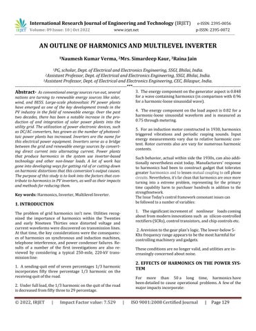
There are mainly three different types of the multilevel inverter
1)Diodeclampedmultilevelinverter.
International Research Journal of Engineering and Technology (IRJET) e-ISSN:2395-0056
Volume: 09 Issue: 10 | Oct 2022 www.irjet.net p-ISSN:2395-0072
2)Flyingcapacitormultilevelinverter.
3)CascadedH-bridgeinverter.
Overthese multilevel inverter hasa fewfocal pointsover thetwolevelinverter.
1)DiminishedConsonantimpactofdistortion.
2)Immaculatesine waveform due tonumerousvoltage levels.
3)Worksat bothessentialandtallexchangingrecurrencePWM
4)Diminishedexchangingmisfortunes
5)Tallcontrolquality
6)
Lowrateofalterofvoltage
Tragically multilevel inverter do have a few disadvantage one primary disadvantage of these it requires number of switches indeed in spite of the fact that they are of littler rating. Each switch is related to its door driving circuit sinceofthatgenerallyframeworkgetstobemorecomplex andexpensive.
4. CONCEPT OF MULTILEVEL INVERTER
Conventionaltwolevelinverterproducestwolevelswithin the yield voltage. Indeed in spite of the fact that the AC yield waveform is delivered it incorporates sounds and thesecausesthetallrateofalterofvoltageascomparedto the multilevel inverter. A few gadgets demands for low rateofalterinvoltage.
In multilevel inverter we create more than two voltages levelwhichshowsnearlyinoculatesinusoidalyieldvoltage wave-form.Whichhaslowdv/dt,lowconsonantdistortions sinceofnumerousvoltagelevelswithintheyieldthewaveform gets to be more smoother but with expanding levels thecircuitgetstobemorecomplexduetoexpansionofthe valves. And complicated control circuit is additionally required
4.1Comparisonbetweenconventionalandmultilevel inverter
S.no Conventional inverter Multilevel inverter
1. HigherTHDinyield voltage LowerTHDinyield voltage
2. Devicehashigh switchingstresses Devicehaslow switchingstresses
3. Notapplicablefor applicationhaving highvoltage
Applicableforapplicationhavinghigh voltage
4. Unabletoproduce highvoltagelevel Canproducehigh voltagelevel
5. Switchinglossesare high Switchinglossesare low
5. DIFFERENT TOPOLOGIES OF MULTILEVEL INVERTER.
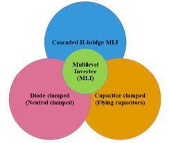
Figure1-Twolevelinverter
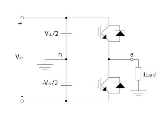
Figure-2Topologiesofmultilevelinverter
There areessentiallythreesortsof multilevel inverter classifiedagreeingto the voltage sourceutilizedwithin theinverter. The Fig.2underneathappearsthe topologies ofmultilevelinverter
International Research Journal of Engineering and Technology (IRJET) e-ISSN:2395-0056
Volume: 09 Issue: 10 | Oct 2022 www.irjet.net p-ISSN:2395-0072
5.1DiodeClampedMultilevelInverter
It was developed in 1981 and is also known as a neutral pointclampedinverter(NPC).TheDCMLItopology,which isutilisedtoproduceanoutputvoltagewiththreelevels,is shown in Figure 3. Four unidirectional power switches, two diodes, and two capacitors make up this topology's configuration. To distribute the blocking voltage among theclampingdiodes,theyarewiredinseries.
to different back-to-back topologies, such as adjustable speed drives and high voltage back-to-back connectivity. However, the issues with this converter include the challengeofbalancingandstabilisingthecapacitorDCvoltage in the DC link, as well as the difficulty in real power flow from a single inverter owing to discharging or overchargingoftheDClevelwithoutpropercontrol.
5.2FlyingCapacitorMultilevelInverter
.
Figure3-DiodeClampedMultilevelInverter
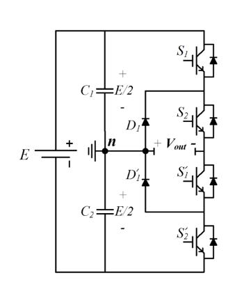
The output voltage in this architecture has three levels: Vdc/2,0,andVdc/2.Vdc/2 isproduced byleaving S1and S2switches on, whileVdc/2isproduced by turningon S3 andS4.The0levelvoltageiscreatedbyturningonswitches S2 and S3. It is anticipated that each active switching device will experience voltage stress throughout the passage of the equivalent voltage across the DC link capacitors, with this voltage stress being clamped to the voltage of each capacitor using diode clamping. In a practical application, the clamping diodes are connected in series to sharetheblockingvoltage.Then,eachactivedevicemerely needstoblockavoltagelevelofV/(m1)dc.Theclamping diodes' voltage ratings must differ for reverse voltage blocking. The primary problem with the design in high voltageapplications,whenusingtheDCMLIunderPWM,is the clamping diodes' diode reverse recovery. Due to its high-power delivery capability, simplicity, and efficiency, theDCMLIhasagreaterindustrialusethanthe othermultilevel converter topologies. It has found use in variable speedmotordrives,highvoltagesysteminterconnections, andstatic VAR compensators(SVC). The DCMLIconverter does not require a capacitor because all of its parts are connectedviaasingleDCbus.Asaresult,itcanbeapplied
The topologies of the FCMLI and DCMLI are very similar; the difference is that the FCMLI uses floating capacitors rather than clamping diodes. The size of the voltage steps in the output waveform of the FCMLI is a direct result of thevoltagevariationinthenearbycapacitors.The'm'level inverter's FCMLI structure consists of 0m 1 0 DC link capacitors. Figure 4 shows a schematic of the three-level FCMLItopology,whichalsoincludesaDCsupplywithtwo capacitors to acquire the voltage levels (Vdc/2, 0, and Vdc/2) and four unidirectional power switches and a flyingcapacitor.Forthepositivepolarityoutputvoltagetobe produced, switches S1 and S2 must be in the ON position, whilewhile S3 and S4 are switched ON for the negative polarity output voltage. Switches S1 and S3 or S2 and S4 are activated to produce the output voltage at the 0 level. Compared to a DCMLI, the voltage synthesis in the FCMLI is more adaptable. By carefully choosing the switching combination, the issue of voltage balancing can be solved when there are more than five levels. The ability to managethe reactiveandactive powerisoneofthistopology's main advantages. On the other hand, the usage of several capacitorsmakesthesystemexpensiveandchallengingto assemble. Furthermore, real power transmission in such setupssuffersfromlargeswitchingfrequencylosses.
Figure4-FlyingCapacitorMultilevelInverter
International Research Journal of Engineering and Technology (IRJET) e-ISSN:2395-0056
Volume: 09 Issue: 10 | Oct 2022 www.irjet.net p-ISSN:2395-0072
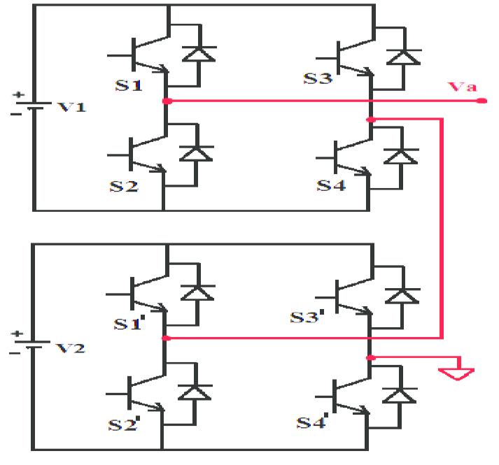
5.3CascadedH-BridgeInverter
The serial connecting of several single-phase H-bridge inverters with independent DC sources results in the creationofCHB-MLIs(SDCS).Figure3depictsanH-bridgewith fourunidirectionalpowerswitchesandoneDCsupply.The four switches (S1-S4) are connected in various ways to generate the desired output. Each inverter level is programmed to provide three voltage outputs (+Vdc, 0, and Vdc)viatheconnectionoftheDCsourcetotheACoutput. The +Vdc output is created when the S1 and S4 switches areintheONposition,whereastheVdcoutputisproduced whentheS2andS3switchesareintheONposition.Either S1andS2orS3andS4mustbeintheONstateinorderto generatethe0outputvoltage.Thefull-bridgeinverter'sAC outputsareconnectedinseriessuchthatthevoltagewaveform created represents the total of the outputs from all theinverters.Thenumberofoutputphasevoltagelevelsin acascadeinverterisdenotedbym=2s+1,wheresisthe varietyofDCsources.ComparedtoDCMLIandFCMLI,this design requires fewer components because clamping diodes and clamping capacitors are not used. Additionally, becauseitlacksDClink capacitors,itisfree ofthevoltage balancing issue. Conversely, independent renewable energysourcesandseparateconverterscanbeusedtoreplace the various DC sources, or by single renewable energy sources with multioutput converters where the voltage balancingisthemajorconcern.Multilevelcascadedinvertershavebeenproposedforuseinapplicationsforthegenerationofstaticvariables,aswellasaninterfacewithRES; theyhavealsobeenconsideredforuseinbattery-powered applications. A cascade inverter can be directly connected in series with the electrical system and utilised for static var correction as well. As they require independent DC sources when utilised in fuel cells and photovoltaics, they are appropriate for connecting RES to the AC grid. They havealsobeensuggestedforusageastheprimarytraction drive in electric vehicles because several batteries or ultracapacitors work as SDCSs in these applications. This topology's structure is adaptable and can be employed withvariousnumbersofinverterlevels.Byapplyingvarying ratios of DC sources and minimising switching redundancycausedbyinnervoltagelevels,differentoutputvoltagescanbegenerated.Tolessentherequirementforindependent DC sources, transformer-dependent CHBMLIs have beencreated; they havea CHBMLI-likestructure but are distinguished by the serial connection of the output voltage of the isolation transformer.[2]Here, the proposed studyoutlinesthedesignandapplicationofanovel multilevel inverter method for a solar-powered board. Most often,twolevelcascadeinvertersareusedforvoltageconversion from DC to AC. In this study, a two-level inverter
was able to provide two distinct voltage levels or yields. Theyieldvoltagewaveformisroughlyintheshapeoftwo levels,thereforetheTHDofa2-levelinverterisn'tashigh, or unusually high. To limit and lower the THD value, an underused multilayer inverter is shown here with fewer switches.DifferentlevelsofDCvoltagesourcesareusedto synthesizethedesiredACvoltage.[3]
Twodifferenttypesofmultilevelinvertersweremodelled and implemented in hardware in this study. According to the results of the simulation, the proposed topology 2's THDRangehasaconsonantmutilationspectrumof5.51%.
Theproposedarchitecture1includesactualizedmulticarrier stage relocated PWM as well. The most hard scenario isthevoltageadjustmentproblemsatthesourceandstack sides. By utilising a hysteresis controller within the proposed topology, the capacitor voltage adjusting technique isdevelopedbasedonthirdconsonantbalancedinfusion1. The model that was additionally produced for both the plannedandactualresultswasalsoauthorized.[4]
The use of a seven-level cascade H-bridge MLI for a gridconnected PV framework based on a Phase Shift Pulse WidthModulation(PSPWM)methodwasdemonstrated in thispaper.Thesystem wassuccessful inprovidinga compelling interface between the network and divided sun basedboardsasDCsourcesbycontrollingthebatteryexecutionbasedonMPPTandanadvancedcontroltechnique.
International Research Journal of Engineering and Technology (IRJET) e-ISSN:2395-0056
Volume: 09 Issue: 10 | Oct 2022 www.irjet.net p-ISSN:2395-0072
The proportionate demonstration includes three boards associated in arrangement to constitute the actualized PV/batteryframeworkcoordinateswiththeH-bridgeMLI. By regulating battery performance, the DC transmission voltage is kept stable in the face of various disruptive factors. Additionally, compared to a standard inverter, the cascade H-bridge MLI execution appears to significantly reducenoise.ThismakestheInvertercapableofeliminatingatallsumofconsonant,withmooTHDvoltage.[5]
ThisstudyinvestigatestheoperationofaPVsystemwitha boostconverter,wheretheMPPTmethodandamulti-level invertertopologycontroltheexchange.Duetoitsabilityto providewaveformswithafarwiderconsonantrange,multilevel inverters are suitable for use in high voltage and high control applications. This study first discusses the designandconsiderationoftheP-VandI-Vcharacteristics ofthePVframework,afterwhichtheyieldisrelatedtothe boost converter. MPPT calculation with P and O sort is used for exchanging. Finally, this previous structure is connectedtoacascadedmultilevelinverterbasedonmultiple carriers. The elemental yield voltage is improved by the cascaded multilevel inverter technique, which also reducesconsonantmutilation.Toanswerthequestion,asingle stage, five level cascaded inverter is used. Effectively, thepondercanbestretchedtoanm-levelinverter.Consonant examination, measured THD, and yield voltages are contrastedandanalysedwithaDC-ACinverterinaneffort tovalidatetheframework'smainelements.[6]
When compared to other conventional topologies, the inverter in the suggested figure contains less switches. The switch diminishment causes a decrease in the starting amount fetched. From the reproduction, the THD value is determined,anditiscomparedtotheTHDvalueofamultilayer inverter with values from more recent times and after level sifting. This results in a decrease in THD value whenusingtheSpecificConsonantEndBeatWidthTweak Strategy.Here,THDisreducedbyusingclosed-circlePWM techniques. Utilizing LCL filtering condition will reduce it initiallyasyoulearnasoundsperiod.
6. RESULT
As conventional energy sources run out, several nations are turning to renewable energy sources like solar, wind etc. Large-scale photovoltaic PV power plants have emerged as one of the key development trends in the PV industry in the field of renewable energy. Inverters serve as a bridge between the grid and renewable energy sources by converting direct current into alternating current. In this paper detail of harmonic and multilevel in-
verter has been discussed and various latest techniques whichareusedintoday’sworld.
REFERENCES
1. P. S. Harmonics, "Power System Harmonics: An Overview," in IEEE Transactions on Power Apparatus and Systems, vol. PAS-102, no. 8, pp. 2455-2460, Aug. 1983,doi:10.1109/TPAS.1983.317745.
2. A. K. Koshti and M. N. Rao, "A brief review on multilevel inverter topologies," 2017 International Conference on Data Management, Analytics and Innovation (ICDMAI), 2017, pp. 187-193, doi: 10.1109/ICDMAI.2017.8073508.
3. Yadav, Sagar & Khadse, Chetan. (2019). Implementation of Multilevel Inverter for Harmonic Reduction in Solar PV Application. 665-669. 10.1109/ICICICT46008.2019.8993146.
4. R. Priya and R. Valli, "Advanced Multilevel Inverter Techniques for PV Applications with Reduced Switching Devices and THD with Voltage Balancing," 2019 IEEE International Conference on System, Computation, Automation andNetworking (ICSCAN),2019, pp. 1-7,doi:10.1109/ICSCAN.2019.8878702.
5. Hassan,Abdelwahab &Azmy,Ahmed& Yehia,Doaa & Gurgi, Zeina. (2018). Harmonic Reduction for GridConnected Photovoltaic System based on Multilevel Inverter. Australian Journal of Basic and Applied Sciences.12.135-145.10.22587/ajbas.2018.12.9.23.
6. R. Priya and R. Valli, "Advanced Multilevel Inverter Techniques for PV Applications with Reduced Switching Devices and THD with Voltage Balancing," 2019 IEEE International Conference on System, Computation, Automation andNetworking (ICSCAN),2019, pp. 1-7,doi:10.1109/ICSCAN.2019.8878702.
BIOGRAPHIES
Naumesh kumar verma is a student of Mtech (Power system) in electrical and electronics engineering of final year. He is perusing Mtech degree from Shri Shankaracharya Group of Institution affiliated with Chhattisgarh swami Vivekananda Technical University. His interest is in power system, artificial intelligence and renewableenergy.

International Research Journal of Engineering and Technology (IRJET) e-ISSN:2395-0056
Volume: 09 Issue: 10 | Oct 2022 www.irjet.net p-ISSN:2395-0072
Mrs. Simardeep Kaur received her M. Tech degree in Electrical Engineering from RGPV,Bhopal.Sheiscurrently pursuingPh.D. degreeinElectrical Engineering. Currently, she is faculty in SSTC, Bhilai. Herresearchinterestincludes distribution generation protection,distributedgeneration &MicroGrid.

Raina Jain has received her Bachelor of Engineering Degree in Electrical Engineering from lakhmi chand institute of technology, Bilaspur in 2017. Master’s Degree in Power System Engineering from SSTC, SSGI, Bhilai, in 2021 affiliated with Chhattisgarh Swami Vivekanand Technical University, Bhilai. She is currently working as an Assistant Professor at the Department of Electrical And Electronics Engineering, in Chouksey Engineering College, Bilaspur. Her area of interestisinpowersystem,artificialintelligence,controlsystem,andrenewableenergy.