International Research Journal of Engineering and Technology (IRJET) e-ISSN:2395-0056

Volume: 09 Issue: 10 | Oct 2022 www.irjet.net p-ISSN:2395-0072
International Research Journal of Engineering and Technology (IRJET) e-ISSN:2395-0056
Volume: 09 Issue: 10 | Oct 2022 www.irjet.net p-ISSN:2395-0072
1Assistant Professor, Department of Electrical Engineering, IET Ayodhya, U.P., INDIA
2Research Scholar, Department of Electrical Engineering, KNIT Sultanpur, U.P., INDIA 3Professor, Department of Electrical Engineering, KNIT Sultanpur, U.P., INDIA ****
Abstract - For India's renewable energy sector to grow sustainably, wind energy will be essential. The tip speed ratio needs to be kept at its ideal level in order for a wind turbine to obtainthe most power possible from its speed in range-cut in to rated. Maximum power point tracking refers to the entire procedure of reaching the maximum power, and this is known as the tip speed ratio control (MPPT). The two MPPT methods (i) the perturb and observe technique (P&O) and (ii) the particle swarm optimisation algorithm method (PSO) are presented in this research. Thealgorithm blockreceives the voltage and current from the dc side as input, and it outputs the duty ratio, which is sent to the dc-dc boost converter. Both constant and variable speed wind input the model's simulation and analysis are carried out using MATLAB (simulink). Using a permanent magnet synchronous generator (PMSG), a model of a variable-speed wind turbine is shown, along with suggested control strategies. The model displays the mechanical, electrical, and aerodynamic components of the wind turbine. Matlab/Simulink simulations have been run to validate themodelandsuggestedcontrolstrategies.
Keywords: Wind Turbine, Permanent Magnet Synchronous Generator, Maximum Power Point Tracking (MPPT), Perturb & Observe (P&O), Particle Swarm Optimization (PSO). Boost converter
The urgent need to replace fossil fuels due to their detrimentalenvironmentaleffects,suchaspollutionand the greenhouse effect, has increased in recent years, making renewable energy sources (RESs) an essential part of the answer. Because of its benefits to the environmentandtheeconomy,windenergyisoneofthe main RESs [1]. According to predictions, 20% of the world'senergywillcomefromwindpowerby2030[2].
Two distinct wind turbines (WT) are used in the wind energyconversionsystem(WECS)configurationand are available on the international market. Compared to a variable speed wind turbine, the fixed speed wind turbine(FSWT)isstraightforwardtoinstallandmanage (VSWT). The VSWT, however, offers the benefits of
improved energy collection, lower load transient load reduction, and total load reduction controllability [3]. In variable-speed WECSs, a variety of generator types are used, including permanent magnet synchro- nous generators (PMSGs), doubly fed induction generators, and squirrel cage induction generators (SCIGs) [4, 5, 6]. Researchers have expanded utilisation of PMSGs in variable speed WECSs due to high power density, high performance efficiency, and high reliability even though DFIGs with partial power converters is a strong commercial contender. Additionally, the wide operating speed range and lack of DC excitation increase the WECSs efficiency by 10% [8–10]. Researchers are now looking at multi-phase machines to lessen torque pulsationsandcurrentper phasefluctuationswhilealso enhancingfaulttolerantcapabilities(FTC)[11,12].
Although they are used in WECSs, the dual-three-phase machines[13]andthesiX-phasemachines[14]needfor sophisticated control systems and pricey converters. Five-phase PMSGs are being used in numerous applications, including small-scale WECSs and maritime turbines [15, 16]. To optimise the power generated by the wind and to complete essential tasks of utility grid integration, the five-phase PMSG is used in conjunction with an effective control system for wind power generating [17]. The 1.5 MW five-phase PMSG used in thevariable-speedWECSarrangementisintegratedwith the utility grid (UG) via a frequency converter. The machine side converter (MSC) and the grid side converteraretwocategoriesforthefrequencyconverter (GSC). In order to extract the best produced power at each different wind speed and inject the active power intotheUGwithunitypowerfactor(UPF),thefrequency converter applies the back-to-back converter (BTBC) throughtheDC-linkcapacitor[18].
To increase the amount of wind-generated electricity, a number of maximum power point tracking (MPPT) algorithms have been suggested [3,6]. They are often dividedintotwogroups:indirectpowercontrollers(IPC) anddirect powercontrollers(DPC).Several other MPPT algorithms, including the tip speed ratio (TSR), the optimaltorque(OT)[19],andthepowersignalfeed-back (PSF)[20],areimplementedbytheIPCcontrol.TheTSR
International Research Journal of Engineering and Technology (IRJET) e-ISSN:2395-0056
Volume: 09 Issue: 10 | Oct 2022 www.irjet.net p-ISSN:2395-0072
algorithm is a simple and effective way to control the generator speed under a variety of weather circumstances.
From above discussion this research prefers standalone mode for PMSG based wind energy conversion system. This paper deals with P&O and PSO techniques for maximum power point tracking. The remaining sections are followings: Section II deals with wind energy conversion system, Sections III equipped with MPPT techniques, Section IV elaborates the simulation results andSectionVdescribestheconclusionofresearchwork.
The equation for mechanical power of WT is expressed usingEq.(1)as, 3 1 (,) 2 mpw PACV (1)
c Ccccec 2 12 3456 3456
(3) ThetipspeedratioλoftheWTisexpressedusingEq.(4) as, t w R V
(2) Where, 2 110.035 0.081 i optimal
(b) λoptimal - β curve Figure2(a)-(b).Polynomialfitofmeasureddata. From Fig. 2(a) it can be observed that the optimal value of the λ varies with β for maximizing the value of Cp.Therefore,arelationshipisdevelopedbetweenβand λoptimal to track Cp to maximumvalueand isexpressedin Eq.(6)[22].
(4) where, Ωt is the rotor speed, R is the radius. The developed mechanical torque τm of the WT can be expressedas,
P
The mathematical model of a PMSG is developed in the direct-quadrature (d-q) reference frame. The modeling of the PMSG in state equation is expressed usingEq.(7)&(8)as,
International Research Journal of Engineering and Technology (IRJET) e-ISSN:2395-0056
Volume: 09 Issue: 10 | Oct 2022 www.irjet.net p-ISSN:2395-0072
where, Rs is the stator resistance, id and iq are the currents, Ld and Lq are the inductances of the generator alongthedandqaxis, Lls istheleakageinductanceofthe generator and ωe is the electrical rotating speed (rad/s) ofthegenerator[23].
The electromagnetic torque (Tem) of the PMSG is expressedusingtheEq.(9)as, 1.5(()) emdslsdqqf TpLLiii (9) Where, ψf isthepermanentmagneticflux.
The boost converter's main purpose is to raise the voltage. Fig. 3.1 depicts the boost converter's circuit configuration.
When the switch is closed, the source voltage charges the inductor, which then stores the energy. Although theinductorcurrentgrowsexponentiallyinthismode, we'll assume for the sake of simplicity that it charges anddischargesinalinearfashion[25].Sincethediode preventscurrentfromflowing,theloadcurrent,which is provided by the discharge of the capacitor, remains constant.
During the ON period of the switching element, the inductor's current starts to increase and it begins to store energy. It is said that the circuit is charging. The inductor'sreserveenergybeginsdrainingintotheload andthesupplywhileitisin theOFF position[24].The inductor time constant affects the output voltage level, which is greater than the input voltage level. The switching device's duty ratio and source side voltage arecomparedtodeterminetheloadsidevoltage.

TheoperationofBoostConvertercanbeclassifiedintwo modes:
Fig. 3.3
In mode II, the switch opens, short-circuiting the diode as a result. Through opposing polarities, the inductor's stored energy is released, which charges the capacitor [26].TheoutputvoltageistheresultofaddingVS andVL whiletheloadcurrentstaysconstant.
The two MPPT methods used in this project are(i)PerturbandObserveMethod
(ii)ParticleSwarmOptimization
Letusdiscussthemindetail.
International Research Journal of Engineering and Technology (IRJET) e-ISSN:2395-0056
Volume: 09 Issue: 10 | Oct 2022 www.irjet.net p-ISSN:2395-0072
BASED MPPT:
It monitors the power fluctuation and, in response, makes modifications to the relevant parameter, such as the duty cycle of the DC-DC converter to control the dc voltage or to regulate current to change the rotor speed and track the MPP. This approach is based on randomly perturbingcontrolvariablesintinystages,thenchoosing the next perturbation depending on how the power curve has changed as a result of the previous perturbation. Due to its simplicity and lack of a mechanical speed sensor or anemometer, the P&O techniqueisacommonlyusedMPPTalgorithm[27].
Subscriptk+1denotesthevalueatsucceedinginstant
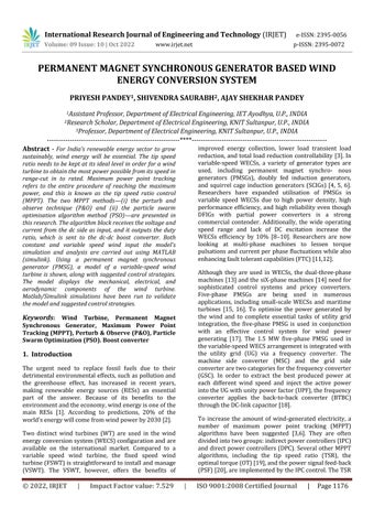
(ii) PARTICLE SWARM OPTIMIZATION (PSO) ALGORITHM BASED MPPT:
Due to its shown resilience, simplicity of usage, and potential for global exploration across a range of applications,PSOisanevolutionarycomputingapproach that is often used. It searches the optimised particle's position and velocity in an iterative procedure to discover a minimal value of the objective function in order to arrive at the best outcome. Along with a few learningandweightingcriteria,themethodmakesuseof parameters including swarm size (N), iteration number (T),andsearchspacedimension(D)[28]
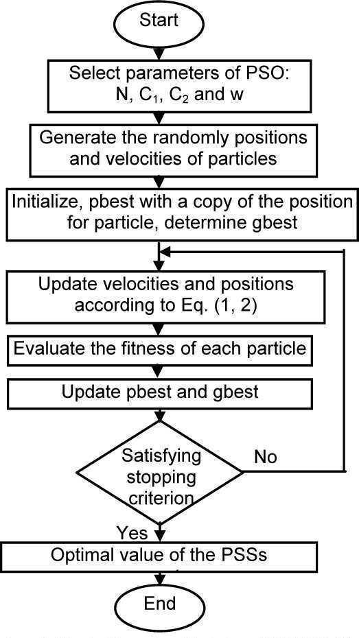
Fig. 3.4 P&O Flowchart
Where,D=dutycycle; I=Current; V=Voltage; P=Power;
Subscriptkdenotesthevalueataparticularinstant; Subscriptk-1denotesthevalueatpreviousinstant;
Fig. 3.5 PSO Flowchart
International Research Journal of Engineering and Technology (IRJET) e-ISSN:2395-0056
Volume: 09 Issue: 10 | Oct 2022 www.irjet.net p-ISSN:2395-0072
The above figure 3.2 shows the simple block diagram preferred for this research. As two MPPT methods have been used in the model, the block corresponding to the MPPT algorithm is altered to obtain the different MPPT control.
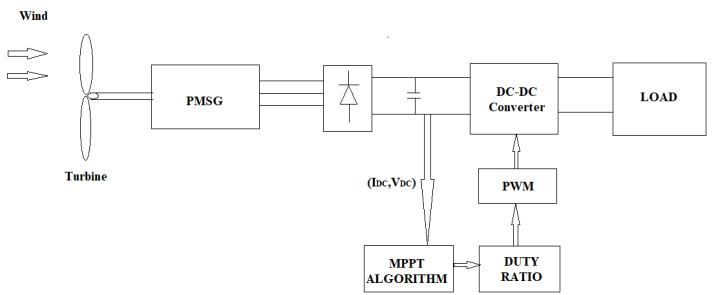
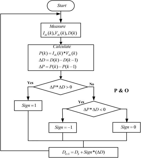
The MPPT block that I have used for the Perturb and Observe (P&O) method is purely a mathematical one. On the other hand the MPPT algorithm block used for PSO methodisaMATLABcompatiblePSOcode.
4.1 MPPT-1
4.1.1 PERTURB AND OBSERVE ALGORITHM BASED MPPT WITH CONSTANT WIND SPEED INPUT :
ThefollowingisthesimulationdesignedinSimulink: Theinputwindspeediskeptconstantat12m/s.
The following is the curve traced by dc power output of the System. As we can see initially the curve is traced upwardwhichsignifiesthattheMPPTisachieved.
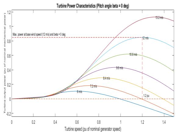
Fig 4.2 Resultofwindturbine
4.1.2 PERTURB AND OBSERVE ALGORITHM BASED MPPT WITH STAIRCASE INPUT WIND SPEED:
SIMULATION:-
The constant input in the previous simulation is removed bystaircaseinputinthissimulation.
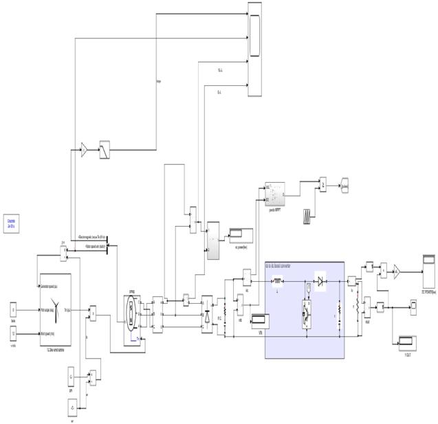
Fig 4.3 P&O MPPT Based WECS
Fig 4.1 Simulation Model
International Research Journal of Engineering and Technology (IRJET) e-ISSN:2395-0056 Volume: 09 Issue: 10 | Oct 2022 www.irjet.net p-ISSN:2395-0072
4.2 MPPT-2
4.2.1 PSO ALGORITHM BASED MPPT WITH STAIRCASE INPUT: SIMULATION:-
Fig 4.4 Result of DC o/p Voltage Component of PMSG : Name Value C 6.6094e^-04 D 0.8813 Io 30 Ioripple 0.2 L 4.5573e^-05 Po 12000 RL 13.33 Vinmin 50 Vout 400 Dl 48 Dv 2 Fs 20000 N 0.95 S.No. R load V in V out Pac Pdc 1. 13.5 55.87 281.33 7.163 5.863 2. 13.33 -0.17 0.00 0.4375 2.068e^20 3. 54 79.91 398.18 5.918 2.936 4. 56 4.77 0.00 0.4822 0
P L (W)
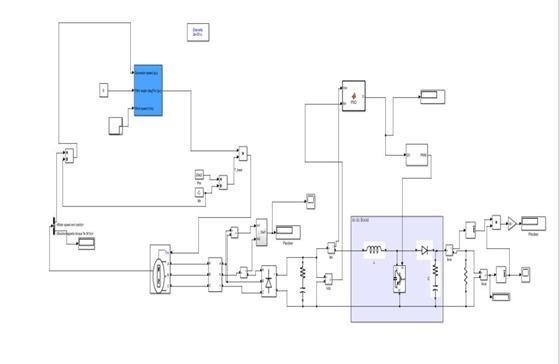
Fig 4.5 PSO MPPT Based WECS
6000
4000
2000
8000 Time(Sec)
0 0.5 1 1.5 2 2.5 3 0
Fig 4.6 Result of DC o/p Power

V. Conclusion
Both MPPT methods P&O and PSO have been successful in obtaining the maximum power. In all situations, MPPT is accomplished by adjusting the dc-dc boost converter's duty ratio. The Tip-speed ratio is influenced by the DC/DC control, which also impacts rotor speed. Thus, TSR is kept at a desirable level by regulatingthedutyratio.Wemaythusconcludethattipspeed ratio management has been effective. The WECS system has been designed using the necessary methodology. The simulation was carried out in MATLAB Simulink using both constant and variable
International Research Journal of Engineering and Technology (IRJET) e-ISSN:2395-0056
Volume: 09 Issue: 10 | Oct 2022 www.irjet.net p-ISSN:2395-0072
input conditions. PSO method has demonstrated superior performance than P&O algorithm because it takes less time to first obtain the MPPT under continuousinput.
Additionally, compared to P&O algorithm, PSO has exhibited superior steady state stability. We may also construct WECS in hardware to test its real viability as the simulation of WECS to regulate the TSR was performed in MATLAB Simulink. As was the project's goal, just the Tip-speed ratio is controlled here, but we canalsocreateanappropriatepitchcontrollerforWECS hardwareimplementation.
[1] Kaldellis J, Apostolou D. Life cycle energy and carbon footprint of offshore wind energy. Comparison with onshore counterpart. Renew Energy 2017;108:72–84.
[2] Hossain MM, Ali MH. Future research directions for thewind turbinegeneratorsystem. Renew Sustain Energy Rev 2015;49:481–9.
[3] Kumar D, Chatterjee K. A review of conventional and advanced MPPT algorithms for wind energy systems. Renew Sustain Energy Rev 2016;55:957–70.
[4] Zribi M, Alrifai M, Rayan M. Sliding mode control of a variable-speed wind energy conversion system using a squirrel cage induction generator. Energies 2017;10:604.
[5]SaeedMS,MohamedEE.Partitionedstatordoublyfedbrushlessreluctancemachine for wind generating systems. Power Systems Conference (MEPCON), 2017 NineteenthInternationalMiddleEast.2017.p.864–9.
[6] Tripathi S, Tiwari A, Singh D. Grid-integrated permanent magnet synchronous generator based windenergyconversionsystems:atechnologyreview. RenewSustain EnergyRev 2015;51:1288–305.
[7] Xie D, Lu Y, Sun J, Gu C. Small signal stability analysisfordifferenttypesofPMSGsconnected to the grid. Renew Energy 2017;106:149–64.
[8] Linus RM, Damodharan P. Maximum power point trackingmethodusingamodifiedperturbandobserve algorithm for grid connected wind energy conversion systems.IETRenew Power Gener 2015;9:682–9.
[9] Yang B, Yu T, Shu H, Zhang X, Qu K, Jiang L. Democratic joint operations algorithm for optimal power extraction of PMSG based wind energy
conversion system. Energy Convers Manage 2018;159:312–26.
[10] Bonfiglio A, Delfino F, Gonzalez-Longatt F, Procopio R. Steady-state assessments of PMSGs in wind generating units. Int J Electr Power Energy Syst 2017;90:87–93.
[11]Toliyat HA, Rahimian MM, Lipo T. dqmodeling of five phase synchronous re-luctance machines including third harmonic of air-gap MMF. Industry Applications Society Annual Meeting, 1991., Conference Record of the 1991 IEEE. 1991. p.231–7.
[12]Levi E, Bojoi R, Profumo F, Toliyat H, Williamson S. Multiphase induction motor drives–a technology status review. IET Electr Power Appl 2007;1:489–516.
[13] Reusser CA, Kouro S, Cardenas R. Dual threephase PMSG based wind energy conversion system using 9-switch dual converter. Energy Conversion Congress and EXposition (ECCE), 2015 IEEE. 2015. p. 1021–2.
[14] Abdelsalam I, Adam G, Holliday D, Williams B. Assessment of a wind energy con- version system based on a siX-phase permanent magnet synchronous generator with a twelve-pulse PWM current source converter. ECCE Asia Downunder (ECCE Asia), 2013 IEEE. 2013. p. 849–54.
[15] Liang C, Le Claire J-C, Aït-Ahmed M, Benkhoris M-F. Power control of 5-phase PMSG-diode rectifierinterleaved Boost set under health and fault modes. Electr Power Syst Res 2017;152:316–22.
[16] Youssef A-R, Sayed MA, Abdel-Wahab M. MPPT control technique for direct-drive five-phase pmsg wind turbines with wind speed estimation. Variations 2015;21:22.
[17] Rhaili S, Abbou A, Marhraoui S, El Hichami N. Vector control of five-phase Permanent Magnet Synchronous Generator based variable-speed wind turbine. Wireless Technologies, Embedded and Intelligent Systems (WITS), 2017 International Conference on. 2017. p. 1–6.
[18] Athari H, Niroomand M, Ataei M. Review and classification of control systems in grid-tied inverters. Renew Sustain Energy Rev 2017;72:1167–76.
[19] GanjefarS,GhassemiAA,AhmadiMM.Improving efficiencyoftwo-typemaximumpower point tracking
International Research Journal of Engineering and Technology (IRJET) e-ISSN:2395-0056 Volume: 09 Issue: 10 | Oct 2022 www.irjet.net p-ISSN:2395-0072
methods of tip-speed ratio and optimum torque in wind tur- bine system using a quantum neural network. Energy2014;67:444–53.
[20] Pagnini LC, Burlando M, Repetto MP. EXperimentalpower curveofsmall-size windturbines in turbulent urban environment. Appl Energy 2015;154:112–21.
[21]hul Pazhampilly,S.SaravananandN.RameshBabu, “Incremental Conductance BasedMPPT For PV System Using Boost and Sepic Converter”, ARPN Journal of Engineering and Applied Sciences, Vol. 10, No. 7, April 2015.
[22]Mei Shan Ngan and Chee Wei Tan, “A Study of Maximum Power Point TrackingAlgorithms for Standalone Photovoltaic System”, 2011 IEEE Applied Power ElectronicsColloqulum(IAPEC).
[23] Kok Soon Tey and Saad Mekhilef, “ Modified Incremental Conductance Algorithm for Photovoltaic System under Partial hading Conditions and Load Variations”, IEEE Transactions On Industrial Electronics, Vol.61,
[24] Luxy Xavier and Veena Wilson, “ Tracking of Maximum Power Point Using Direct Control Algorithm witha DC-DC Converterand a BLDCMotorforDomestic Applications”, International Journal of Engineering and Innovative Technology (IJEIT) Volume 4, Issue 10, April 2015.
[25]hul Pazhampilly,S.SaravananandN.RameshBabu, “Incremental Conductance BasedMPPT For renewable energy System Using Boost and Sepic Converter”, ARPN Journal of Engineering and Applied Sciences, Vol. 10, No. 7,April2015.
[26] Zhou Xuesong, Song Daichun, Ma Youjie, Cheng Deshu, “The Simulation and Design for MPPT of PV system based on Incremental Conductance method”, 2010 WASE International Conference on Information Engineering.
[27] Selmi T, Niby A, Devis L, Davis A. P&O MPPT implementation using MATLAB/Simulink. In Proceeding IEEE Conference on Ecological vehicles and Renewable Energies.Monte-Corlo;25-27March2014.p.1-4.
[28] Ye,M.,X.Wang,andY.Xu, Parameter extraction of solar cells using particle swarm optimization. Journal of AppliedPhysics,2009. 105(9):p.094502.
2022, IRJET | Impact Factor value: 7.529 | ISO 9001:2008 Certified Journal | Page1183