International Research Journal of Engineering and Technology (IRJET) e-ISSN: 2395-0056

Volume: 09 Issue: 10 | Oct 2022 www.irjet.net p-ISSN: 2395-0072
Design & Development of Prosthetic Leg
Abhishek Dixit1, Sumit Dhage2 , Mahesh Kavre3
Abstract - This article aims to design a prosthetic leg prototype that can be used by above knee amputees especially the people who cannot afford to invest in costly and expensive high-end prosthetics. This product can be used to sit, stand and walk comfortably without any backlash or jerk to the user. The size of the product is carefully designed to be an approximate replication of knee joint and has a relatively light weight as compared to its high-end counterparts. The knee mechanism is cast entirely from aluminum & the conical spring used is manufactured using spring steel. The knee joint mechanism has a cap and belt to be tied to the leg of the amputee using a belt and lower end of the knee is connected to the rod which connects the knee end to the ankle. The product is successfully tested and is modelled using Creo 4.0 and analyzed in Ansys Structural. Prosthetics manufacturing has reached great heights in technology and have achieved perfect muscular movement like a biological leg. But maximum people having leg disability cannot afford such high-tech technology for their leg. Our attempt is to achieve a similar movement of a leg at minimum cost and based on this attempt we are considering the manufacturing The lower middle-class people of the society find it difficult to purchase such prosthetic from private orthopedic centers so we have aimed to make it easier for those people to buy the product. Our low-cost project can also influence other producers to make such low-cost prosthesis and make them believe that it can be possible. This is not just beneficial for the producers but also to the consumers as it lowers the overall cost of such prosthesis due to aggressive competition.
Key Words: Amputees, Prosthetics, Creo 4.0, Prototype, AnsysStructural,Casting
1.INTRODUCTION
Prosthesisisanartificialdevicethatreplacesalostbodypart duetounfortunatetragedies,diseaseorduringchildbirth.If aprosthesisisutilizedforupperlimb,itisusuallyknownas upper extremity prothesis whereas if the prosthesis is targeted for hips and below it, then it is known as lower extremityprosthesis.
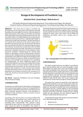
Accordingtothe research,thereisonehugeproblemthat still stood before all prosthetic users. Due to rapid rise of bio-technology and new age prosthetics, the price of prosthetics grew exponentially. Thus, making it nearly impossiblefor poorand low-classpeoplefrom even think about trying the option of prosthetics. The project is
specificallydesignedtotargettheIndianmarketasthereisa lackofalternativesinthispricesegment.Thus,insteadthe marketcouldbedivertedtoourproductwhichisspecifically targeted for those users who cannot opt for high end prosthetics and neither wish to use a wooden cane or crutches[1].
Fig -1: Demographics of Prosthetics Potential
2.METHODOLOGY
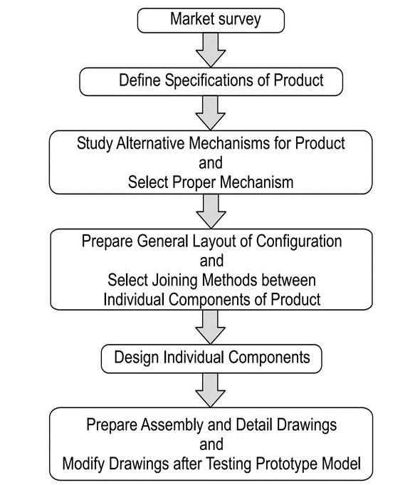
The Indian marketlacks thecost effective and efficient lower limb prosthetics that can reach the people in need. MostIndiansuse‘JaipurFoot’a low-costProsthetic maker that makes prosthetics from wood and is usually charges minimalamountwithnoprofitaspectandasapartofNGO. Butthisalternativeislesseffectivetouseasitcannotbeused in wet conditions and due to its low durability, it is not appropriate for prosthetics. The Jaipur Foot has no other outlets in India and the client has to go to Jaipur to get themselvesformeasurementandgetitscustomprosthetic.
Theprojecthasameanstoextendtherodtoadjustthe heightoftheprostheticaspertherequirementoftheuser. Thiseliminatestheneedofmakingprosthetic specifictoa singleuserandmakesitpossibletobemassmanufactured. The project also has a special addition to the preexisting prosthetics,duringsittingactiontheuserdoesnotrequire extension of the leg, so the knee mechanism has a locking system has gets activated once the required degrees of rotationisachievedbythekneejoint.[2]
Tomaximizethescopeoftheproject,certainprocedures werefollowedthroughtheproject:
1. MarketSurvey
2. Selectionofmechanism&material
International Research Journal of Engineering and Technology (IRJET) e-ISSN: 2395-0056
Volume: 09 Issue: 10 | Oct 2022 www.irjet.net p-ISSN: 2395-0072
3. Design&analysisofComponents
4. Assembly&Prototyping
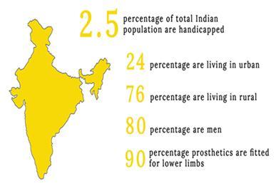
3.DESIGN PROCEDURE
The design procedure is illustrated using the following flowchart:
II. TimeRequired:
The usual waiting time after ordering of prosthetic productisusuallyhighbuttheoriginaltimerequiredmay varyaspertheorderedproduct.
III. Unavailability:
Theproductismanufacturedatlowrate,itisnoteasily availableforeverincreasingdemandsofthecustomers.
Fig.
-2: DesignProcedure
3.1 Market Survey
In India, out of 100 people facing disability 23 are sufferingwithTranfemoralamputation.Varioussolutions are present for such amputations. However, maximum peoplecannotaffordsuchexpensiveproducts.Myelectric prosthesis cost thousands of dollars and take weeks to manufacture. We aim to manufacture it at minimum cost. Duetoextensiveresearchinthefield,suchprostheticsare available at half the price of the imported ones that cost morethan1-2Lakhs.[3]
MajorProblemsFacedbyProstheticSolutions:
I. Cost:
Thepricerangeofhighendandcomplexprostheticrange from$3000(bioniclegs).
Fig. -3: ExistingSolutionsinIndia
3.2 Selection of Mechanism and Material
Accordingtotherequirements,aluminumisshortlistedasthe material for the knee mechanism due to its light weight & easy of manufacturing.MS Steel is selected as material for connectingrod.ThebeltasconnectorsismadeofVelcrocloth andplasticrespectively.Variousdifferentmechanismswere studied prior to prototyping[4], A few are mentioned as below:
1. Uniaxialspheroidaljointmechanism
2. Linkagemechanism
3 3 Design and Analysis of Components
Design criteria for various components were decided beforehand:
ForSpring:
The maximum load was 30N and the factor of safety was selectedas3.Springsteelwasselectedasthematerialforthe springwithayieldstrengthof1000N/mm2.
ForSpringSteel, Assumingwirediameter=2mm where,
UltimateTensileStrength=Sut, TensileYieldStrength=Syt, ShearYieldStrength=Ssy, ShearStress= τ
value:
International Research Journal of Engineering and Technology (IRJET) e-ISSN: 2395-0056
Volume: 09 Issue: 10 | Oct 2022 www.irjet.net p-ISSN: 2395-0072
Load=P, ModulusofRigidity=G Deflection=δ, No.OfCoils=n, For2mmwire, Sut=1420n/mm2 (Tensilestrength) Syt =0.75Sut =1065n/mm2 (Shearstrength) Ssy=614.5N/mm2 (τ)ShearStress(max)=Ssy/F.S AssumingF.S=3, τ=614.5/3
τ=204.835
CheckingactualStress, τs =8*w*c/Πd2
Whereload(w)=30N τs=8*30*10*/Π*22 =2400/Π*4 =190.98N/mm2
τs<204.835N/mm2
Springwireisacceptable D=C*d =10*2 D=20mm δ=8*30*202*n/G*d4 where, P=30N G=80*103N/mm2 δ=8*30*202*n/80*103*24 n=10*80*24*103/8*30*202 n=6.7 n~7
Solidlength=n*d =7*2 =14mm
Totalgap=(n-1)*2
Freelength=solidlength+totalgap+δ =14+(6*2)+10 =36mm
Pitch(p)=freelength/(n-1) =36/6 =6mm
ThedesignwasconductedwithreferencetoPSGdesigndata bookandthefollowingresultsweregained:
1. WireDiameter:2mm
2. CoilDiameter:10cm
3. Freelength:36cm
4. Pitch:6
Designofconnectingrod:
Itisassumedthattheloadisactinginaxialdirection,andthe rodwillundergostaticbuckling.
ThefollowingParametersaretakentodesigntherod:
Table -1: DesignParameters
Parameter Value
ColumnLength (L) 0.4m
Cross-sectionalarea (A) 736mm2
Secondmomentofinertia(I) 3250121cm4
Distancetotheneutralaxis(c) 50mm Eccentricity(e) 0 Designfactor(n) 5 Modulusofelasticity(E) 170GPa Yieldstrength(Sy) 165
Fig. -4 Simulation of Connecting Rod
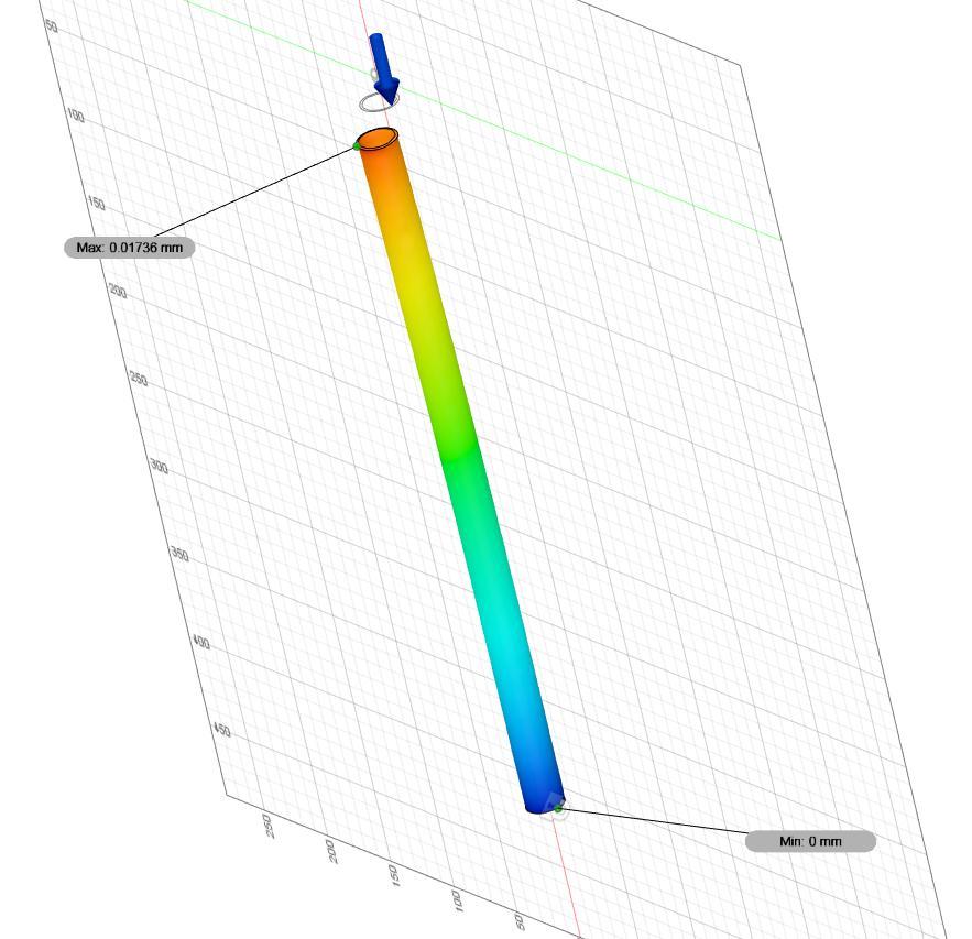
Table -2: DesignResult
Parameters Value
Effectivelengthconstant(C) 0.65
Radiusofgyrationofcolumn (r) 6645.24mm
Slendernessratioofcolumn (S) 0.06
Effectiveslenderness (Seff) 0.04
Criticalloadoffailure(Fc) 121436.99N
Allowableload(Fa) 24288N
2022, IRJET | Impact Factor value: 7.529 | ISO 9001:2008 Certified
International Research Journal of Engineering and Technology (IRJET) e-ISSN: 2395-0056
Volume: 09 Issue: 10 | Oct 2022 www.irjet.net p-ISSN: 2395-0072
ForKneeMechanism:
Usingpreliminarydesigncalculationsanddesignevaluation, materialwasselectedbasedonmaximumrigidityandlight weightappluication
Material:Aluminum6061
Table -3: Properties
Density 2.7E-06kg/mm3
Young’sModulus 68900MPa
Poisson’sRatio 0.33
YieldStrength 275MPa
Ultimatetensilestrength 310MPa
Thermalconductivity 0.167W/(mmC)
ThermalexpansionCoefficient 2.36E-05/C
Specificheat 897J/(kgC)
Thepropertiesofthematerialwereaddedintotheanalysisin theformofunputtothesoftware.Theloadsandconstraints are provided to the software along with the design parameters.
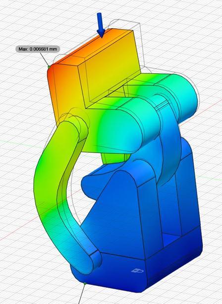
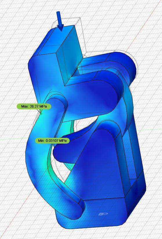
Thefollowingresultswereobtainedfromthesimulation:
Fig. -5: EquivalentStress
Fig. -6: TotalDeformation
The structural analysis shown in above figures were computedinAnsysStructuralSoftware.
Table -4: SimulationResults
Properties Minimum Maximum
Safetyfactor 5 7 Stress 0.31MPa 26.27MPa Displacement 0mm 6mm Reactionforce 0N 40.91N EquivalentStrain 4.502E 5.239E
4. MANUFACTURING
After design, the parts were fabricated as per the requirementsandwereassembledusingfasteners.Theknee mechanismwasentirelycastinafoundryusingafoammold, thespringwaspurchased,therodwasoperatedonlatheand threadedtofittheknee.Thecastcomponentswerefurther machinedusingCNCmachiningtomakeafitmoreaccurate. Oncethecomponentswerefittedaltogether,theassembly wastestedintheworkshoptocheckforworkingandcheck foranydefectsduringmanufacturing.
Oncetheprostheticwasstrappedontheamputee,userhad toprovideitwithaninitialhipflexiontoshift fromstance phasetowalkphase.Thepinthencompressedthespringas soon as the toe of the prosthetic touched the floor and as soonastheheelwastouchedthespringbegantoexpandand releaseitsstoredenergytoprovidetherequiredassistance
International Research Journal of Engineering and Technology (IRJET) e-ISSN: 2395-0056
Volume: 09 Issue: 10 | Oct 2022 www.irjet.net p-ISSN: 2395-0072
to the amputee. Thus, the cycle continued as long as the amputeedidnotstopprovidingitwithaforwardmomentum
Therestrictingmotioncanbedoneinthefurthertwoways:
Eitherprovideaspringtyperestriction(extension spring)
Ormakeafootflexibleenoughtoaccommodatethe changesmadeasperthesurface.
Here, both the arrangements provide the same results. However,wedecidedtogowithaspringtyperestrictionas itwouldbehighlyefficientandalsoberigidenoughtotake theloadofthebody.
6.RESULTS AND DISCUSSION
6.1Material improvements:
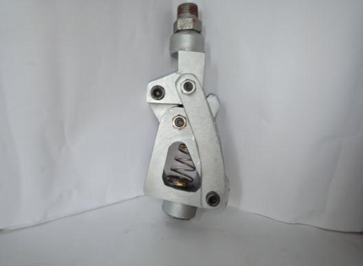
Fig. -7: Assembly of Mechanism
5.WORKING
Thespringactionactsagainsttheweightoftheloadofthe bodyandkeepstheleginstancephase.However,whenthe legshiftsintothemotionphase.Thelinearloadofthebody onlegbecomesmoreofanangularforce.Itactuatesthelever tocompressthespringandthusenablingthelegtobendand eventuallytowalk.Thenagainwhentheloadonthelegis lifted the spring comes back up and locks the leg into the stancephase.
The side brackets of the knee help the knee to bend at a specifieddegree.Withthislegtheuserisabletowalk,stand andevensitusingtheleg.Themovementhoweverislimited touserandalsorequiresalotofpracticetobeabletowalk using a prosthetic leg. The lever mounted between the assembliesplaysacrucialroleinenablingtheswingphaseof the leg. The motion of the swing phase moves a leg in an oscillatorymotionaboutthepivot(knee).
TheProjectisanexcellentadaptationofthefour-barlinkage mechanism. However advanced Prosthesis even utilizes a moreadvancedsixbarlinkage.
Theankleisthesecondmechanismoftheleg.Theankleis made of a cross linkage of bars at a central pivot point. It allowstheFootoftheLegtomoveinaverticaldirection.The anklejointprovidesthemovementforthelegthatisrequired forittowalkonaninclinedsurface.Whenauseriswalking onadownwardslope.Theankleadjuststothesurfaceand tiltsinaplaneparalleltothesurface.Similarly,whenwalking onanuphillslopethefootadjuststoit.
Theanklejointprovidesamovementabouttheverticalaxis which is crucial for the swing phase. As without a motion acrossthevertical,thefootofthelegwouldhittotheuphill surfaceandtherewouldbenoproperfootingonthefloor. However,arestrictingforceisrequiredonthefootandankle. Sothatitwouldnotbetoomuchflexible.
The prototype model resulted in increased weight due to metal components used. The connecting rod between the knee and the foot was a cast iron rod and the whole assemblyofthekneewasmadebyaluminum.Morechances are that the material will begin to rust and its weight carryingcapacitywillalsodecrease.Thus,discussionswere doneandmaterialsweredecidedaccordingly.
I. Forthekneeassembly,carbonfibercanbeusedas it is light weight and has very high strength and durability.
II. For the connecting rod, Polyvinylchloride (PVC) pipesorrodofsuitablediametercanbeusedbased ontheweightwhichistobecarried.
6.2Alternate Fastening Methods:
Forconnectingthevariouspartsoftheknee,NutandBolts were.Thisincreasedthefrictionbetweenthepartsdueto the threads between the bolts and also generated some unstable movement between them. Also, couplings were used to join the socket and the knee; this increased the weightoftheleg.Thus,discussionsweredoneandvarious solutionswereinculcated.
I. FortheassemblyofthekneeCotterandPincanbe used as it creates less friction and is easy to assembleanddisassembletheparts.OrCirclipscan beusedforholdingthepin.
II. ForjoiningthesocketwiththekneeSleevenutor nutandboltswouldbethemosteffectivechoice.
6.3Improvement in machining methods:
Lostfoamcastingwasdonetocastthevariouspartsofthe knee.Since Polystyrene was used for making thepatterns poresandblowholesweregenerated.Asaresult,different machiningmethodswereusedforgettingafinishedsurface.
2022, IRJET | Impact Factor value: 7.529 | ISO 9001:2008 Certified Journal |
International Research Journal of Engineering and Technology (IRJET) e-ISSN: 2395-0056
Thus,insteadofUsingpolystyrenepatternsasinlostfoam casting molding, Wooden Patterns can be used to reduce errors.
6.4Prototype Testing:
After protypes were tested out, we identified that the predefined phases of GAIT were achieved with ease and comfort.Theuserhadnodifficultyinuseoftheproduct.The weightoftheprojectwasnotunbearabletotheuseryetthe userfeltthattherewasaslightunbalanceinthelegs.Dueto which the user was not quite able to coordinate its prostheticleg.However,thelegfeltusefultothetestersince, theuserhadonlyexperiencedawoodenprostheticandwas quitepleasedwiththeresultsobtained[7].
Cost, Passive Prosthetic Knee for Users With Transfemoral Amputation in India, ASME 2015 InternationalDesignEngineeringTechnicalConferences and Computers and Information in Engineering Conference
[4] Dewen Jin, Professor Ruihong Zhang, PhD, Rencheng Wang,PhD,AssociateProfessor,JichuanZang,Professor Rehabillition Engineering Center, ”Kinematic And Dynamic Performance Of Prosthetic Using Six Bar Mechanism’’, Department of Precision Instruments, Tsinghua University, Vol. 40, No. 1, Pages 39–48, January/February2003.
[5] HarsimranJeetSinghSidhu,DesignandFabricationof Prosthetic leg, A journal of composite theory, ISSN: 0731-6755
[6] V.Bhandari,“DesignofMachineElements”Vol.2,pp433500,McGrawHill,ISBN,2012.
[7] Elliot J. Rouse, Nathan, C. Villagary-Carski, Robert W Emerson,Hugh,M.Herr,“DesignandTestingofabionic Dancing Prosthesis”, Volume 60, issue 5, Page 1181 –1190,2013.
3. CONCLUSIONS
Inthispaperweconcludethattheprojectisasuccesswhich inherentlyalwaysproducesasmooth,evencomfortablegait motionwhereineachphaseisidenticalwitheachandevery user that tested the project. The spring action caused a significantrelieftotheuserinwhichapproximately5%of thebodyweightwasprovidedbythespring.Thisprojectcan providemeansincludedwithinthemechanism tositona chairwhereinthelockactivatesandprovidescomfortduring sittingastheuser.Theprototypehasbeendevelopedasper requirementsandspecifications.Thus,theaimofdeveloping a“EconomicalLowerExtremityProsthetics”isaccomplished successfully.
REFERENCES
[1] ClaireA.Donnelley,BS,CorinShirley,CPO,ErickaP.von Kaeppler, BS, Alexander Hetherington, CP, Patrick D. Albright, MD, Cost Analyses of Prosthetic Devices: A SystematicReview,ArchivesofPhysicalMedicineand Rehabilitation,ACRM1404-15
[2] C.Wermillion,JointMovementLimitingArrangementfor Prosthetic Legs, US Patent 3, 663, 967, 1972 - Google patents,May231972.
[3] V. N. Murthy Arelekatti, Amos G. Winter, Design of Mechanism and Preliminary Field Validation of Low-
[8] Rajput, S., Burde, H., Singh, U. S., Kajaria, H., & Bhagchandani,R.K,Optimizationofprostheticlegusing generativedesignandcompliantmechanism,material proceedings: Volume 46, Part 17, 2021, Pages 87088715
Volume: 09 Issue: 10 | Oct 2022 www.irjet.net p-ISSN: 2395-0072 © 2022, IRJET | Impact Factor value: 7.529 | ISO 9001:2008 Certified Journal | Page1065
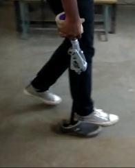
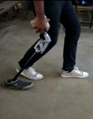
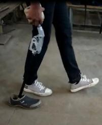
Fig. – 8 Phases of Motion