International Research Journal of Engineering and Technology (IRJET) e-ISSN:2395-0056

Volume: 09 Issue: 10 | Oct 2022 www.irjet.net p-ISSN:2395-0072
T-SPLIT DRIVE-TRAIN MODULE
1 , Soham Kulkarni2 , Atharva Kanetkar3 , Dr. Prof. N. G. Jaiswal4
1-3Department of Mechanical Engineering, PVG COET & GKPIOM, Pune 4Professor, Department of Mechanical Engineering, PVG COET & GKPIOM, Pune ***
Abstract - Operational and purposeful drive-train system of a vehicle should do the job of providing driving torque from power source and thus maintaining traction with surface. For effective torque distribution of torque at any road surface, torque vectoring concept is being analyzed, reviewed and tested. We solutions like ABS, Traction Control System, Electronic Stability Control, Limited Slip Differential, these aid vehicle to maintain stability, maneuverability, under-steer and over-steer reduction with respect to wheel spin correction etc. We have presented a framework consisting of mechanical, electric and electronic components, integrating conventional drive-train system, to escalate and efficiently provide torque distribution. Here, we have considered scenarios where torque vectoring is necessary, in support with analytical data to carry out simulations in MATLAB.
Key Words: Torquevectoring, electricdrive-train,servo motors,multi-plateclutchpack.
1.INTRODUCTION
In recent years, all-terrain vehicles (ATV) with hybrid or all electric power units are being accepted for personal, industrial and civil mobility catering private and public transportation, agricultural sector, security and defence, mining,constructionandforestryequipment.Challengeto design a drive-train with maximum surface traction, reduce wheel-spin. ATV (All Terrain Vehicles) with high end application such as extreme off road racing can be equipped to enhance driving capabilities of vehicle. The scope here is to increase overall efficiency and effective torque distribution of proposed system. While consideringconceptualrealmoftheproject,DFMandDFA canbefurtheranalyzed.
2. LITERATURE REVIEW
The Research Gate publications cited a conference paper, namely, Torque Vectoring Control for Progressive Cornering Performance in AWD Electric Vehicles. A real-time integrated Torque Vectoring Control function was designed and implemented in an AWD axle-split hybrid vehicle. The front axle had a conventional combustionengine,andtwoindividuallycontrolledelectric motors are located at the rear axle. The function aims to enhancethevehiclecornering performancebyyawtorque control allocation, at steady-state and transient steering
manoeuvre, with different propulsion inputs. Topics that were mainly discussed in this paper were Torque Vectoring, Vehicle Dynamics, Integrated Control, Electric Motors. The published conference paper helped us to get familiar with the concept of torque vectoring, understand performance of a hybrid two-door sports coupe car while corneringandselectingtherequiredelectricmotorforour drive-train.
IntheWorldElectricVehicleJournalVol.5,wecameacross a research paper namely, Torque Vectoring for Electric Vehicles with Individually Controlled Motors: State-ofthe-Art and Future Developments Thispaperdealswith the description of current and future vehicle technology related to yaw moment control, anti-lock braking and traction control through the employment of effective torque vectoring strategies for electric vehicles. This research paper gave us overview about behaviour of Torque vectoring for electric vehicle with individually controlled motor. The different conditions taking under conditions were, namely, 1) Torque vectoring control in steady-state conditions, 2) Torque vectoring control in transient conditions, 3) Torque vectoring control during emergency manoeuvre,4) Torque vectoringcontrol in offroadconditions.
A conference paper titled, A Torque Vectoring Strategy for Improving the Performance of a Rear Wheel Drive Electric Vehicle was published in Research Gate journal by authors Mr. Andrea Tonoli, Mr. Jyotishman Ghosh and Mr. N. Amiti. The conference paper presented a feedback controller for the torque vectoringcontrol of a rear wheel drive electric vehicle. The main objective of the work presented is to improve the vehicle maneuverability Distribution of driving/braking torque between left and rightwheelsallowsoptimalusageoftireforceswhichleads to better handling behaviour. The controller performance is evaluated by executing steady state and dynamic manoeuvre on a multi-body vehicle model. The dynamic manoeuvre include numerical simulations around a race track in order to understand the influence of torque vectoringacrossthecompleteworkingrangeofthetires.
In the 20th International Research/Expert Conference ”Trends in the Development of Machinery and Associated Technology” a research paper, namely, TORQUE VECTORING DIFFERENTIAL is published. A torque vectoring differential is presented in this paper. Torque vectoring function is achieved through an
© 2022, IRJET | Impact Factor value: 7.529 | ISO 9001:2008 Certified Journal | Page87
Udgar MeshramInternational Research Journal of Engineering and Technology (IRJET) e-ISSN:2395-0056
Volume: 09 Issue: 10 | Oct 2022 www.irjet.net p-ISSN:2395-0072
additional assemblycomprising ofthe differential gearset and motor. Since this solution does not use friction components it is efficient and durable. It has two main assemblies:standardopendifferentialwhichrealizesmain torque transfer and a torque vectoring assembly which consists of differential gear set with electric motor and provides(addsorsubtracts)additionaltorque
3. DESIGN BASED RESEARCH TOWARDS CONCEPT
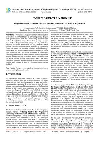
Proposed concept is based on an ATV prototype which is manufactured in-house for collegiate undergrad competitions as seen in photo. The shown vehicle is capabledrivinginheavyoffroad,roughcoursewithhighly strengthened tubular chassis which can take roll over impacts and maintain driver safety from intrusions and impact. The vehicle is capable of maneuverability as it is designed with independent double wishbone, direct actuated suspension system. The drive-train considered here is conventional rear wheel axle, whereon an open differentialdistributespowertoeachrightandleftwheels. Here highly articulable driveshafts with constant velocity joints(CV)transmittorquetodrivinghubs.
Controlarchitectureisdesignedwithreferencetoanalysis, speculation based on observation, driver feedback and experts’ advice vehicle with referring ‘TORQUE VECTORING DIFFERENTIAL’
Wherein, system performs well with an open differential as main torque distributing source; however it does not work atfullestondifferent surfaces.Maindrawbackofan open differential is that it distribute power to wheel with limited friction. For instance, vehicle is stuck at slippery clog where a wheel on ground surrounded with mud and otheroneisinair,ideallyinthesituationavailablepower should be sent to grounded wheel, but open differential worksexactlyoppositely.
To find out alternate systems or solutions to tackle the issue, similar systems with torque holding or torque vectoringmechanisms wereanalyzedsuchasLimitedSlip Diff (LSD), Anti-lock Braking System (ABS), Traction ControlUnit,etc.
The platform over which vehicle’s driving power is constrained is based on intercollegiate BAJA SAE India (Society of Automotive Engineers) competition. The rule for electric propulsion mentioned by SAE officials is presented along with image of the vehicle from the Team Conquistador(PVGCollegeofEngineeringandTechnology, Pune),
4. DETAILED DESIGN BASED ON CALCULATION
Accordingtoconstraintsset,inputandoutputparameters, design of sub-assembly components are explained as follows,
1.PowerSupplyUnit
Theelectricmotoractsasanautomatictransmissionalong with planetary gear set eliminating conventional synchronous-mesh gearbox. Our model’s architecture based on limited sourced EV power-train, we had our mechanical output to 6kw (or equivalent 10 hp). For reference, electric motor IPM 200-33-AW01 from Dana TM4whichhaspeakpowercapacityof6kwwith30Nmof peak torque at 3200 RPM. Capacity and type of chosen electric motor can be altered after prototype analysis and requirement.
2.FinalDriveRatio
Final drive ratio was calculated for buggy so as to climb 35% gradeability and drive with load of 1T. Final drive ratio of 1:12.6 was selected. Please refer to mentioned paper [2. SAEBAJA Drive-trainReport]fordetailedreport on consideration of drive ratios (along with associated competitionrules,assumptionsandprofessionalreviews).
3.DifferentialGearbox
Standard open bevel geared differential with gear ratio of 4.2 is used. Power is divided on each side of the outputof the differential. Therefore output torque from the differentialis63Nm.
Planetary gear system will provide 63* 3= 189 Nm where output gear ratio of planetary set. This means torque is equallysplitbetweenrightandlefttires.
International Research Journal of Engineering and Technology (IRJET) e-ISSN:2395-0056
Volume: 09 Issue: 10 | Oct 2022 www.irjet.net p-ISSN:2395-0072
According to design, as per requirement, when balance happenstobeataround25%and75%forinnerandouter wheels respectively, then 75% torque would be, 63*3*2*0.75=283.5Nmforouterwheel63*3*2*0.25=94.5 Nmforinnerwheel.
4.PlanetaryGearbox
Accordingtorequiredtorqueatwheels(570Nm),thefinal driveratioateachwheelwillbe570/2=285.
SoGearratiooftheplanetarygearboxis285/60=4.75.
??.ClutchPackUnit
Amultiplateclutchiscomposedofaseriesoffrictiondiscs that are connected to a shaft. The friction discs have frictionsurfacestoincreasethecoefficientoffriction.
Requiredclampingforceonclutchpackisgivenasfollows3.14*Pa*d*(D-d)/2[Referredfrom7. V.BBhandari]
Whereouterdiameteroffrictionsurface,D=120mmInner diameteroffrictionsurface,d=D*0.577(standardequation formultiplatedryclutch)
PressureCapacityforgraphitematerial,Pa=500MPa.
Max torque transmitted to one side of drive train, Mt= 283.5..300Nm(AssumingSafetyFactor)
ClampingForce,F=2760.377N
No. of friction surfaces, z=4Mt/(mu*F*(Dd) =11.45 …12 numberoffrictionsurfaces.
?? ActuationUnit
The clutch actuation system (mechanism) is the interface betweentheinputshaftfromplanetarysetandtheshafton clutch basket further connecting to driveshaft unit, which allows the control engagement and disengagement of the clutch.
??.ActuationDriveAssembly
An electric servo motor provides torque to an gear arrangement wherein, force is applied on actuation assembly to carry out clutch engagement(full, semi and auto)anddisengagement.Poweristransferredfromservo motors through a single stage constant mesh gearbox which acts as an torque multiplier providing sufficient clamping force for effective clutch actuation (please refer to5thpointforclampingforcecalculation).
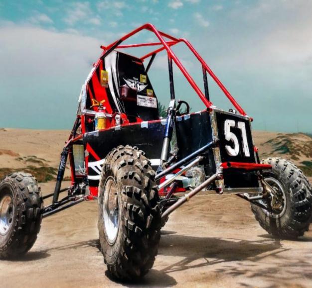
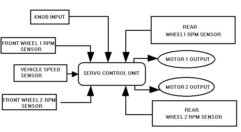
?? ServoControlModule
An algorithm has to be set up for control of servo motors [5*].Theseweredesignedonthebasisofvehicledynamics parametersexplainedfurther.
Factors such as weight transfer, relative tire slip, wheel RPM,yawandmomentplaycrucialpartthataffectstorque transfer at cornering situations. To get real time values of weight transfer, LVDT and strain gauge sensors can be used.
LVDT (Linear Variable Differential Transistors) are mounted on suspension struts to that vary resistance valueswithchangingstrutdisplacementwhileinoperation. Attachedsub-circuitssenddisplacementvalues(inmm)to controlunit.
Straingaugesmeasurestraincausedonvehiclebodydueto cornering,rollover,bumpintracketc.Thesecanbeusedin the system as alternative to LVDT or for calibration for switching betweenmanualandautomaticoperation.
Lastly,wheelspeedsensors(IR orhalleffect based)areto be usedto gettireslipratio.Ifone wheel spins more than others, possibly it has lost traction due to surface undulation (like mud, icy patch, dirt). In such condition, torquerequirementofthatwheel ismoreforextractionof vehicle.
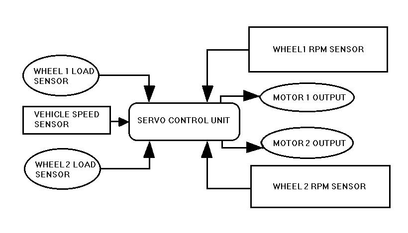
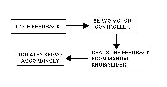
Followingareflowchartspresentingalgorithmstofollowed byservocontrolunitandcomponentsassociatedwithit.
I??AutoOperation
International Research Journal of Engineering and Technology (IRJET) e-ISSN:2395-0056
Volume: 09 Issue: 10 | Oct 2022 www.irjet.net p-ISSN:2395-0072
Iterating between modeling and simulation can improve the quality of the system design early, thereby reducing thenumberoferrorsfoundlaterinthedesignprocess.
Commonrepresentationsforsystemmodelsincludeblock diagrams, schematics, and state diagrams. Using these representations one can model mechatronic systems, control software, signal processing algorithms, and communications systems. A physical model was designed inMATLABSIMULINK.
Physical modelling helps to simulate the system which consists ofreal physical components.It employa physical network approach. SIMSCAPE components were used to design the Drive-train system. The system consists of a Traction Motor, Open Differential, Planetary Gear, Clutch packandWheels.
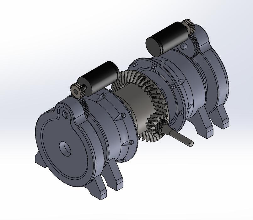
5. COMPUTER AIDED DESIGN
Design on Solidworks package was carried out for presentationpurposes.
SIMSCAPE diagrams mimic the physical system layout. If physical components can be connected, their models can be connected, too. The Physical Network approach, with its Through and Across variables and non-directional physical connections, automatically resolves all the traditional issues with variables, directionality and so on. An energy flow is characterized by its variables. Each energyflowisassociatedwithtwovariables,one‘through’ and one ‘cross’.The number of connection ports for each element is determined by the number of energy flows it exchangeswithotherelementsinthesystem,anddepends onthelevelofidealization.
The model was simulated in various situation where the friction coefficient, vehicle speed, cornering radius, road gradientetcwasvariable.
To vary the torque, Servo Motor was used to actuate the clutch,anddatawascollectedsuchasservoactuationtime, torque on each wheel, load transfer, wheel speed etc. A Servo Motor Controller was designed to reduce the actuation time of Servo Motor. It is designed to actuate according to the load, wheel slip, slip ratio, angular velocityandlinearvelocityofthevehicle.
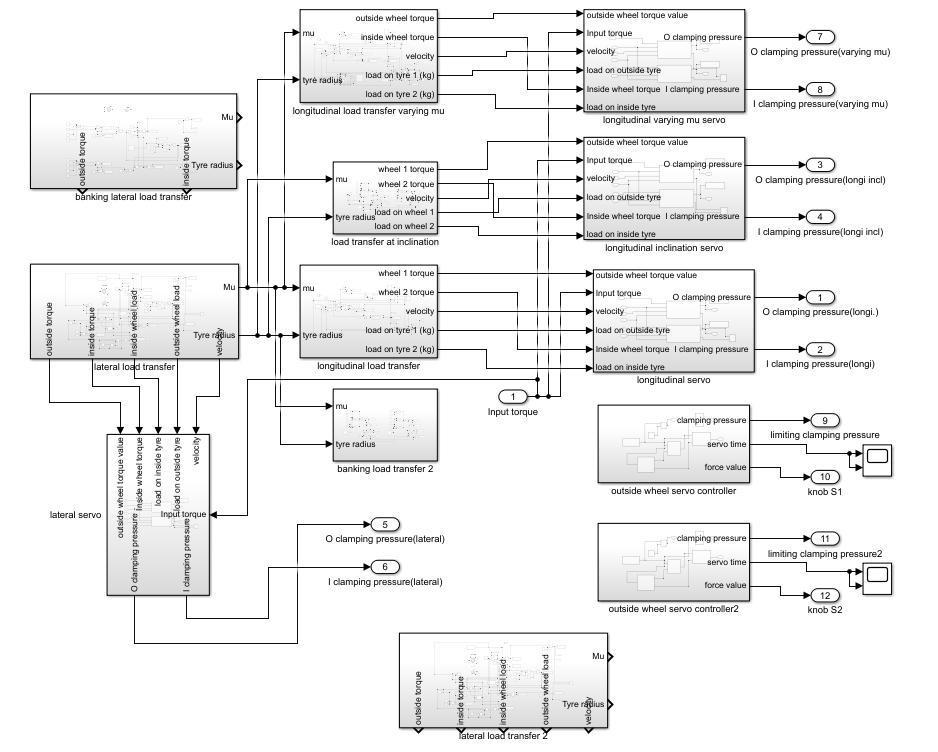
Thus improving the traction. It was necessary to reduce actuatetimetomakethesystemmorerobustandreliable. The Servo Motor Controller collects all the data from the vehicle and calculates how much the clutch needs to transfer torque. Complete schematic architecture of MATLABmodelisshownbelow.
6. VALIDATION PRIOR PROCESSING
Designmodelingandsimulationareespeciallyvaluablefor testingconditionsthatmightbedifficulttoreproducewith hardware prototypes alone, especially in the early phase ofthedesignprocesswhenhardwaremaynotbeavailable.
International Research Journal of Engineering and Technology (IRJET) e-ISSN:2395-0056
Volume: 09 Issue: 10 | Oct 2022 www.irjet.net p-ISSN:2395-0072
SchematicDiagramofCompleteUnit
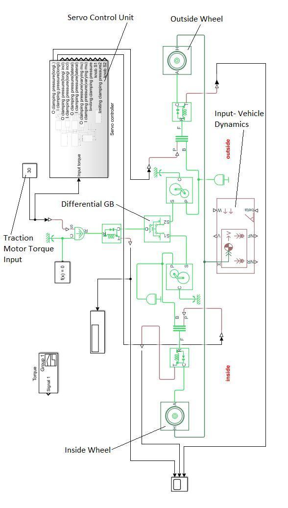
SchematicDiagramofServoControlUnit
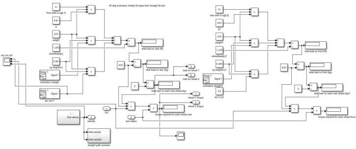
1.Scenario1-Loadtransfer
atInclination
Whenvehicleisdrivenona 40degreeslope.At endofthe slope, vehicle is driven continuously in straight line motion till end of the road. Scenario block-set shown below
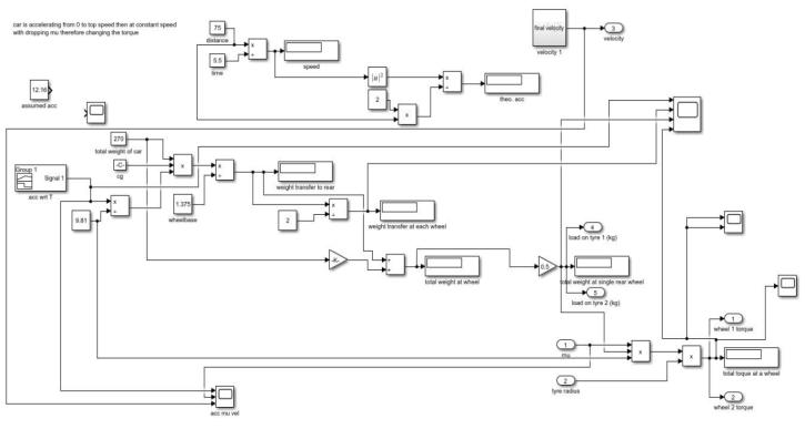
2.Scenario2-LongitudinalLoadTransfer
Vehiclewhenacceleratesfromresttoitstopspeed,caseis considered.Further,itcontinuesattopspeed, wherethee torque requirement for that instance is reduced. Scenario block-setshownbelow
International Research Journal of Engineering and Technology (IRJET) e-ISSN:2395-0056
Volume: 09 Issue: 10 | Oct 2022 www.irjet.net p-ISSN:2395-0072
7. VALIDATION RESULTS
The results were formulated according to cases considered in above section. Individual scopes are explained, which states varying speed, torque requirements and coefficient of friction in tires respectively in theoretical cases. These cases are formulated on proposed drive train block set. The data obtained by both systems is presented according to each scenario.
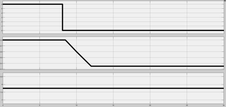
I)InclinedMotionScenario
Thebuggyisinitiallyatthestartofinclination.Thevehicle accelerates constantly till the inclination ends and then runsat thefinal speedtill the endofsimulation.After the inclination, the mu changes and remains constant till the end of simulation. Scopes for required torque, obtained torque, acceleration- velocity with changing mu and time takenforservo[Fig.61]areshownbelowrespectively.
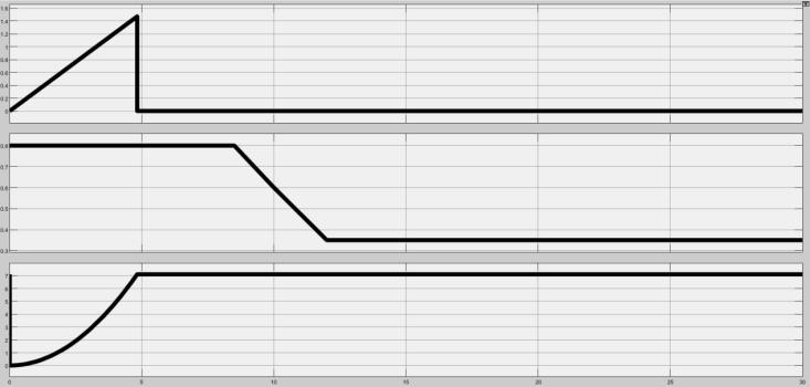
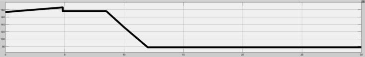
II)Circular Motion Scenario (For Longitudinal Load Transfer)
Thebuggyismovingataconstantlateralaccelerationona skid-pad.Afteralapthevehiclegoesstraighttilltheendof simulation with highest corner exit speed. Scopes for required torque [Fig. 62], obtained torque [Fig. 63] and accl velocity with changing mu [Fig. 64] are shown below respectively
Scope: required Torque curve of rear wheel1 and rear wheel2.Since equal loadis transferred atrear, the torque curveissameforbothwheels
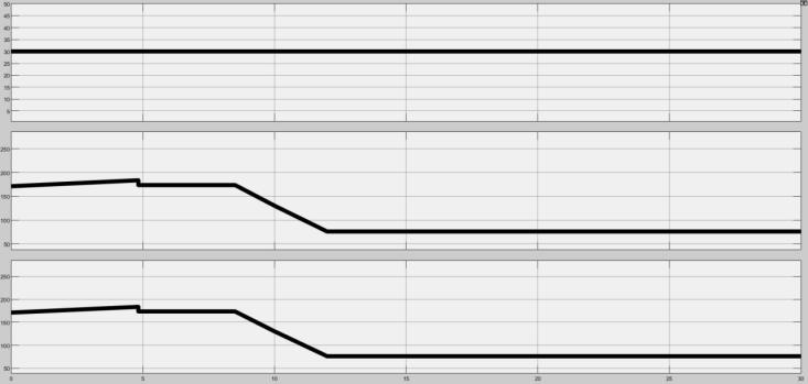
Scope: required Torque curve of rear inside wheel and rear outside wheel [window 1: inside wheel, window 2: outsidewheel]
Scope: Obtained Torque curve at wheel 1 and wheel 2 [window 1: input torque, window 2: wheel 1 torque, window3:wheel2torque]

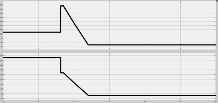
Scope:obtainedtorquecurveofrearinsidewheelandrear outsidewheel[window1:inputtorque,window2:outside wheel,window3:insidewheel]
Scope: window 1window2 window3showsacceleration mu&velocityrespectively
Scope: window 1window2 window3showsacceleration mu&velocityrespectively
8. CONCLUSION
The results obtained from the physical model have minimalerrorsasthemodelusesallrealtimeparameters.
International Research Journal of Engineering and Technology (IRJET) e-ISSN:2395-0056
Volume: 09 Issue: 10 | Oct 2022 www.irjet.net p-ISSN:2395-0072
Astherearevarioustypesoflosses(thermal,slip,meshing lossesorbacklashetc)intheclutch,gearsandshaft,there isadropinthedesiredandactualtorquevalues.
Duetotherisetimeinholdingtorqueoftheservo,thereis alagintime,whichdelaystheactuationofclutch.
Taking a dive into comparison made earlier with similar systemssuchasLSD,ABS,TractionControl(TCS),ESCetc, the proposed system can be presented as an optimum solution to problems encountered for extremely tractive, greatly handled and efficient automobile drive for AT vehiclesector.
ACKNOWLEDGEMENT
Completing the project and guiding through publishing would not have been possible without the support and guidance of Prof. Dr. N. G. Jaiswal (Professor, Department of Mechanical Engineering, PVG COET, Pune). We would like to extend our sincere thanks to Dr. M. M. Bhoomkar (Head of the Department of Mechanical Engineering, PVG COET,Pune) to department ofmechanical engineeringfor providing resources required.We would like to thank Team Conquistador, members , heads and guides for providingthenecessaryinformationandresourcesforthis project.Our thanks and appreciations also go to our colleague in developing the project. Thank you to all the peoplewhohaveguideduswiththeirwill
REFERENCES
[??] SAEBAJARuleBook2022 https://bajasaeindia.org/resource
[??] SAEBAJAReferencePaper https://www.ceias.nau.edu/capstone/projects/ME/2015/ SAE-MiniBaja/drivetrain/drivetrain_project_proposal.pdf
[??] SAEBAJADrive-trainPaper https://www.academia.edu/23709427/Design_of_a_Drive train_for_Sae_Baja_Racing_Off_Road_Vehicle
[??] ‘Torque Vectoring Control for Progressive Cornering Performance in AWD Electric Vehicles’ by Derong Yang , Martin Idegren , Mats Jonasson Volvo Cars Corporation,DepartmentofActiveSafetyandVehicle Dynamics, Gothenburg, SE-405 31, SWEDEN. The Royal Institute of Technology (KTH), Vehicle Dynamics, Department of Aeronautical and Vehicle Engineering,Stockholm,SE-10044,SWEDEN.
[??] EVS26, Los Angeles, California, May 6-9, 2012, ‘Torque Vectoring for Electric Vehicles with Individually Controlled Motors- State-of-the-Art and FutureDevelopments’byLeonardoDeNovellis,Aldo
Sorniotti , Patrick Gruber , Leo Shead , Valentin Ivanov,KristianHoepping
[??] A Torque Vectoring Strategy for Improving the PerformanceofaRearWheelDriveElectricVehicle
[??] ”Trends in the Development of Machinery and Associated Technology” a research paper, namely, TORQUEVECTORINGDIFFERENTIAL
[??] Bhandari.VB;‘DesignofMachineElements’
[??] Newton.K,Steeds.W;‘TheMotorVehicle’
2022, IRJET | Impact Factor value: 7.529 | ISO 9001:2008 Certified Journal