International Research Journal of Engineering and Technology (IRJET) e-ISSN: 2395-0056

Volume: 09 Issue: 10 | Oct 2022 www.irjet.net p-ISSN: 2395-0072
International Research Journal of Engineering and Technology (IRJET) e-ISSN: 2395-0056
Volume: 09 Issue: 10 | Oct 2022 www.irjet.net p-ISSN: 2395-0072
1Research Scholar at N.B. Navale Sinhgad College of Engineering, Solapur, Maharashtra, India-413255 2H.O.D. Civil Dept., N.B. Navale Sinhgad College of Engineering, Solapur, Maharashtra, India-413255 ***
Abstract - In the proposed study, the effect of soil structure interaction on gravity retaining wall has been examined using finite element analysis software ANSYS 18.0. The gravity retaining wall is completely resting on soil media and surrounded by soil media. The relevant amount of soil around and bottom of thegravity retaining wall has been modeled to simulate the in-situ conditions. The gravity retaining wall has been analyzed using static loading While analysing the gravity retaining wall, height and profile variation of gravity retaining wall has been carried out, which exhibited the response in terms of stress and deformation with significant difference.
Key Words: Gravity Retaining Wall, Soil Structure Interaction
Many problems in civil engineering involve some type of structural element in direct contact with the ground. Examples include building and bridge foundations; pavements and railway track systems, earth retaining structures; and underground conduits and tunnels. When forces are applied externally to the structural element and/orforcesdevelopedinternallywithintheground,both problemcomponents(structuralelementandground)must deformandmoveinacompatiblemanner.Thisisbecause neitherthestructural-elementdisplacementsnortheground displacementsareindependentofeachotherasaresultof their intimate physical contact. Therefore, these types of problems are broadly referred to as soil-structure interaction. Gravity Retaining Wall commonly used in variouscivilengineeringconstruction,bridges,roads,infra projectetc.Thecaseofdesignandconstructionpracticing engineer prefers gravity retaining wall. Normally, it is constructed with PCC for masonry. The Gravity Retaining Walldesignishailandprocesswhichisdrivenbystability criteria.Thebackfillsoildefinestheearthpressureactingon it.Alongthisparameter,ithascoupledeffectwithretaining wall. In this proposed study Gravity Retaining Wall is analysedusingFiniteElementMethodalongtheeffectofSoil StructureInteractionWhenforcesareappliedexternallyto thestructural elementand/orforces developed internally within the ground, both problem components (structural elementandground)mustdeformandmoveinacompatible manner. This is because neither the structural-element displacements nor the ground displacements are
independent of each other as a result of their intimate physical contact. Therefore, these types of problems are broadlyreferredtoassoil-structureinteraction.
The present research is aimed to study the effect of Soil Structure Interaction on Gravity Retaining Wall for economicalfeasiblecross-section.
AnattemptismadetooptimizethecrosssectionofGravity RetainingWallbyintroducingSoilStructureInteractionto thestructure.HeightvariationisconsideredforGRW.The maximumstressesinducedduetoSSIandwithoutSSIare analyzedandbythoseresultseconomicalcrosssectionarea isobtained.
Aretainingwallisanygeotechnicalstructurewhichisused toretainamassofsoilthatwouldotherwisetendtomove downslopeduetogravityandstressesactingwithinthesoil
The contribution has been done by the researchers to optimizethedesignofearthretainingstructuresandalsoin the direction to develop an earth retaining system using different innovative concepts. The researchers applied different optimization techniques and adopted a nonconventional system for different types of retaining walls like reinforced concrete structure wall, a gravity wall,etc. Theresearcherusedsoilstructureinteractionwithvarious structures, with various parameters, some of researchers contributed in cavity retaining wall & in soil structure interaction along with gravity retaining wall presented as follows,
Sunil Gupta, Tsung-Wu Lin, Joseph Penzien, ChanShioung Yeh [1] describedahybridmodelfortheanalysisof soil-structure interaction proposed which promises to be superiortothe19thtimemethodsofanalysis.Themodelling achievedbypartitioningthetotalsoil-structuresysteminto anearfieldandafarfieldwithhemisphericalinterface.The near field consists of the structure, which analyzed and a finite region of soil around it was modelled by the finite elementmethod.Forthesemi-infinitefarfield,impedance matrix corresponding to the interface degrees of freedom developed which accounts for the loss of energy due to wavestravellingawayfromthefoundation.
International Research Journal of Engineering and Technology (IRJET) e-ISSN: 2395-0056
Volume: 09 Issue: 10 | Oct 2022 www.irjet.net p-ISSN: 2395-0072
R. M. Ebeling [2] conductedtheinvestigationontheaccuracy oftheproceduresemployedintheconventionalequilibrium method of analysis of gravity earth-retaining structures foundedonrockusingfiniteelementmethodofanalysis.The results of load analyses showed when the loss of contact along the base of a wall modeled in the finite element analysis,thecalculatedvaluesofeffectivebasecontactarea andmaximumcontactpressurearesomewhatlargerthan those calculated using conventional equilibrium analyses. Thevaluesofthemobilizedbasefrictionanglecalculatedby bothmethodshadinpreciseagreement.
K. Pitilakis and A. Moutsakis[3] studiedasystematiccritical review of the different design methods gravity retaining walls using the case of the seismic behavior of Kalamata harbor quay wall during the large Kalamata’s earthquake (Ms=6.2,13.9.86).Intheirstudiestheyappliedtheclassical proceduresofaseismicdesignoftheGravityRetainingWalls basedonthe“limitedstrength”criterion(MononokeOkabe method), and the method based on the concept of “acceptance limited displacement” (Richards and Elms). They compared all the result with the existing measurements.Theyusethisresultfordesignconsideration forthegeneralreviewoftheaccuracyandlimitationofeach method.
Robert M. Ebeling [4] presentedareviewofpreviouswork inwhichthefiniteelementmethodwasusedtoanalyzethe soil-structureinteractionofearthretainingstructuressuch as U-frame locks, Gravity Retaining Walls, and basement walls.Thismethodofanalysisresultedinthecomputationof stresses and displacements for both thestructureandthe soil backfill. Applications of the procedure showed the importanceofmodelingtheactualconstructionprocessas closelyaspossibleandtheuseofanonlinearstress-strain soilmodel.Additionalrequirementsincludedmodelingthe interfacebetweenthesoilbackfillandthewall,whichused interfaceelements.Healsoincludedtworecentapplications of the finite element method for the analysis of earth retainingstructures,whichwasloadedsoheavilythatagap developed along the interface between the base of the structureanditsfoundation
Timothy D. Stark, Steven M. Fitzwilliam,Joseiph J.Vettel, Robert M. Ebeling [5] describedSoil-StructureInteraction ParametersforSilts.Theytriedtocharacterizethedrained and undrained stress-strain behavior of normally consolidated silts and clayey-silts. They used the result of their research to develop a database of hyperbolic stressstrainandMohr-Coulombstrengthparametersforsiltsand clayey-silts. They carried out extensive drained and undrainedtriaxletestsonsiltspecimenswithvaryingclay contents.Theyusedpercentagesofclayinthesiltmixtures were 0, 10, 30, and 50%. "The effect of density was investigated by compacting the triaxle test specimens at Standard Proctor relative compactions of 85, 90, 95, and 100%. They summarize the test results and the resulted
hyperbolic stress-strain and Mohr-Coulomb strength parametersforthevarioussiltmixturesconsidered.
T. Kupsmy, Mark A. Zarco [6] describedthefiniteelement computer program SOILSTRUCT used in the evaluation of soilstructureinteractionofearthretainingstructure.
Mete Oner, William P. Dawkins [7] conducted a comprehensive analysis procedure to understand the soil structure interaction, mechanism involved in behavior of floodwall systems. They used finite element method with suitablemodelofthesoilstructureinterface,nonlinearsoil behavior,andloadingsequence.Ontestsection,theyusedan existedfloodwallforverificationofanalyticalmodel.
Ernesto Cascone, Agatino Simone Lo Grasso, Michele Maugeri [8] conductedsomeshakingtabletestsperformed onasmallprototypeofGravityRetainingWallretainingdry sand was described. Shaking table studies carried out in order to study the dynamic behavior of gravity retaining wallsrestingonrigidfoundationsoil.Twodifferentsystem had taken into consideration namely a wall retaining a horizontalbackfillonwhichuniformsurchargewereplaced andawallonwhichtheuniformsurchargewasplacedtoa distancetotheheadofthewall.
Kenji Watanabe, Yulman Munaf, Junichi Koseki, Masaru Tateyama, Kenichi Kojima [9] conductedaseriesofshake tabletestswithirregularexcitationonretainingwallmodel consistofsixdifferenttypes.Theystudiedthebehaviorsof severaltypesofmodelsretainingwallssubjectedtoirregular excitation.
WANG Jiachun [10] discussedinfluenceofseveraldifferent boundary conditions on analysis of SSI. In structural responseofearthquakes,theassumptioninthefoundation medium was stiff and the seismic motion applied at structuresupportpointsweresameasfree-fieldearthquake motion at that location means the SSI were neglected. Nevertheless, the effect was taken in to account when the structuresupportedonasoftsoil.Acomparisonofreactor buildings response as predicted by CLASSI and FLUSH showeddifferences.InanalysisofSSItheoutwardlyradiated energy,transmittingboundaryconditions weretakeninto consideration.
Dr. P. P. Tapkire [11] described Optimization of gravity retaining wall profile by introducing cavity. In which the main aim of this paper is to develop a cost effective and structurally efficient profile of gravity retaining wall by introducing cavity in the section. For this, various section sizesofgravityretainingwallareanalyzedandaccordingly profileisselectedandthenafterselectionofanappropriate profile of gravity retaining wall stability calculations are carried out for various heights using ‘C’ programming by strengthofmaterialapproach.
International Research Journal of Engineering and Technology (IRJET) e-ISSN: 2395-0056
Volume: 09 Issue: 10 | Oct 2022 www.irjet.net p-ISSN: 2395-0072
Ms. Patil Swapnal V. [12] described,EffectofSoilStructure InteractiononGravityDam.Theeffectongravitydamhad beenexaminedusingfiniteelementanalysissoftwareANSYS 14. The gravity dam completely resting on soil media and surrounded by soil media. The relevant amount of soil aroundandbottomofthegravitydamhadbeenmodeledto simulate the in-situ conditions. The gravity dam was analyzedusingdynamicloadingintransientanalysisusing Imperial Valley (1940) earthquake record was included. Analysisofthegravitydamcarriedoutandtheinfluenceof soilpropertiesstudiedattheregionoftransversesections, which exhibited the response in terms of stress and deformationwithsignificantdifference.
In a gravity retaining wall the force of the retained soil is heldbackbytheself-weightofthewall,withsomeassistance from shearing resistance and bond. Analysis of structure with soil structure interaction effect is done by Finite ElementMethod(FEM).
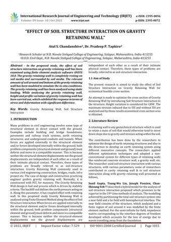
A gravity retaining wall with a vertical face retaining horizontal backfill is considered in this research work Backfillsoilhavingadensityof18kN/m3isconsideredalong with M25 grade of concrete for gravity retaining wall for analysis.Thecross-section ofGRWunderconsiderationis showninFigNo.1.Variationofdimensionswithrespectto their heights are analysed. In this research work, the response for modeling of GRW soil is formulated by discretizing the system into two substructures which are GRWsectionwithoutandwithSSI HereANSYS18.0isused fortheanalysisofthegravityretainingwallsection.
In the properties of Gravity retaining wall, geometry variables of retaining wall and material properties are mentioned. The geometry variables ofretaining wall are given in Table 1. Shape of retaining wall with geometry variables is shown in Fig. no. 1. Material properties of retainingwall[12] ,soilismentionedinTable2.
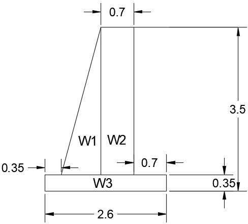
Fig. No. 1: Geometry variables of GRW
Table 1: Geometry parameters of GRW
TopWidth 0.7m Bottom Width 1.55m StemHeight 3.15m Foundation SlabDepth 0.35m SlabWidth 2.6m
GRW
Table 2: The material properties of GRW and Soil
Density 25kN/m3
GRW
Modulusofelasticity 31027MPa Poisson’sratio 0.2 soil Density 18kN/m3 Modulusofelasticity 2.62Mpa Poisson’sratio 0.4
ConsideredGRWc/sisobtainedbytrial-errorprocessusing stability condition for profile and heights For that excel spread sheets are prepared and cross-section of GRW is finalized.Finalizedcross-sectionofGravityRetainingWall are analysed using Finite Element package considered for profileanddifferentheightusingSSI
In this problem of GRW with and without soil structure interactionsystemisanalyzedusingsimplifiedanalysisof fundamentalresponseisvalidatedwithANSYSresults.
The stresses obtained by SOM approach calculation at differentloadofGRWarecomparedwithresultsobtainedby Anasys18.0
International Research Journal of Engineering and Technology (IRJET) e-ISSN: 2395-0056
Volume: 09 Issue: 10 | Oct 2022 www.irjet.net p-ISSN: 2395-0072
After comparing the results, it is observed that SOM approachandAnsys18.0resultsarepracticallysimilar.
Hence, the formulation which is adopted for the farther studytosolveGRW-soilinteractionandeffectforcalculating deformation,maximumstressandminimumstresses
ThecurrentresearchpaperisfocusedontheeffectofSSIon Gravity retaining wall as per mentioned in the previous section.Geometryofgravityretainingwallandparameter consideredforthefiniteelementanalysisofgravityretaining wallexercisedasdiscussed.
Gravityretainingwallwithdifferentgeometryandheights are designed which are governed by stability criteria, dimensionsofgravityretainingwallforvariousheightsare calculatedusingworksheetwhichseparatelydevelopedfor designofgravityretainingwallwithconsideringhorizontal backfill as a loading case. The various Heights with and withoutconsiderationofsoilstructureinteractionaresolved using finite element package. Maximum and minimum of deformation and maximum and minimum stresses are obtainedforeachcase,thenon-dimensionalvariationsare plottedwhicharementionedinsub-sequentsection
Asmentioned,worksheetsaredevelopedfordesignofgravity retaining wall using stability criteria. It is observed that stability against sliding is governing stability criteria for designofgravityretainingwall.
Variationofweightofgravityretainingwallasper variousHeightscanbeobservedfromthegraphnumberone andtwodifferenttermsaredefinedforthegeneralizingthe resultsareasfollows.
GravityTrainingwallwith3.5mheightisconsidered asareferencecaseandthetermaredefinedwithreferenceof caseconsidered.Variousratiosareconsideredtoexplainthe results.TheheightratioHrisdefinedastheratioofheightof gravity retaining wall to the ratio of height of gravity retainingwallconsideredasareferencecase.
WeightratioWrisdefinedasweightofgravityretainingwall totheweightofgravityretainingwallofreferencecase
Table
HeightRatio 1 1.14 1.29 1.43 1.57 1.71 1.86 2
MassRatio 1 1.3 1.66 2.03 2.47 2.93 3.44 3.99
Plot G1 shows that, height ratio and wight ratio increases simultaneously.Theyaredirectlyproportionaltoeachother.
5.2
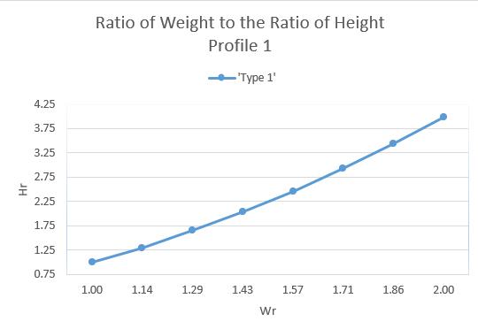
The variation of the Deformation of gravity retaining wall with and without soil structure interaction are plottedagainstheightratioreferringtotableno.5.2
The deformations are obtained by considering only retainingwall,retainingwallwithsoilasawholemass (soil and retaining wall as whole structure), only retainingwallwithsoilmass(consideringsoilstructure interaction)
HeightRatio 1 1.14 1.29 1.43 1.57 1.71 1.86 2 Deformation % 0.44 0.03 0.08 0.65 1.86 0.18 0.03 0.05
Thedeformationratioisdefinedforthecomparingresultsof variousHeightsandprofilewhichareplottedinthegraph.
International Research Journal of Engineering and Technology (IRJET) e-ISSN: 2395-0056
Volume: 09 Issue: 10 | Oct 2022 www.irjet.net p-ISSN: 2395-0072
1.ForplotG2showsthat,variationsindeformationcompare tostandardcasewithoutsoilstructureinteraction.
2. In this case, if soil-structure interaction considered, variationofdeformationisobservedforlowerheights,the variationofgravityretainingwallwithSSIareverycloseto withoutSSI.
Thevariationofmaximumstressesingravityretainingwall with and without soil structure interaction are plotted againstheightratioreferringtotable5.
The maximum stresses obtained by considering only retainingwall,retainingwallwithsoilasawholemass(soil+ retainingwallaswholestructure),onlyretainingwallwith soilmass(consideringsoilstructureinteraction)
Themaximumstressratioisdefinedforthecomparing resultsofvariousHeightsofprofilewhichareplottedin thegraph.
FromgraphG3showsthat,variationsinmaximumstresses compared to standard case of without soil structure interaction.
Height Ratio 1 1.14 1.29 1.43 1.57 1.71 1.86 2
Maximum Stresses% 0.48 0.45 0.43 0.42 0.42 0.46 0.44 0.41
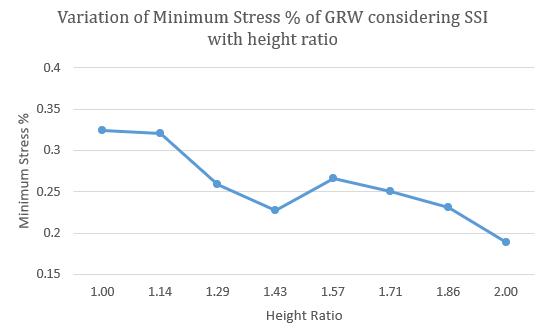
Thevariationofminimumstressesingravityretainingwall with and without soil structure interaction are plotted againstheightratioreferringtotableno.6
The minimum stresses obtained by considering only retainingwall,retainingwallwithsoilasawholemass(soil+ retainingwallaswholestructure),onlyretainingwallwith soilmass(consideringsoilstructureinteraction)
The minimum stress ratio is defined for the comparing resultsofvariousHeightsofprofilewhichareplottedinthe graph. From graph G4 shows that, variations in minimum stressescomparedtostandardcaseofwithoutsoilstructure interaction.
Table 6: Height Ratio & Minimum Stresses values of GRW with and without SSI
HeightRatio 1 1.14 1.29 1.43 1.57 1.71 1.86 2
Minimum Stresses% 0.32 0.32 0.26 0.23 0.27 0.25 0.23 0.19
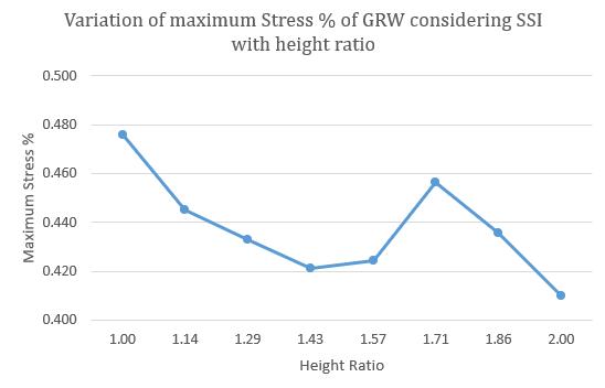
In this case soil structure interaction is considered the differencebetweenresultsofstressesinwhichsoilstructure interactionandwithoutsoilstructureinteractionofgravity retaining wall are varying tremendously. The stresses developed in gravity retaining wall with soil structure interaction are very less as compared to without soil structure interaction. Stress ratio of with soil structure interactionrangesbetween0.40to0.476
Factor value:
Inthiscasevariationsofpercentagesofminimumstresses ratioArenotmuchsignificant.Thelineofthegraphofthis casedecreasesverysilentlyastheratioofheightincreases.
Fromtheresultdiscussinprevious sectionconclusionfor droneasfollows,
Asheightratioincreases,deformationvariesfor1.3height ratioandbelowheightratiothevariationisnegligible.
But, for height ratio more than 1.3 to 1.57 percentage deformationwithrespecttostandardcaseisobservedtobe increase up to 2 %. After 1.57 ratio the deformation percentage are decreased and remain practically constant forheightratio1.6
International Research Journal of Engineering and Technology (IRJET) e-ISSN: 2395-0056
Volume: 09 Issue: 10 | Oct 2022 www.irjet.net p-ISSN: 2395-0072
Thepercentageofstresseswithreferencetoconsideredcase variesalongwithheightratio. Thestressesaredecreasing from 0.48% to 0.42% up to height ratio 1.43. Slightly increasedinthevariationsheisobservedforheightratioin between1.32to1.71 Forhigherheightratiothatisabove 1.71thestressesaredecreases So,fromtheaboveconclusion,ifGRWwithSSIisconsidered only2%stressesareinducedinthecrosssection.
Ifpropercareistakenagainstslidingfactorofsafetysection reductionispossiblewithconsiderationofSSI
[1] Sunil Gupta, Tsung-Wu Lin, Joseph Penzien, ChanShioung Yeh (1980), “HYBRID MODELLING OF SOILSTRUCTURE INTERACTION”, Earthquake Engineering Research Center University of California, Richmond Field Station 47th and Hoffman Blvd. Richmond, California94804,REPORTNO.UCB/EERC-80/09MAY 1980
[2] R. M. Ebeling (1987), “Methods of Evaluating the Stability and Safety of Gravity Earth- Retaining StructuresFoundedonRock”,Informationtechnology Laboratory, 3909 Halls Ferry Road Vicksburg, MS 39180-6199
[3] K.PitilakisandA.Moutsakis(1989),“Seismicanalysis and behavior of G.R.W.- The case of Kalamata harbor quaywall”,SoilandFoundationsVol.29,1-17,Mar1989, Japanese society of soil mechanics and foundation engineering.
[4] Robert M. Ebeling (1990) “Review of finite element proceduresforearthretainingstructure”,Information technology Laboratory, 3909 Halls Ferry Road Vicksburg,MS39180-6199,paperITL-90-5
[5] TimothyD.Stark,StevenM.Fitzwilliam,JoseiphJ.Vettel, Robert M. Ebeling (1991) “Soil-Structure Interaction ParametersforSilts”,TechnicalReportITL-91-2
[6] T.Kupsmy,MarkA.Zarco(1994)“User'sGuideforthe Incremental Construction, Soil-Structure Interaction Program SOILSTRUCT with Far-Field Boundary Elements”,CharlesViaDepartmentofCivilEngineering Vginia Polechnic Intfet and State Unfreety Blackiuurg, VA24061,TechnicalReportITL-94-2
[7] Mete Oner, WilliamP. Dawkins(1997)“Soil-Structure InteractionEffectsinFloodwall”,Professors,Schoolof CivilEngineering,OklahomaStateUniversity,Stillwater, OK.www.ejge.com/1997/Ppr9707/Ppr9707.htm
[8] Cascone, Ernesto; Lo Grasso, Agatino Simone; and Maugeri, Michele (2001), "Dynamic Model Tests on Gravity Retaining Walls with Various Surcharge
Conditions".International Conferences on Recent AdvancesinGeotechnicalEarthquakeEngineeringand Soil Dynamics https://scholarsmine.mst.edu/icrageesd/04icrageesd/s ession07/9
[9] 9. Kenji Watanabe, Yulman Munaf, Junichi Koseki, MasaruTateyama,KenichiKojima(2003),“Behaviorsof Several Types Of Model Retaining Walls Subjected To IrregularExcitation”,SoilAndFoundationVol.43,No.5, 13-17,Oct.2003,JapaneseGeotechnicalSociety.
[10] 10. WANG Jiachun(2005) “Influence Of Different Boundary Conditions On Analysis Of SSI”,18th International Conference on Structural Mechanics in ReactorTechnology(SMiRT18)Beijing,China,August712,2005SMiRT18-K06-1
[11] Dr. P. P. Tapkire (2015),” Optimization of gravity retaining wall profile by introducing cavity”, Head of DepartmentofCivil Engineering ofSinhgadCollegeof Engineering, Solapur, Maharashtra, India (e-mail: pptapkire.nbnscoe@gmail.com).
[12] Ms. Patil Swapnal V. (2015), “Effect of Soil Structure InteractiononGravityDam”,AssistantProfessor,Dept. ofCivilEngg.,JSPM’sImperialCollegeofEngineering& Research,Pune.
Mr. Atul S. Chandanshive B.E.(Civil),MTech(Civil-Structure) (pursuing)ResearchScholaratNB Navale Sinhgad College of Engineering, Solapur, Maharashtra,India

Dr. Pradeep. P. Tapkire working as Head of Department, Civil Engineering,N B NavaleSinhgad College of Engineering, Solapur, Maharashtra, India. Graduated in civil engineering and did masters in structure from Shivaji University, Ph.D. from S.P. Pune University and having experience ofmorethan18yearsinteaching as well as in industry. PG recognized teacher of Solapur University. Has selected as Board of Study Member for Solapur University,Solapur. guided 19PG studentsand16areworkingunder theguidance HandledIITMCband radar installation project as structural and execution expert.

International Research Journal of Engineering and Technology (IRJET) e-ISSN: 2395-0056
Volume: 09 Issue: 10 | Oct 2022 www.irjet.net p-ISSN: 2395-0072
Nominatedasmemberfordistance learning syllabus formation committee IGNOU, Delhi. Also worked as committee member to identify centers for IGNOU for distance learning courses. Receivedappreciationawardfrom ULTRATECH, Cement Solapur for contributioninM-sandProject.
2022, IRJET | Impact Factor value: 7.529 | ISO 9001:2008 Certified Journal | Page1021