International Research Journal of Engineering and Technology (IRJET) e-ISSN: 2395-0056

Volume: 09 Issue: 10 | Oct 2022 www.irjet.net p-ISSN: 2395-0072
DESIGN AND ANALYSIS OF HELICOPTER MAIN ROTOR HEAD
M.
Akhila1
, S.Vivekananda2
1MTECH Student of Mechanical Engineering Department, Machine Design, Malla Reddy College of Engineering and Technology, Hyderabad, Telangana, India, akhila.muruganparvathy@gmail.com
2 Assistant Professor, Dept. of Mechanical Engineering, Malla Reddy College of Engineering and Technology, Hyderabad, Telangana, India, somavivek@mrcet.ac.in ***
Abstract - The rotating component of a helicopter that produces lift is called the rotor system. The hub, rotor blades, and mast make up this rotor. A mast is a hollow, cylindrical metal shaft that stretches upward and is propelled. It is occasionally additionally supported by a transmission. In this scenario, a rotor hub must support the weight of the blades as well as aerodynamic forces. The strength of the helicopter blades and rotor hub will be determined. The rotor blades' attachment point to a top is a mast (hub).The helicopter main rotor head consist of rotor hub, mash, rotor blade and a swash plate. The Helicopter Rotor Head Model and Assemble will be completed, along with theoretical calculations, a Structural Analysis & Modal Analysis on two different materials for the Helicopter Rotor Head, and analysis in ANSYS. In order to calculate displacements and stresses under static conditions, structural analysis is used. A three component system's vibration characteristics (natural frequencies & mode shapes) are determined via modalanalysis.
The main focus of this study was the modeling and analysis of the helicopter rotor head. SOLIDWORKS, a cutting-edge modeling programme, was used to model and assemble the components . InANSYS 2022 R2, ananalysis is performed.
Key Words: Analysis, Optimization, Solid works (Modelling), ANSYS (Static structural analysis, Fatigue analysis,modalanalysis).
1. INTRODUCTION
Althoughhelicoptersexistinawiderangeofsizes and designs, the most of them have similar main parts. A chapterintroducesthemainportionsandcomponentsofa helicopter as well as the systems that go along with it. Knowing how a helicopter's parts and systems function helps a pilot see problems and potential emergency situations more quickly. A revolving component of a helicopter that produces lift is the rotor system. A mast, hub, and rotor blades make up a rotor. A mast is an upward-extending hollow cylindrical metal shaft that is poweredbyandoccasionallysupportedbyatransmission. Ahub,whichservesasarotorblade'sconnectionpoint,is located at the top of a mast. There are several different waystoattachrotorbladestoahub.Thewayamainrotor
bladeisattachedtoandmovesinrelationtoa mainrotor hub determines what type of main rotor system it is. Semirigid, rigid, or completely articulated are the three fundamental categories. An designed combination of ase typesisusedinseveralcontemporaryrotorsystems,such asbearinglessrotorsystems.
2. LITERATURE REVIEW
Richard L. Rotelli, Jr. did a three-dimensional stressanalysisofanewmainrotorhubdesignforanSH-2F helicopterusingacyclesymmetryfeatureofMSC/NASTAN The investigation used cyclic symmetry. A one-eighth symmetry finite element model was made using the FEMGEN interaction graphics mesh generator. A graphic representation of the structural reaction of a rotor hub to various loading situations, as predicted by MSC/NASTAN, was provided using an interactive results viewing tool developedbyFEMGEN.Anovel designfora primaryrotor hub benefited from the NASTRAN analysis results when theywerepresentedinthismanner.
Modes form and harmonic analysis of various helicopter blade architectures by Yon CHEVALIER,Abd-elKader NOUR, and Mohamed Tahar GHERBI. This research focuses on the helicopter blade's dynamic behaviour. A goal is to mimic the behaviour of a blade made of various materials under an aerodynamic force using the finite elementsapproach.Thisstudywascarriedouttocompute thestressesoperatingonastructureforvariousmodesand to analyse the aerodynamic loads imposed and evaluated using a numerical simulation of frequencies and Eigen modes.Thedeterminationofvibrationresponsesresulting from unbalance and other stimulation modes has been madepossiblethroughthestudyoftransientbehaviour.
Moritz Grawunder, Roman Reß, Victor Stein, Christian Breitsamter, and Nikolaus A. Adams, "Flow Characteristics of a Five-Bladed Rotor Head," This paper gives an examination of the flow properties, including cyclic pitch, of a spinning five-bladed rotor head. Finding opportunities for efficiency gains is a key goal. Through numerical simulations based on incompressible unstable Reynolds average Navier Stokes equations, findings are produced. Mesh deformation is used to simulate cyclic pitchmotion.Itisdemonstratedthatapitchcontrolsystem
International Research Journal of Engineering and Technology (IRJET) e-ISSN: 2395-0056
Volume: 09 Issue: 10 | Oct 2022 www.irjet.net p-ISSN: 2395-0072
significantly increases parasite drag. Thus, there is potential for reducingdragby increasing the aerodynamic fairingofasecomponents.Additionally,itisdemonstrated thattheaerodynamicpropertiesaresignificantlyimpacted bythecyclicpitchmotionofabladecuff.
3. METHODOLOGY
For improved performance, the design and material of the helicopter's main rotor head have been adjusted. The main rotorheadofthehelicoptershould be optimised for durability, toughness, high dimension stability, wear resistance, strength, and cost of materials aswellaseconomicconsiderations.
• Perform Helicopter Main Rotor Head design in Solidworks based on design calculation and design model dimension.
•Makedesign calculationsforvarioustypes of Helicopter MainRotorHead.
• To create a solid works model of the helicopter's main rotor head's structural integrity Analytical calculations wereutilisedtocalculateapart'sdimensions,whichwere thenappliedtomodelling.Abaseofthemainrotorheadof the helicopter was an extruded object. On a top, extruded cut profiles were used. An ANSYS workbench model was importedafterbeingsaved.
•Tocreateandstorestatic,modal,andfatigueanalysesfor ahelicoptermainrotorhead'sstructuralstudyinANSYS
• Following the completion of a finite element analysis, data collection, and comparison of the designs for helicopter main rotor heads, By experimenting with several materials, choose the optimum material that will work for the helicopter's main rotor head (steel or alluminium)
• Perform static analysis where force, displacement, total deformation,andequivalentstressaredetermined.
• Perform a fatigue analysis, which determines a fatigue lifeandafatiguesafetyfactor.
• determine the natural frequency and perform modal analysisatvariousfrequencies.
• Perform a modal analysis, which identifies various modesatvariousfrequencies.
•HelicopterdesignVariousmaterialsareanalysedforthe Main Rotor Head, and data is gathered to determine whetherthedesignissafeornot.
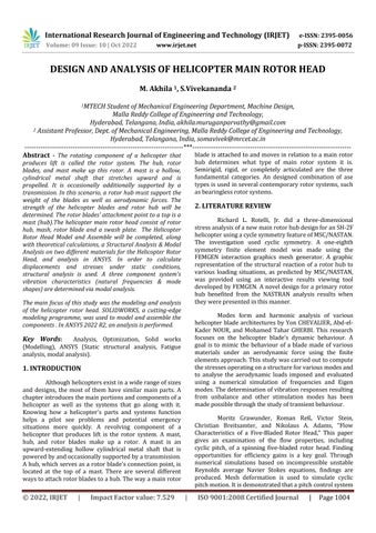
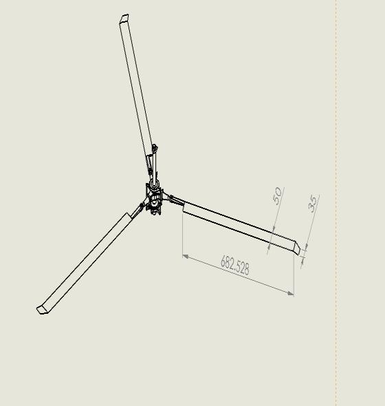
4. HELICOPTER MAIN ROTOR HEAD DIMENSIONS
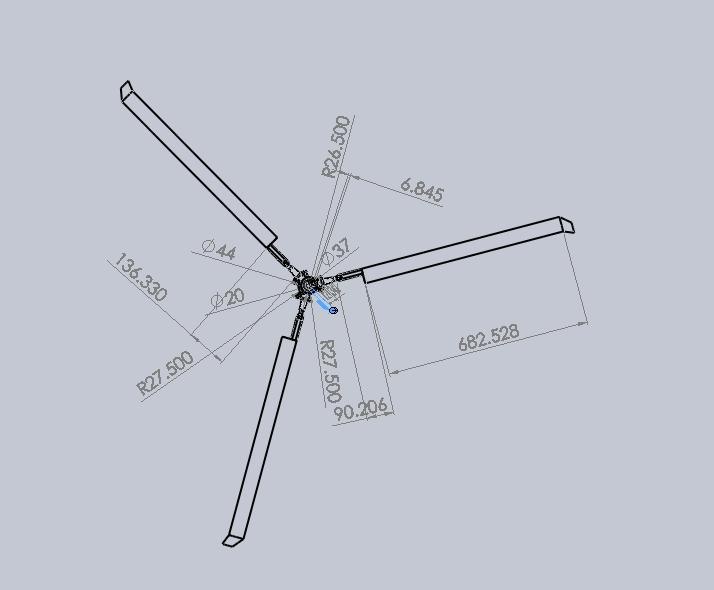
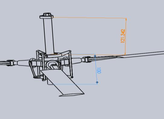
For improved performance, the design and material of the helicopter's main rotor head have been adjusted. The main rotorheadofthehelicoptershould be optimised for durability, toughness, high dimension stability,wear
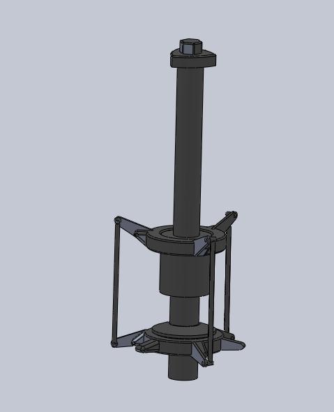
Figure 1: sideview1
Figure 2: sideview2
Figure 3: dimensionofHelicopterrotorheadtopview
International Research Journal of Engineering and Technology (IRJET) e-ISSN: 2395-0056
Volume: 09 Issue: 10 | Oct 2022 www.irjet.net p-ISSN: 2395-0072
5.2.1 Specification of Coaxial helicopters
Length: 16m(52ft6in)
Height: 4.93m(16ft2in)
Emptyweight: 7,700kg(16,976lb)
Grossweight: 9,800kg(21,605lb)
Maxtakeoffweight: 10,800kg(23,810lb)
Powerplant: 2×KlimovVK-2500 turboshaftengines,1,800 kW(2,400shp)each
Mainrotor diameter: 2×14.5m(47ft7in)
Mainrotorarea: 330.3m2(3,555sqft) contra-rotating3-bladed mainrotors
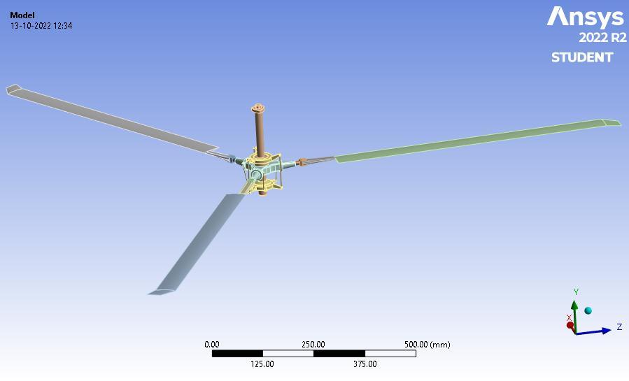
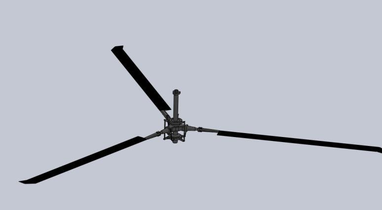
Figure4:isometricview
5. ANALYTICAL DESIGN OF HELICOPTER MAIN ROTOR HEAD
5.1 Design Specifications conditions
Analyzing the benefits and drawbacks of various rotor head designs was the first step in the rotor head selectionprocess.Thefollowingcriteria fora design were decidedupon:
1. diameterofarotorwouldbeapproximatelyonemeter
2. rotorheadshouldbefullyarticulatedandCoaxial
3. blades must be easily interchangeable to test different designs
4. numberofbladesshouldbevariable
parametersweremetbyafinaldesign,whichwas builtbasedona Coaxial system.Changing a total number of blades can be accomplished by removing a blade grip assemblies and reattaching amtoa differenthub built for a appropriate number of blades. Individual blades are changed by disconnecting am from a blade grip and attachinganewblade.
5.2 Design Specifications
We are going to design a helicopter main rotor headusinganalyticalmethodofcalculationforthattaking somestandardspecificationaregivenonfollowingTable
Table 1:
SpecificationofCoaxialhelicopters
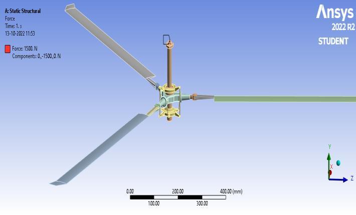
Kindofload
ValueUnit Aerodynamiclift force
1500N
Centrifugalforceofa blade 6156N Aerodynamicdrag forceofablade 40N Torque 160Nm Rotationalspeed 180rad/s
Table 2:LoadsinCoaxialhelicopters
5.3 Design Calculations
5.3.1 Blade sizing
A very first step of our design is to determine a dimension of a rotor blade of a rotor mechanism. This part is done by following various design approach of RC helicopterblades.
Aprimaryassumptionofadimensionforabladeis,Disc radius=Bladespan=R=0.5m,BladeChord=C=0.1m, N=Numberofblades
FromBladeelementaryaory, SolidityFactor,SolidityFactor, ��=(BladeArea)/(DiscArea)=((N×C))/(π×R)
Now,For3Blade,N=3,SolidityFactor,
International Research Journal of Engineering and Technology (IRJET) e-ISSN: 2395-0056
Volume: 09 Issue: 10 | Oct 2022 www.irjet.net p-ISSN: 2395-0072
��=((3×0.1))/((π×0.5))=0.191
Again,For2Blade,N=2,SolidityFactor, ��=((2×0.1))/((π×0.5))= 0.127
Liftcurveslope, a= Here,a0=FirstterminFourierseries=2π/radE= OswaldEfficiencyFactor=0.9AR=aspect ratio=R/C= 0.5/0.1=5So,LiftCurveslope, a= =4.34/rad
Now,FlappingFrequency, λ= [√( ) ] λ [√( ) ]=0.5381 Here,θ=Pitchangleofabladevaries from 0-120
Angularvelocityforarotorblade, =2×(π/60)×N=2×(π/60)×3=0.3151
Andbladetipvelocity, VT=0.5× =0.5×0.3141=0.1570 coefficientofthrust CT=4λ 2=4×0.53812=2.1524 Thrust, T=0.5×1.225×0.15702 ×0.7853×2.1524 =0.02551 Here, DensityofAir,ρ=1.225kg/m3 Area=0.7853981634m2 Coefficientofpower, CP =4λ3=4×0.53813=0.6232
Power, P=0.5×ρ×VT3 ×A×CP =0.5×1.225×0.15703 ×0.7853× 0.6232=1.1600×10 -3 Here,
DensityofAir,ρ=1.225kg/m3 Area=0.7853981634m2
In order to determine if a rotor head design will withstand a forces it will be subjected to during normal operations, a maximum forces and moments were calculated.Aforceswereneededtocalculateastresseson individual components while a moments were used to calculate a coning angle. By calculating a coning angle it waspossibleto evaluation ofa various forcecomponents. A two most significant forces and moments on a componentsarethosegeneratedbyacentrifugalforceand aliftforce
Arotorheadisdesignedtooperatebetween1000 to1350rpmswithamaximumradiusof0.6meters based on this a forces and moments are calculated using 1500rpms.Byusing1500rpmamarginofsafetywasbuilt directly into a calculations. When a moment generated by centrifugalforceandmomentgeneratedbyliftareequala coninganglecanbecalculated.
6. RESULT AND DISCUSSION
6.1 3D Model in Solidworks
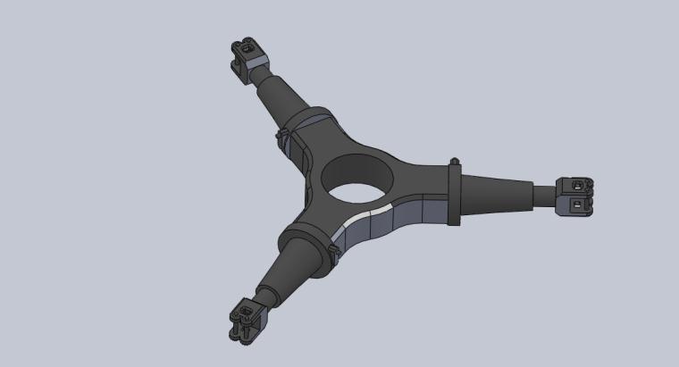
Figure 5:PartDesignofBlade
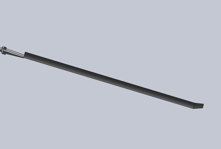
Figure 6: PartDesignofHelicoptermainrotorHub
© 2022, IRJET | Impact Factor value: 7.529 | ISO 9001:2008 Certified Journal | Page1007
International Research Journal of Engineering and Technology (IRJET) e-ISSN: 2395-0056
Volume: 09 Issue: 10 | Oct 2022 www.irjet.net p-ISSN: 2395-0072
International Research Journal of Engineering and Technology (IRJET) e-ISSN: 2395-0056
2395-0072
Time [s] Minimum [MPa] Maximum [MPa] Average [MPa] 1. 38096e-007 88663 11991
Table 4: equivalentstress
6.4.2 Fatigue analysis
Figure 14: force2
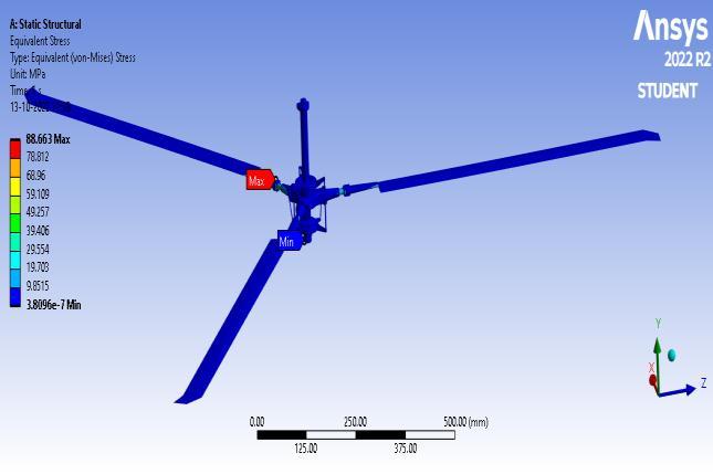
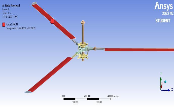
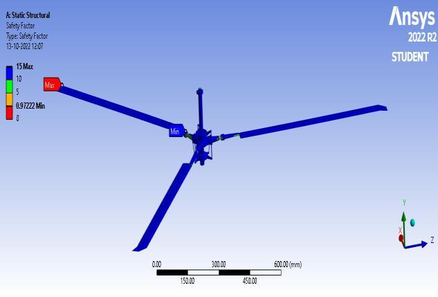
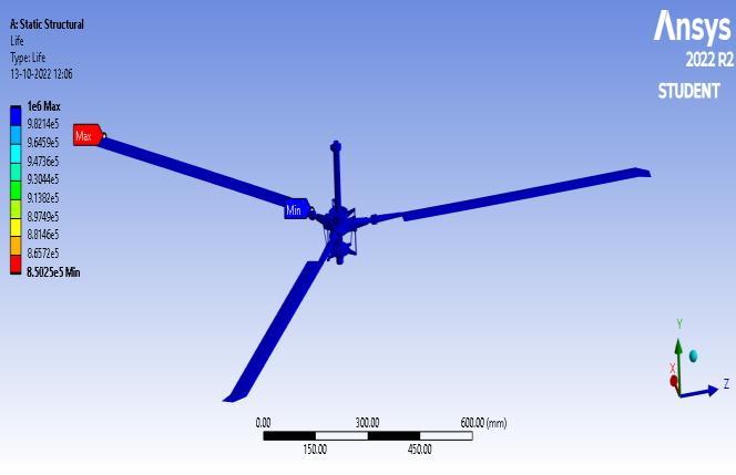
Figure 17: life-steelmaterial
Figure 18: safetyfactor-steelmaterial
Time[s] Minimum Maximum Average 1. 8.5025e+005 1.e+006 1.e+006
Table 5: life
Time[s] Minimum Maximum Average 1. 85025e+005 1e+006 1e+006
Table 6: safetyfactor
International Research Journal of Engineering and Technology (IRJET) e-ISSN: 2395-0056

International Research Journal of Engineering and Technology (IRJET) e-ISSN: 2395-0056
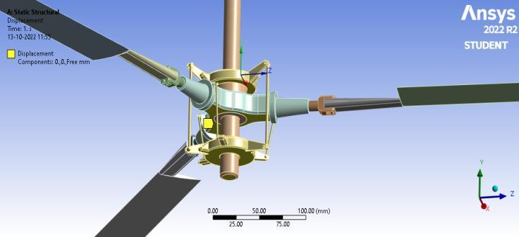
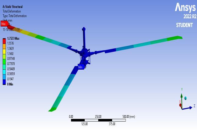
Time [s] Minimu m[mm] Maximum [mm] Average[mm] 1. 0 49236 090716
Table 8: totaldefornation
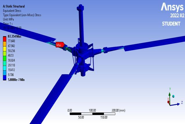
Time [s] Minimum [MPa] Maximum [MPa] Average [MPa] 1. 5.8888e-007 87.354 1.2
Table 9: equivalentstress
6.5.2 Fatigue analysis
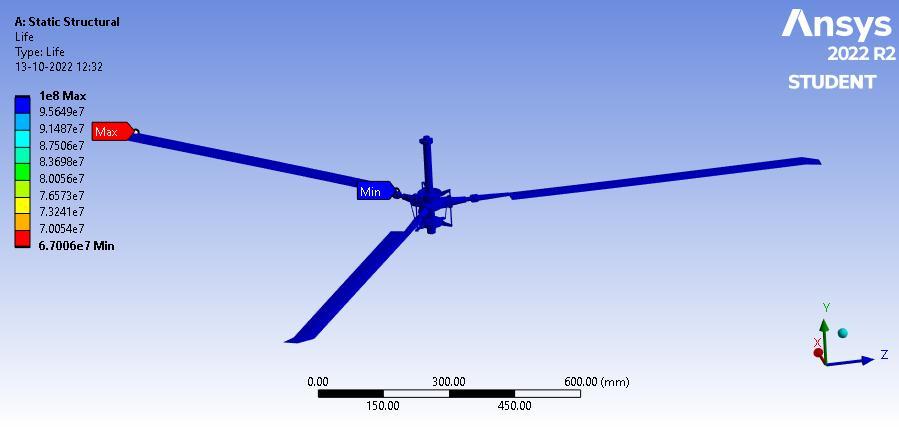
Figure25: life-Aluminiummaterial
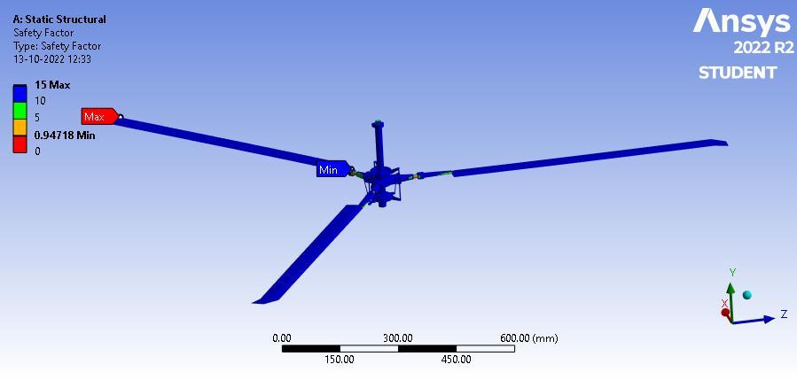
Time[s] Minimum Maximum Average 1. 094718 15. 14763
Table 11 : safetyfactor
Figure 26: safetyfactor-Aluminiummaterial
Time [s] Minimum Maximum Average 1. 6.7006e+007 1.e+008 1.e+008
Table 10 : life
Figure 31: FatigueSensitivity
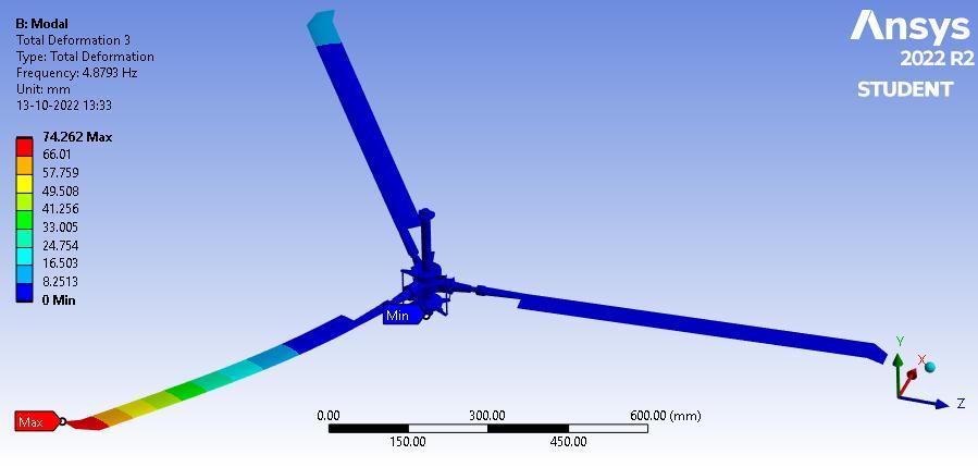
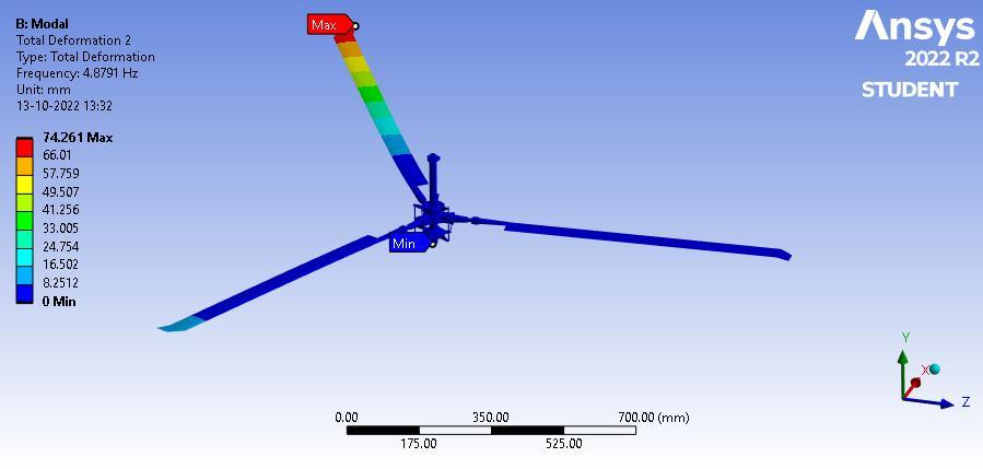
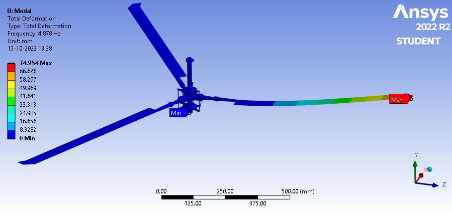
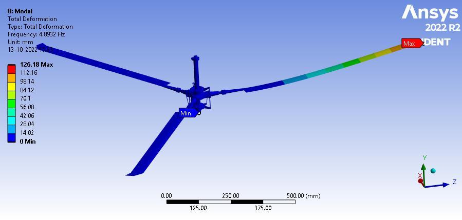
6.5.3 Modal analysis
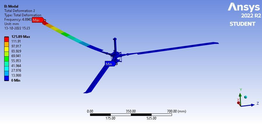
Figure 27: totaldeformation1-Aluminiummaterial
Figure 28: totaldeformation2-Aluminiummaterial
Volume: 09 Issue: 10 | Oct 2022 www.irjet.net p-ISSN: 2395-0072 © 2022, IRJET | Impact Factor value: 7.529 | ISO 9001:2008 Certified Journal | Page1011
International Research Journal of Engineering and Technology (IRJET) e-ISSN: 2395-0056
Volume: 09 Issue: 10 | Oct 2022 www.irjet.net p-ISSN: 2395-0072
Strength Coefficient z(MPa)
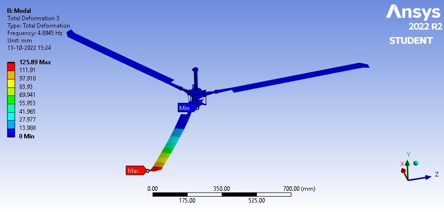
Figure 29: totaldeformation3-Aluminiummaterial Mode Frequency[Hz] Maximum[mm] 1. 4.8932 126.18 2. 48943 125.89 3. 48945 125.89
Table 12 : Frequency Compressive Ultimate StrengthMPa
Compressive YieldStrength MPa
Tensile Yield Strength MPa
Tensile Ultimate Strength MPa 0 250 250 460 Table 13: Structuralsteelparameter
AlternatingStressMPa Cycles MeanStressMPa 3999 10 0 2827 20 0 1896 50 0 1413 100 0 1069 200 0 441 2000 0 262 10000 0 214 20000 0 138 1.e+005 0 114 2.e+005 0 86.2 1.e+006 0 Table 14: S-NCurveofStructuralsteel
Strength Expone n-t
Ductility Coefficie n-t
Cyclic Strength Coefficie nt(MPa}
Cyclic Strain Hardenin g Exponent 920 0.106 0.213 1000 0.2
Table 15: Strain-LifeParametersofStructuralsteel Young's Modulu sMPa
Poisson' sRatio Bulk Modulus MPa
Shear Modulu sMPa
Relative Permeabilit y 2.e+00 5 0.3 1.6667e+00 5 76923 10000
Table 16: IsotropicElasticityofStructuralsteel
Compressive Ultimate StrengthMPa
Compressive YieldStrength MPa
Tensile Yield Strength MPa
Tensile Ultimate Strength MPa 0 280 280 310
Table 17 : alluminiumalloyproperties
AlternatingStress MPa Cycles R-Ratio 275.8 1700 -1 241.3 5000 -1 206.8 34000 -1 172.4 1.4e+005 -1 137.9 8.e+005 -1 117.2 2.4e+006 -1 89.63 5.5e+007 -1 82.74 1.e+008 -1 170.6 50000 -0.5 139.6 3.5e+005 -0.5 108.6 3.7e+006 -0.5 87.91 1.4e+007 -0.5 77.57 5.e+007 -0.5 72.39 1.e+008 -0.5 144.8 50000 0
International Research Journal of Engineering and Technology (IRJET) e-ISSN: 2395-0056
Volume: 09 Issue: 10 | Oct 2022 www.irjet.net p-ISSN: 2395-0072
120.7 1.9e+005 0 103.4 1.3e+006 0 93.08 4.4e+006 0 86.18 1.2e+007 0 72.39 1.e+008 0 74.12 3.e+005 0.5 70.67 1.5e+006 0.5 66.36 1.2e+007 0.5 62.05 1.e+008 0.5
Table 18 : S-NCurveofalluminiumalloy
Young's Modulus MPa
The structural behaviour of the main rotor head of a helicopter was investigated for various materials. A blade weight and aerodynamic forces are carried by the main rotor head of the helicopter in this illustration. In that situation, the strength of the helicopter's main rotor head will be determined. Therefore, a static analysis, fatigueanalysis,andmodalanalysisarecarriedoutonthe main rotor head of the helicopter for various materials, suchassteelandaluminiumalloy.
Equivalent von-Mises stress is lower than yield strength and fatigue limit, thus steel has a lower fatigue life and endurance limit than aluminium. Since steel is lighterthanaluminiumandcanhandleenormousloadsor weight,itisa moreideal material forthemainrotorhead of a helicopter. We discovered a distortion in modal analysisatvariousfrequencies.
7 CONCLUSION
Poisson's Ratio Bulk Modulus MPa
Shear Modulus MPa
Relative Permeability 71000 0.33 69608 26692 1
Table 19 : Aluminumalloyproperty
[1] Manually calculated permissible stress of modified design=11.43N/mm2
Analytically calculated equivalent stress of modified designforsteel=89.445Mpa
Analytically calculated equivalent stress of modified designforaluminum=88.131Mpa
Fatiguelifeofsteel=1×10⁶
Fatiguelifeofaluminum=1×10⁸
FatigueSafetyfactorofsteelandaluminum=15
[2] Equivalentvon-Misesstressesofourhelicopter'smain rotor head design are less than a yield strength. These results have been compared with current results of a similar model under the same loading conditions to validateFEAresults.Theyieldstress,whichis250MPafor steel and 280 MPa for aluminium, is far below the stress value.Analysisrevealedthatthevon-Misesstressesforthe twomaterialswerenearlyidentical.
Tensileyieldstrengthofsteel=250MPa
Tensileyieldstrength ofaluminum=280MPa
Endurancelimitofsteel=230MPa
Endurancelimitofaluminum=310MPa
Extensive historical research makes it evident that the issue has not yet been fully resolved, and designers are still having many difficulties, particularly with stress concentration and the impact of loading other oar variables. The most well-liked strategy for analysing fracture mechanics issues is the finite element approach. Somehelicoptermainrotorheadsmadeofsteelarealmost as lightas those made of aluminium. However, steel's key benefit is that it is more rigid and has higher fatigue strength than aluminium. We can therefore conclude that aluminium is good for producing inexpensive helicopter main rotor heads whereas steel is a better material in terms of strength. SOLIDWORKS was used to successfully complete a project's design. Using SOLIDWORKS, issues that arose during the design of a machine were successfullyresolved.
The majority of the key components of SOLIDWORKS, a flexible and all-inclusive programme for threedimensional solid modelling, were used in the project design.
The primary features used to develop componentsareprotrusionandcut.UsingSOLIDWORKS,a component is drawn very precisely. Hence, When compared to the existing design of the helicopter's main rotor head at the same applied force, the modified design for the variable valve actuation system carries less stress. It demonstrates that a modified helicopter main rotor head is more durable than an existing one over a lengthy period of time, and according to a design assessment, the new design is simpler than the existing one and exhibits less deformation. Equivalent von-Misses stress is smaller than yield strength and fatigue limit. A steel's endurance limit is lower than an aluminium’s in terms of fatigue life. Since steel is lighter than aluminium and can handle
© 2022, IRJET | Impact Factor value: 7.529 | ISO 9001:2008 Certified Journal | Page1013
International Research Journal of Engineering and Technology (IRJET) e-ISSN: 2395-0056
Volume: 09 Issue: 10 | Oct 2022 www.irjet.net p-ISSN: 2395-0072
enormous loads or weight, it is a more ideal material for the main rotor head of a helicopter. We discovered a distortion in modal analysis at various frequencies. Each blade of a rotor responds to inputs from a control system as it rotates, enabling helicopter control. A centre of lift affects pitch, roll, and upward motion on a full rotor systeminresponseto inputs.Thestructuralbehaviourof the main rotor head of a helicopter was investigated for various materials. Here, a helicopter rotor hub must support the weight of the blades and aerodynamic forces as they rotate. In that situation, the strength of the helicopter'smainrotorheadwillbedetermined.
Inthisproject,a3Dmodelofthehelicopter'smain rotor head was created in SOLIDWORKS and imported into the ANSYS software for static, fatigue, and modal analyses to examine its strength and dynamic properties. The model was then optimised using various materials, suchassteelandaluminiumalloy.
The main rotor head of a helicopter has stresses and deflections within the design parameters of the materials employed, according to the structural analysis discussed above. We can infer from the data that a steel material model for the helicopter main rotor hub had better FOS andweightreductionthananoarmaterialmodel.
By altering the way a stress in a helicopter's main rotor headvariedunderheavyloadconditions,wewereableto make this observation. We have suggested the optimum material for a helicopter's main rotor head under conditions of heavy stress. The effects of loading and oar variables,aswellasstressconcentration,aremajorissues for designers. A steel helicopter's main rotor head is almost as light as an aluminium one, and steel has higher stiffnessandfatiguestrengththanaluminium.
REFERENCES
[1]. Design and power transmission of an advanced light helicopter,July-August2013,Prof.AmarnathV.Hegneand Prof.PreethiHegne.
[2]. "Detailed analysis of rotor blades of helicopter" by Hardeep Singh and Jag Sahil Saini, Gurukul Vidyapeeth InstituteofEngineeringandTechnology,September2014.
[3].JagSahilSainiisanengineerandtechnologyprofessor at Gurukul Vidyapeeth Institute. "Analysis of Helicopter RotorBlade"publishedinJune2015Spring2016:Mitchell Brush, Scott Novak, Matthew Montana, and Michael Roemer.
[4]. "The development and study of helicopter rotor blades,"byMitchellBrush,ScottNovak,MatthewMontana, andMichaelRoemer,publishedinApril2016.
[5]ThirdEditionofTheoryofMechanismandMachinesby AmitabhaGhoshandAshok KumarMalikwaspublishedin 1998byAffiliatedpresspvtlimitedinNewDelhi.
[6] Joseph Edward Shigley, Theory of Machines and Mechanisms,TataMcGrawHill,2003,NewYork
[7] Pravallika Reddy, "Static Structural Analysis of a Helicopter Rotor Blade," Department of Aeronautical Engineering, MLR Institute of Technology and Management,Hyderabad,September–December2015.
[8]. 1994's "Design of Machine Elements," by V. Bhandari [9]TataMcGraw-Hill.