International Research Journal of Engineering and Technology (IRJET) e-ISSN:2395-0056

Volume: 09 Issue: 10 | Oct 2022 www.irjet.net p-ISSN:2395-0072
International Research Journal of Engineering and Technology (IRJET) e-ISSN:2395-0056
Volume: 09 Issue: 10 | Oct 2022 www.irjet.net p-ISSN:2395-0072
To meet Power Quality (PQ) standard cutoff points, including some kind of compensation might be essential.Modernarrangementscanbetrackeddownas dynamic correction or dynamic filtering. A shunt dynamicpowerfilterisreasonableforthesuppressionof negative load impact on the supply organization, however in the event that there are supply voltage defects,aseriesdynamicpowerfiltermightbeexpected to give full pay. As of late, arrangements based on Adaptable AC Transmission Systems (Realities) have showed up. The use of Realities ideas in distribution systems has brought about another generation of repaying devices. A Brought together Power Quality Conditioner (UPQC) is the expansion of the Brought together Power-Stream Controller (UPFC) idea at the distributionlevel.Itcomprisesofconsolidatedseriesand shunt converters for concurrent pay of voltage and currentflawsinasupplyfeeder.
An Interline Power-Stream Controller (IPFC) comprisesoftwoseriesVoltage-sourceConverters(VSC) whose dc capacitors are coupled. This permits dynamic power to course between the VSCs. With this configuration, two lines can be controlled at the same time to upgrade the organization use. An Interline Brought together Power-Quality Conditioner (IUPQC), which is the expansion of the IPFC idea at the distribution level. The IUPQC comprises of one series and one shunt converters. It is associated between two feeders to direct the bus voltage of one of the feeders, whilecontrollingthevoltageacrossadelicateloadinthe other feeder. In this configuration, the voltage guideline in one of the feeders is performed by the shunt-VSC. However, starting from the source impedance is exceptionally low, a high measure of current would be expected to boost the bus voltage in the event of a voltagehang/enlargewhichisn'tpossible.Itadditionally has low powerful execution in light of the fact that the dc-connectcapacitorvoltageisn'tcontrolled.
This project presents another brought together power-quality molding system (MC-UPQC), fit for synchronous remuneration for voltage and current in multi-bus/multi-feeder systems. By utilizing one shunt voltage-source converter (shunt VSC) and at least two seriesVSCstheconfigurationismade.Thesystemcanbe applied to neighboring feeders to make up for supply-
voltage and load current blemishes on the fundamental feeder and full remuneration of supply voltage flaws on the other feeders. The configuration will be planned as all converters are associated consecutive on the dc side and share a common dc-connect capacitor. Therefore, power can be moved from one feeder to adjoining feeders to make up for list/swell and interruption. The proposed geography can be utilized for synchronous remuneration of voltage and current blemishes in both feeders by sharing power pay capacities between two nearby feeders which are not associated. The system is likewise fit for making up for interruptions without the requirement for a battery stockpiling system and thusly withoutcapacitylimitrestrictions.Bytherecreationthe exhibition of MC-UPQC as well as the took on control algorithmwillberepresented.
With growing uses of nonlinear and electronically exchanged devices in dispersal systems and ventures, Power Quality (PQ) issues, similar to sounds, flash, and anomaly have become serious concerns. Similarly, lightning strikes on transmission lines, exchanging of capacitor banks, and different association issues can in like manner cause PQ issues, for instance, vagabonds, voltage hang/swell, and impedance. Then again, an addition of touchy weights including automated devices andcomplexcyclecontrollersrequiresapuresinusoidal stockvoltageforauthenticweightaction.
To fulfill PQ rule limits, including some sort of remunerationmightbecentral.Presentdayplanscanbe found as unique revision or dynamic filtering. A shunt dynamicpowerchannelissensibleforthecamouflageof negative weight impact on the stock association, yet if therearesupplyvoltagedeserts,aseriesdynamicpower channel might be supposed to give full compensation. Recently, plans considering Versatile AC Transmission Systems (Real factors) have showed up. The use of Real factors thoughts in scattering structures has brought about another period of compensating devices. It contains solidified series and shunt converters for synchronous remuneration of voltage and current blemishesinastorefeeder.
Lately, multiconverter Real factors contraptions, for instance, an Interline Power-Stream Controller (IPFC) and the Summarized Bound together Power-Stream
International Research Journal of Engineering and Technology (IRJET) e-ISSN:2395-0056
Volume: 09 Issue: 10 | Oct 2022 www.irjet.net p-ISSN:2395-0072
Controller (GUPFC) are introduced. The place of these devices is to control the power stream of multiline or a sub network rather than control the power stream of a lonelineby,forinstance,anUPFC.
It widens the possibility of voltage and power-stream control past what is practical with the known twoconverter UPFC. The most un-troublesome GUPFC contains three converters one related the fundamental GUPFC have some control over full scale five power structure sums, for instance, a vehicle voltage and free unique and responsive power floods of two lines. The possibilityofGUPFCcanbereachedoutforextralinesif major. The device might be presented in a couple of central substations to supervise power floods of multilineoragatheringoflinesandgivevoltagesupport aswell.ByusingGUPFCcontraptions,theexchangelimit of transmission lines can be extended on a very basic level.
Also, by using the multiline-the chiefs limit of the GUPFC, dynamic power stream on lines can't be extended, yet furthermore be diminished concerning workingandmarketexchangeessentials.Allaround,the GUPFC can be used to extend the exchange limit and simplicityblockagesina versatileway.Thisthoughtcan be reached on a mission to design multiconverter game plans for PQ improvement in neighboring feeders. For example, the Interline Brought together Power-Quality Conditioner (IUPQC), which is the extension of the IPFC thoughtatthemovementlevel,hasbeenproposedinthe IUPQCcontainsoneseriesandoneshuntconverter.Itis related between two feeders to control the vehicle voltage of one of the feeders, while coordinating the voltage across a sensitive weight in the other feeder. In this plan, the voltage rule in one of the feeders is performed by the shunt-VSC. Nonetheless, beginning from It also has low powerful execution in light of the way that the dc-associate capacitor voltage isn't coordinated.
Inthisendeavor,anotherplanofanUPQCassembledthe Multiconverter Bound Power-Quality Conditioner (MCUPQC) is presented. The structure is stretched out by adding a series-VSC in a coterminous feeder. The proposed geography can be used for concurrent compensation of voltage and current blemishes in the two feeders by splitting power remuneration limits betweentwo neighboringfeeders whichare not related. The structure is in like manner prepared for compensating for obstructions without the necessity for a batterystoring system andconsequently without limit limits.
ThecourseofactionofbothDSTATCOMandDVRhavea few control over the power idea of the source current
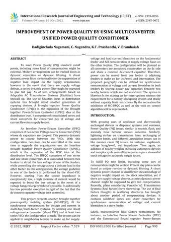
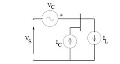
and the heap transport voltage. Additionally, accepting that the DVR and STATCOM are related on the DC side, theDCtransportvoltagecanbecoordinatedbytheshunt related DSTATCOM while the DVR supplies the normal energy to the heap in case of the transient aggravations in source voltage. The setup of such a contraption (named as Brought together Power Quality Conditioner (UPQC))isshowninFig.Thisisanadaptablecontraption like an UPFC. Regardless, the control objectives of an UPQCareextremelynotequivalenttothatofanUPFC.
The shunt related converter has the going with control targets:
1. To balance the source streams by injecting negativeandzeroplanpartsanticipatedbytheheap.
2. The make up for the music in the heap current by imbuingtheessentialconsonantstreams.
3. To control the power factor by implanting the importantopencurrent(atfundamentalrepeat).
4.TocoordinatetheDCtransportvoltage.
The series related converter has the going with control targets:
1. To change the voltages at the heap transport by implanting negative and zero grouping voltages to compensateforthosepresentinthesource.
2.To bind the heap transportfrom musicpresentinthe sourcevoltages,bymixingthesymphoniousvoltages
3. To control the size of the heap transport voltage by injecting the vital dynamic and open parts (at head repeat) dependent upon the power factor on the source side
4. To control the power factor at the data port of the UPQC (where the source is related. Note that the power
International Research Journal of Engineering and Technology (IRJET) e-ISSN:2395-0056
Volume: 09 Issue: 10 | Oct 2022 www.irjet.net p-ISSN:2395-0072
factorattheoutcomeportoftheUPQC(relatedwiththe heap)iscompelledbytheshuntconverter.
OF UPQC
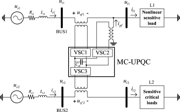
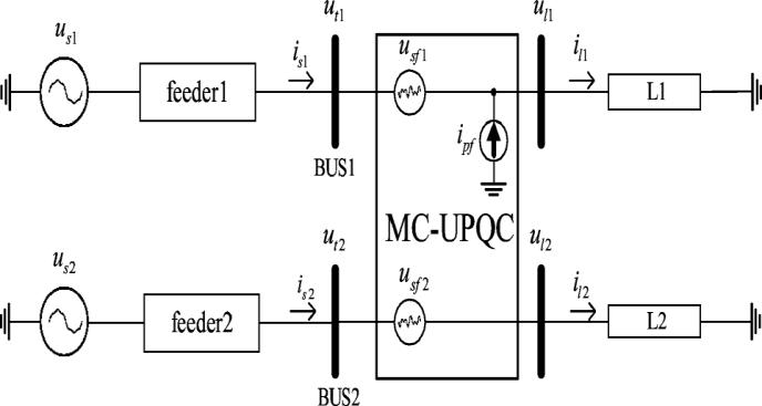
Single-line diagram of a distribution system with an MC-UPQC.
Asshowninfigure.5.1,twofeedersrelatedwith two unmistakable substations supply the heaps L1 and L2.TheMC-UPQCisrelated withtwovehiclesBUS1and BUS2 with voltages of ut1 and ut2, independently. The shunt part of the MC-UPQC is similarly connected with loadL1withacurrentofil1.Supplyvoltagesareimplied by us1 and us2 while load voltages are ul1 and ul2 Finally, feeder streams are shown by is1 and is2 load streams are il1 and il2 Transport voltages ut1 and ut2 are distorted and might be presented to hang/develop. TheheapL1isanonlinear/touchyweightwhichneedsa pure sinusoidal voltage for real movement while its currentisnon-sinusoidalandcontainssounds.Theheap L2 is a fragile/essential weight which needs a basically sinusoidalvoltageandshouldbetotallyshieldedagainst mutilation, hang/swell, and obstruction. These sorts of weights essentially integrate creation undertakings and fundamental expert centers, as clinical centers, air terminals, or broadcasting centers where voltage impedancecanachieveoutrageousjudiciousincidentsor humanharms.
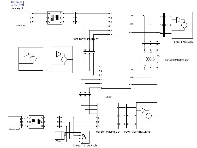
Typical MC-UPQC used in a distribution system.
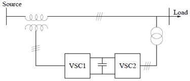
Intheproposedconfiguration,VSC1 isconnected in series with BUS1 and VSC2 is connected in parallel with load L1 at the end of Feeder1. VSC3 is connected in serieswithBUS2 attheFeeder2 end.
Therewardreactor(Lf)andhigh-passyieldchannel(Rf, Cf) related with thwart the movement of exchanging music into the power supply. As shown in Fig 5.2, all converters are given from a common dc-interface capacitor and related with the movement system throughatransformer.
Discretionary (scattering) sides of the series-related transformers are straightforwardly connected in series withBUS1andBUS2,andthehelper(spread)sideofthe shunt-related transformer is related in agreed with load L1.
ThemarksoftheMC-UPQCshowedinFig5.2are:
1) To direct the heap voltage (ul1) against hang/swell and aggravations in the structure to defend thenonlinear/sensitiveweightL1,
2) To direct the heap voltage ul2 against hang/swell, impedance, and aggravations in the system toshieldthefragile/fundamentalweightL2,
3) To compensate for the responsive and consonantpiecesofnonlinearweightcurrent(il1).
International Research Journal of Engineering and Technology (IRJET) e-ISSN:2395-0056
Volume: 09 Issue: 10 | Oct 2022 www.irjet.net p-ISSN:2395-0072
To accomplish these targets, series VSCs (i.e., VSC1 and VSC3) fill in as voltage controllers while the shunt VSC (i.e.,VSC2)functionsasacontinuouscontroller.
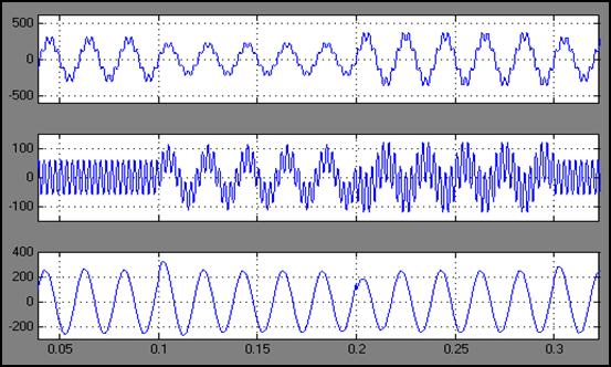
Likewise, the BUS2 voltage, the relating pay voltage infusedbyVSC3,lastly,theheapL2voltagearedisplayed in Fig. 6.3. As displayed in these figures, contorted voltages of BUS1 and BUS2 are sufficiently made up for across the heaps L1 and L2 with awesome powerful reaction.
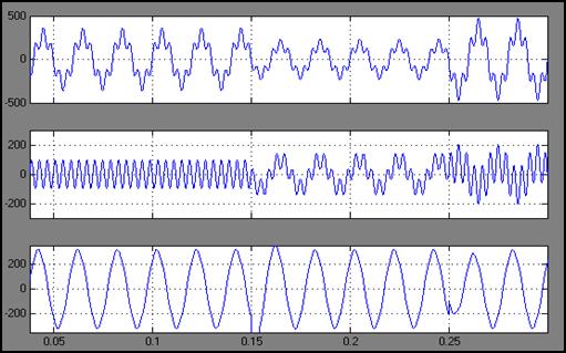
Permit us to consider that the power structure in containstwothree-stagethree-wire380(v)(rms,L),50Hz utilities. The BUS1 voltage contains the seventhdemand symphonious with a worth of 22%, and the BUS2 voltage contains the fifth solicitation consonant with a worth of 35%. The BUS1 voltage contains 25% hang among s and 20% swell betweens. The BUS2 voltagecontains35%rundownbetweensand30%swell betweens. The nonlinear/sensitive weight L1 is a threestage rectifier load which supplies a RC heap of 10 and 30 F. Finally, the fundamental weight L2 contains a sensibleRLheapof10and100mH.
The MC-UPQC is turned on at 0.02 s. The BUS1 voltage, the relating pay voltage mixed by VSC1, finally loadL1voltageareshowninFig.6.2Inallfigures,simply thestagewaveformisshownforease.
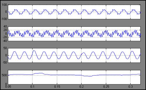
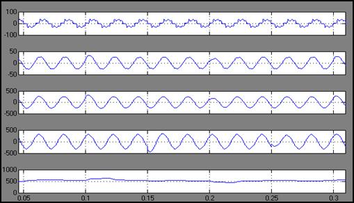
Thenonlinearburdencurrent,itscomparingpaycurrent infused by VSC2, repaid Feeder1 current, and, at long last, the dc-connect capacitor voltage are displayed in Fig. 6.4. The twisted nonlinear burden current is repaid quite well, and the all out consonant bending (THD) of the feeder current is diminished from 28.5% to under 5%.Likewise,thedcvoltageguidelinecirclehasworked appropriately under all aggravations, like hang/enlarge inthetwofeeders.
Load voltage in feeder 2
Feeder 1 current
Load voltage in feeder 1 Capacitor voltage
International Research Journal of Engineering and Technology (IRJET) e-ISSN:2395-0056
Volume: 09 Issue: 10 | Oct 2022 www.irjet.net p-ISSN:2395-0072
Right when a shortcoming happens in Feeder2 (in a L-G, L-G, and L-G faults), the voltage across the touchy/fundamental weight L2 is locked in with hang/swell orimpedance.This voltage imperfection can becompensatedforbyVSC2.
For this present circumstance, the power expected by load L2 is given through VSC2 and VSC3. This recommends that the power semiconductor switchesofVSC2andVSC3shouldbeassessedtosucha degree that hard and fast power move is possible. This might fabricate the cost of the device, however the benefitthatmightbeobtainedcanoffsettheexpense.
In the proposed game plan, the touchy/fundamental weight on Feeder2 is totally defended against bending, hang/swell, and obstruction. Besides, the controlled voltageacross the touchyweight on Feeder1 can supply a couple of clients who are similarly protected against distortion, hang/extend, and transientobstruction.Inthismanner,thecostoftheMCUPQC should be changed against the cost of impedance, considering reliability records, for instance, the client ordinary obstruction length list (CAIDI) and client typical impedance repeat document (CAIFI). It is ordinarythattheMC-UPQC costcanberecuperatedina couple of years by charging higher duties for the shieldedlines.
Toassesstheframeworkconductduringaheap change, the nonlinear burden L1 is multiplied by diminishing its protection from half at 0.5 s. The other burden, notwithstanding, is kept unaltered. The frameworkreactionisdisplayedinFig.6.6.Ittendstobe seen that as burden L1 changes, the heap voltages and stay undisturbed, the dc transport voltage is managed, andthenonlinearburdencurrentisredressed.
The introduction of the MC-UPQC under an issue condition on Feeder2 is attempted by applying a threestage shortcoming to ground on Feeder2 between s. ReenactmentresultsareshowninFig.6.5.
The control systems for shunt and series VSCs, which are introduced in Portion II, rely upon thetechnique. They are prepared for compensating for the inconsistentsourcevoltageandlopsidedweightcurrent. To survey the control structure limit with respect to unbalanced voltage remuneration, another reenactment isperformed.In thisnewpropagation, theBUS2 voltage and the consonant pieces of BUS1 voltage resemble those given in Fragment IV. Nonetheless, the fundamental piece of the BUS1 voltage is a lopsided three-stage voltage with an unbalance component of 40%.Thisunbalancevoltageisgivenby
International Research Journal of Engineering and Technology (IRJET) e-ISSN:2395-0056
Volume: 09 Issue: 10 | Oct 2022 www.irjet.net p-ISSN:2395-0072
[1] D. D. Sabin and A. Sundaram, “Quality enhances
reliability,” IEEE Spectr., vol. 33, no. 2, pp. 34–41, Feb.1996.
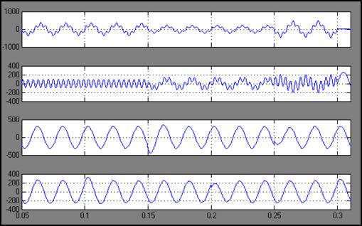
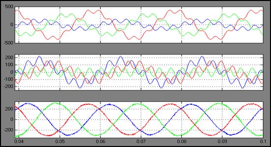
The multiplication results for the three-stage BUS1 voltage, series pay voltage, and weight voltage in feeder 1 are shown in Fig. 6.8. The reenactment results show that the consonant parts and unbalance of under disproportionate source voltage for by injecting the proper series voltage. Here, the heap voltage is a threestagesinusoidaloffsetvoltagewithcontrolledadequacy
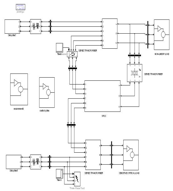
Simulation diagram of MC-UPQC for showing results in unbalanced condition.
[2] M. Rastogi, R. Naik, and N. Mohan, “A comparative evaluation of harmonic reduction techniques in three-phase utility interface of power electronic loads,” IEEE Trans. Ind. Appl., vol. 30, no. 5, pp. 1149–1155,Sep./Oct.1994.
[3] F. Z. Peng, “Application issues of active power filters,”IEEEInd.Appl.Mag.,vol.4,no.5,pp.21–30, Sep../Oct.1998.
[4] H. Akagi, “New trends in active filters for power conditioning,” IEEE Trans. Ind. Appl., vol. 32, no. 6, pp.1312–1322,Nov./Dec.1996.
[5] L. Gyugyi, C. D. Schauder, S. L. Williams, T. R. Rietman, D. R. Torjerson, and A. Edris, “The unified power flow controller: A new approach to power transmission control,” IEEE Trans. Power Del., vol. 10,no.2,pp.1085–1097,Apr.1995.
[6] H. Fujita and H. Akagi, “The unified power quality conditioner: The integration of series and shunt active filters,” IEEE Trans. Power Electron., vol. 13, no.2,pp.315–322,Mar.1998.
BUS1 voltage, series compensating voltage and load voltage in Feeder1 under unbalanced source voltage.
In this assignment, another setup for synchronous compensation of voltage and current in bordering feeders has been proposed. The new plan is named multi-converter bound together power-quality conditioner(MC-UPQC).Appeareddifferentlyinrelation to a common UPQC, the proposed geography is ready to do totally shielding fundamental and fragile weights against mutilations, hangs/swell, and break in twofeederstructures.
Benefits:
1) Power move between two bordering feeders for list/swellandobstructionpay;
2) Pay for obstructions without the necessity for a battery storing structure and, thusly, without limit obstacle;
3) Splitting power pay limits between two bordering feederswhicharenotrelated.
[7] A. Ghosh and G. Ledwich, “A unified power quality conditioner (UPQC) for simultaneous voltage and current compensation,” Elect. Power Syst. Res., pp. 55–63,2001.
AUTHORS
1. BADIGINCHULA NAGAMANI, M.TechScholar
Dept.ofElectrical&ElectronicsEngineering, TECHCOLLEGE,TADIPATHRI.
2. C. NAGENDRA, AssistantProfessor, Dept.ofElectrical&ElectronicsEngineering, TECHCOLLEGE,TADIPATHRI.
3. K.T.PRASANTHI, AssistantProfessor, Dept.ofElectrical&ElectronicsEngineering, TECHCOLLEGE,TADIPATHRI.
4. V. BRAMHAIAH AssistantProfessor, Dept.ofElectrical&ElectronicsEngineering, TECHCOLLEGE,TADIPATHRI.