International Research Journal of Engineering and Technology (IRJET) e-ISSN: 2395-0056
Volume: 09 Issue: 10 | Oct 2022 www.irjet.net p-ISSN: 2395-0072
International Research Journal of Engineering and Technology (IRJET) e-ISSN: 2395-0056
Volume: 09 Issue: 10 | Oct 2022 www.irjet.net p-ISSN: 2395-0072
1, 2, 3, 4,
Abstract: The purpose of this paper is to describe, in detail, the process of planning, executing, and working on an autonomous inventory bot. This paper provides a brief overview of the project, the scope of the robot, the building, and the economic analysis of the system. The working, construction, digital design, and modelling of the robot are explained in detail. The specifications of this project include, butnotlimitedto,use ofArduinoMegaMicrocontrollerasthe main controller, the navigation of shelves independently, led indicators notifying the status of the robot, autonomous rerouting, and use of audio commands to alert a person obstructing the robot’s path while minimizing the dimensions of the robot to as minimal as 300mm x 300mm x 500mm.
Key words: Robotics,Autonomous,Logistics,Telerobots, InventoryBots,andIntelligentRobotics.
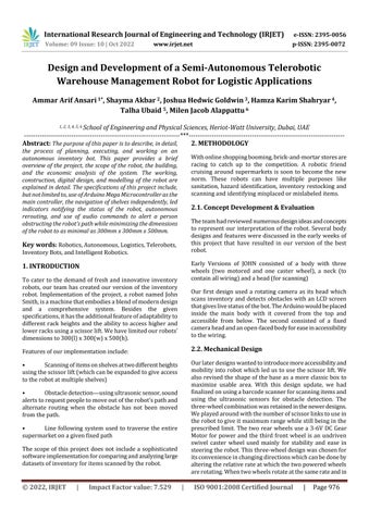
To cater to the demand of fresh and innovative inventory robots, our team has created our version of the inventory robot. Implementation of the project, a robot named John Smith,isamachinethatembodiesablendofmoderndesign and a comprehensive system. Besides the given specifications,ithastheadditionalfeatureofadaptabilityto different rack heights and the ability to access higher and lowerracksusingascissorlift.Wehavelimitedourrobots’ dimensionsto300(l)x300(w)x500(h).
Featuresofourimplementationinclude:
• Scanningofitemsonshelvesattwodifferentheights usingthescissorlift(whichcanbeexpandedtogiveaccess totherobotatmultipleshelves)
• Obstacledetection usingultrasonicsensor,sound alertstorequestpeopletomoveoutoftherobot’spathand alternate routing when the obstacle has not been moved fromthepath.
• Line following system used to traverse the entire supermarketonagivenfixedpath
The scope of this project does not include a sophisticated softwareimplementationforcomparingandanalyzinglarge datasetsofinventoryforitemsscannedbytherobot.
***
Withonlineshoppingbooming,brick-and-mortarstoresare racing to catch up to the competition. A robotic friend cruising around supermarkets is soon to become the new norm. These robots can have multiple purposes like sanitation, hazardidentification, inventory restocking and scanningandidentifyingmisplacedormislabeleditems.
Theteamhadreviewednumerousdesignideasandconcepts to represent our interpretation of the robot. Several body designsandfeatureswerediscussedintheearlyweeksof this project that have resulted in our version of the best robot.
Early Versions of JOHN consisted of a body with three wheels (two motored and one caster wheel), a neck (to containallwiring)andahead(forscanning)
Our first design used a rotating camera as its head which scans inventory and detects obstacles with an LCD screen thatgiveslivestatusofthebot.TheArduinowouldbeplaced inside the main body with it covered from the top and accessible from below. The second consisted of a fixed cameraheadandanopen-facedbodyforeaseinaccessibility tothewiring.
Ourlaterdesignswantedtointroducemoreaccessibilityand mobilityintorobotwhichledustousethescissorlift.We alsorevisedtheshapeofthebaseasamore classicboxto maximize usable area. With this design update, we had finalizedonusingabarcodescannerforscanningitemsand using the ultrasonic sensors for obstacle detection. The three-wheelcombinationwasretainedinthenewerdesigns. Weplayedaroundwiththenumberofscissorlinkstousein therobottogiveitmaximumrangewhilestillbeinginthe prescribed limit. The two rear wheels use a 3-6V DC Gear Motor for power and the third front wheel is an undriven swivel caster wheel used mainly for stability and ease in steeringtherobot.Thisthree-wheeldesignwaschosenfor itsconvenienceinchangingdirectionswhichcanbedoneby alteringtherelativerateatwhichthetwopoweredwheels arerotating.Whentwowheelsrotateatthesamerateandin
2022, IRJET | Impact Factor value: 7.529 | ISO 9001:2008 Certified Journal | Page976

International Research Journal of Engineering and Technology (IRJET) e-ISSN: 2395-0056
thesamedirection,arobotwillcontinuetomovestraight. These two motors are powered through a Motor Driver whichgetsitfroma6-7VDCSource.
Thescissorliftispoweredbyaservomotor.Ourdesignuses atwo-linkliftwithtwosetsofscissorsoneachsideofthe robot,thetwosetsconnectedbytwoperpendicularrods oneatthebaseandoneinthecentre.Theperpendicularrod at the base is connected to the servo motor via a sturdy motor.A180Orotationoftheservomovestheliftfromits lowesttoitshighestposition,thedistancecoveredbeing≈ 20mm. The power for this servo is provided by a 5V DC Source.TheBarcodeScannerisplacedontopofthescissor liftandconnectedtotheArduinoMegainthebasethrough anArduinocompatibleUSBHostShield.
ArduinoMega providesa greatplatformfortheexecution andworkingofthesesensors.Thesensorsweusedare as follows:
Ultrasonic sensor is a device that can detect and measuretheproximityofanobjectintermsofdistance.This deviceusesultrasonicsoundwaveswhichbouncebackfrom the object to find out how far away the object is from the sensor.Theultrasonicsensorconsistsofatransducer,the partofthesensorwhichsendsandreceivesthesound.The difference in time between emission and receiving of the ultrasound is what determines the distance between the objectandthesensor.Hence,theultrasoundalwaysbounces backfromanyobjecttothesensor.[1]
Ourrobotisplacedinanenvironmentwherehuman intervention is possible. Due to this, the robot needs the abilitytodetectthehumansandtakethenecessaryaction rather than clashing with them. For this purpose, we are makinguseoftheultrasonicsensorwhichcandetectifany objectorhumanisinthewayoftherobot.Ourspecifications alsoincludetomaintainaphysicaldistanceof20cmfrom the shelves. The robot could autonomously detect the distancefromtheshelvesusingtheultrasonicsensor.
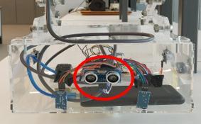
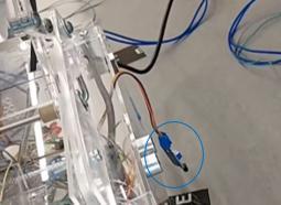
We are making use of 3 ultrasonic sensors. One of themisplacedonfrontsideoftherobot,todetectanyobject or person; one placed on the left side of the robot, to measurethedistancefromtherobot totheshelf;andone placedontherightside(asshowninFig).Thethirdsensoris usedtocheckifthepathisclearwhilsttherobottakesan alternateroute.
Ifthereisanyobjectorhuman(lessthan30cmaway), blockingthepathoftherobot,thesensorinthefront,which alwaysremainsactive,willdetecttheobstacle,andinform theArduinothatthereisanobjectnearby.Whenthisoccurs, the robot comes to a complete stop and gives an audio warningtothepersonusingaPiezobuzzer.Iftheobstacle doesnotmove,therobotwilltakeanalternatepath,which involves going around the obstacle and re-joining the plannedpath.
Oneofthekeyfeaturesofanyautomatedrobotistobeable to receive information from different environments and situations. Sensors are the tools that would interpret this kindofinformationtoeitherhumansormachines.Andour robot,John,iswellequippedwithdiversekindsofsensors forsuchuniquefunctions.Themovementandtasksofour robotisdependentonthefunctionalityofthesensors.The
Infrared sensors or IR sensors is an electric component, used to detect several characteristics by emitting infrared radiation. This sensor is very much like thatofahumanvisiontodetectobstaclesandpaths.[2]
Forthemovement of ourrobot,wehavedecided to usethemethodoflinefollowing.Thismethodinvolvesthe robot following a path placed on the floor or an invisible path involving infrared lines. For this method, the robot needstodetectthelineandmovealongthelineanddetectit simultaneously.ThisispossibleusingtheIRsensors.TheIR
Volume: 09 Issue: 10 | Oct 2022 www.irjet.net p-ISSN: 2395-0072 © 2022, IRJET | Impact Factor value: 7.529 | ISO 9001:2008 Certified Journal | Page977
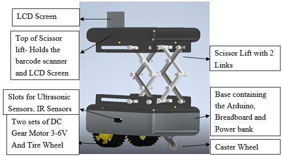
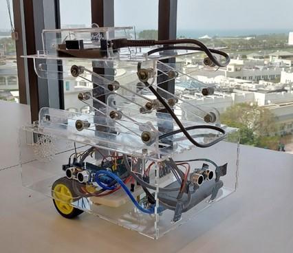
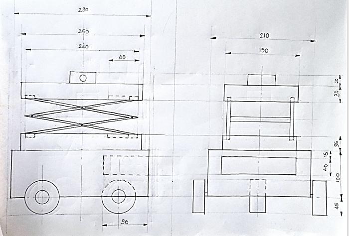 Fig -1: MechanicalDesign
Fig -2: CADModelRendering
Fig -1: MechanicalDesign
Fig -2: CADModelRendering
International Research Journal of Engineering and Technology (IRJET) e-ISSN: 2395-0056
Volume: 09 Issue: 10 | Oct 2022 www.irjet.net p-ISSN: 2395-0072
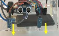
sensorscandetectwhiteorblackduetotheirrecognizable wavelengths.Ourrobotisequippedwith2IRsensorswhich areusedforfollowingtheline.Thesetwosensorsareplaced atthebottomoftherobotandasclosetothegroundsothat the sensors could detect the highest wavelength possible without any errors. The two sensors: left and right, will guidetherobotalongthelinebydetectingthecolorofthe lineandinformingtheArduinotomoveinthedirectionof thedetectedcolorevery10ms.Wehaveequippedtherobot with particularly 2 sensors because of the possible lateral movements, which would involve turning left or right. WhenevertheleftIRsensordetectsahighervalue,therobot turnstowardstheleftandwhentherightIRsensordetectsa highervalue,therobotturnstowardstheright.However,if boththeIRsensorsdetectahighervalue,itwouldmeanthe robotwouldhavetogostraight.
barcode scanner to scan the items on the shelf. We have planned to put different colors near the shelves corresponding to the category of items placed on them. However, only one color would be used in every shelf to trigger the up and down movement of the scissors. Every timethesensordetectstheredcoloronthefloor,therobot would stop, and the scissors would start moving up and down,hencerecognizingthatthereisashelfnearby.Upon movingforward,itwoulddetectanotheruniquecolor,which wouldinformtherobotatwhichshelfitislocated.
However,duetothetechnicalincompatibilityofthe TCS3200 color sensor, we have used an extra IR sensor, placedontheleftsideoftherobot.ThisIRsensoractsasa colorsensor.Onceitdetectsablackmarkplacedonthefloor, itwouldinformtheArduinothatithasreachedashelfand triggertheupwardanddownwardmovementofthescissors andstartscanningtheitemsontheshelf.Onceitreachesthe endoftheshelf,itwoulddetectanotherblackmarkwhich would stop the movement of the scissors and continue to follow the path. The different shades of the black mark is whatwoulddifferentiatetheshelves.
Anyrobotthatwouldworkautonomouslyorwithouthuman interventionneedsaninitialsetupandasetofrulestofollow so that it works according to the specifications desired. Codingthecommandsonaspecificintegrateddevelopment environment (IDE) that is compatible with the Arduino is one of the main necessities for our robot to function properly.Everythingtherobotdoesismainlydependenton the code uploaded on the Arduino. Our code is made and dividedintodifferentmethodsorfunctions,forabstraction, whichwouldreducecomplexityandisunderstoodeasilyby theusers.Themethodsdefinedarethenusedaccordinglyin a loop. This loop would run for every ten milliseconds, executingdifferenttasksaccordingtotheuniqueneedsand scenarios.
Acolorsensorisadevicethatdetectscolor,oritsonly purpose is to detect color. Similar to the working of the ultrasonicsensor,insteadofsoundwaves,thissensoremits its own light and then obtains the reflected light from the object and determines its color. The color sensor module onlyhasfiltersforthecolorsred,green,andblue.
Fortherobottoknowthatithasreachedaparticular shelf, we planned to use the sensor to recognize distinct colors for different shelves, hence, it would be able to autonomouslydetectwhichshelfithasreached.Thissensor was also used to trigger the scissors movement for the
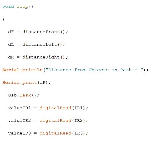
The loop contains parameters that are to be measured duringtheloopinterval.Someofthemincludethedistance measured by the three ultrasonic sensors, namely the distancefromtherobottoanyobstacle(distanceFront),the distancefromtherobottotheshelves(distanceLeft)andthe distance fromthe robot toanyobstaclewhilethe robot is taking an alternate path(distanceRight). The method Usb.Task()isafunctionthatactivatesthebarcodescanner, whichisconnectedtoa
USB host shield that is connected to the Arduino. The remainingthreeparametersaremeasuredbytheIRsensors. These values are read every 10 milliseconds to give an outputofHIGHorLOW.Usingtheseparameters,therobot doesitsbasicfunctionoffollowingthepath.
Toexecutedifferentfunctionsduringdifferentscenarios,we usethe‘if’conditionsthatwoulddefinecertainconditions
International Research Journal of Engineering and Technology (IRJET) e-ISSN: 2395-0056
andexecutetheappropriatemethodsifthoseconditionsare satisfied.
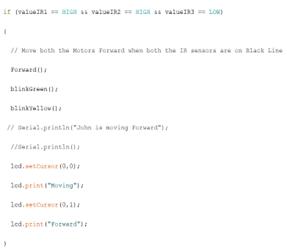
Forexample,ifboththeIRsensorsdetecttheblacklineand third IR sensor does not detect any black marking, this wouldmeanthattherobot neednotscananyshelvesand justmoveforward.Hence,thecodeisdefinedinsuchaway thatwhenboththeIRsensorsdetecttheblackline,itmoves forward,orinotherwords,boththemotorsofthewheels moveforward.Whiledoingso,italsogivesanLEDindication totheusersthattherobotisfollowingtheline.
Orifwetakeanotherexample,ifitinvolvesotherscenarios, suchaswhenthethirdIRsensordetectsablackmarking,it needstotriggertheupwardanddownwardmovementofthe scissorsandgiveanindicationthatisscanningtheitems.Or ifanobstaclewhichis40cmawaycomesinthewayofthe robot,therobotneedstogiveanaudiowarningtotheuser, andthentakeanalternateroute.Theseconditionsarealso definedusingthe‘if’conditionsandexecutesdifferenttasks asshownbelow.
Fig-8: ConditionasIRSensordetectsshelfmark
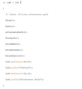
Fig-6: Parametersmeasuredinloop
Fig-9: ConditionsasHC-SR04sensorsdetectsobstacles
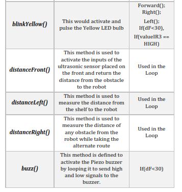
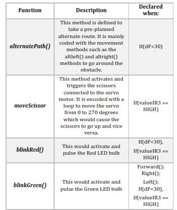
Therearemanymethodsandfunctionsdefinedwithcertain tasksdependingontheinputsofthesensors.Themovement methodsdefinedare:
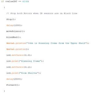
Fig-7: ConditionwhenIRSensorsdetectsline
The motors attached to the main circuit board “Arduino Mega”arenotcompatibletodirectuse,henceaninterfacing integratedcircuit(IC),namely,L298DMotorDriver,isused for giving the DC Motors capability to be controlled using digitalsignalsfromthemainmicrocontroller.ThePWMpins, aka, Pulse Width Modulation pins, modulates, and manipulatesthe widthofa digital squarewaveemitted to controltheon/offstateonanelectroniccomponent,hence making it possible for the components to be controlled digitallyinmultiplevariants i.e.,speed,brightness,torque etc.
Volume: 09 Issue: 10 | Oct 2022 www.irjet.net p-ISSN: 2395-0072 © 2022, IRJET | Impact Factor value: 7.529 | ISO 9001:2008 Certified Journal | Page979
International Research Journal of Engineering and Technology (IRJET) e-ISSN: 2395-0056
Volume: 09 Issue: 10 | Oct 2022 www.irjet.net p-ISSN: 2395-0072
FunctionsdefinedforMotorControl:
Forward(): This method sets the two gear motors (the wheels)tohigh,whichmakesboth wheels move forward and hence, the whole robot would moveforward.
Left(): Thismethodsetstheleftmotortohigh,whichwould only make the left wheel move, which turns the robot towardstheleft.Anothermethod,altLeft,wouldsettheleft wheel to move backward and the right wheel to move forward.Thiswouldalsoresultintherobotturningtowards theleftbutsmoothersincebothmotorsareinvolved.This methodisusedonlyforalternatepath.
Right(): Here, the right motor is set to high, which would only make the right wheel move, which turns the robot towards the right. Similarly, altRight, would set the right wheeltomovebackwardandtheleftwheeltomoveforward whichwouldresultinasmootherrightturn.Thismethodis alsousedforalternatepath.
Stop(): This method sets both the motors to low, which would make both the wheels to stop moving. The robot would not move when this method is declared. Other methodsusedinthecodeareasfollows:
Table 1: MethodsandFunctionsUsedintheAlgorithm
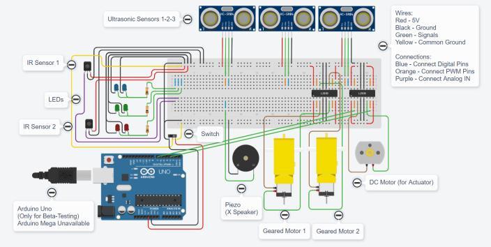
Wemadeourinitialsimulationsandconnectionsusingthe website www.tinkercad.com; a popular website to create circuitsinvolvingtheArduino.Duringtheinitialstagesofour design, we started working with the Arduino UNO, which wasavailableontheonlinetinkercad.Thebasicstructureof ourwiringandcomponentswasdesignedbelow:
However,itwasclearthatwerequiredmorepinsthanthe ArduinoUNOprovided.Thisgaveusthechancetousethe ArduinoMEGA.SincetheArduinoMEGAwasn’tavailableon theonlinesimulation,computersimulationswerenoteasily available.Hence,weevaluatedeachandeverycomponenton therealMEGAinsteadofsimulation.
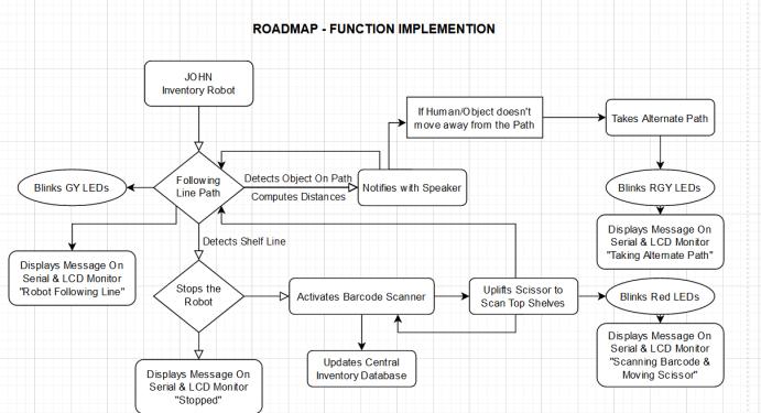
Fig 10: AlgorithmImplementationRoadmap
AfterreceivingtheArduinokits,weconductedaninitialtest byusingasimpleArduinocodefortheDCmotorstorun.The motorsatfirstwererunningatterriblyslowspeedandthis was an issue as these two motors would be supplying the wheelswithpowerthatneedstobeenoughforthewhole bodytomovesmoothly.Asthebodywaspartiallymovingin theabsenceofthescissorlift,wedecidedtotryoutdifferent methodstoincreasethespeedofthemotorsuchaschanging themotordriver,usingadifferentpowerbanksupply,and usingapairofdifferentmotors.Finally,wedecidedtouse thepowersupplyavailableinthelabandseeiftheproblem was with the motor or the supply (power bank) we were using.Afterconductingthetest,wehadfoundoutthatthe motorwasrunningfastenoughwhengivenenoughvoltage fromthevoltagesupplytherefore,wedecidedtouseaDC generator.
Thescissorliftwasacrucialpartofourdesign,wefacedalot of issues at first regarding the scissor lift however found solutions where needed. Our first issue we faced was to
makeitmoveupanddown,weinitiallyusedanactuatorthat waspoweredusinga5Vmotorandhada3-Dprintedcover howeverwhenthescissorliftwaslasercut,theactuatorwas notpowerfulenoughtomakeitmoveupanddownwhenthe topwasadded.We,therefore,decidedtouseanactuatorthat waspoweredbyamotorwithgreatervoltage,greatertorque anditdidthejob.Theotherissuewefacedwiththescissor liftwaswhilegoingupanddownthebasewasnotaligned, andthestructurewasnotstableenough.Tofindasolution to this problem we had first tried to tighten and loosen various bolts however, it did not resolve the problem. A metalrodthatwasconnectedtobothsidesfromthebottom and was free to move back and forth and this helped us stabilizetheliftingprocess.
Laser cutting was a crucial part of our project which had initiallystartedlasercutting,theprocesswasgoingsmooth untilwestartedtoassemblethepartsalreadylasercut,the interlocks between the base and sides were not fitting. At first,wesuspectedourdimensionswereinaccuratehowever after checking the dimensions on our file and comparing themtothepartsalreadylasercut,itwasnottheissue.We then suspected that the software had a calibration issue when connected to the laser printer and after making changes of a few mm on our dimensions we successfully printedthepartsneededwithaperfectfit.
After laser cutting all the parts needed we started to assemble the robot during this process we faced multiple difficultiesandhadtotestoutdifferentwaystotacklethe problemsomeofthedifficultieswehadfacedweredrilling throughsomepartsasacryliccouldbesensitivethereforeit neededtobehandledwithcare,wehadfirstconductedatest on a small portion of acrylic and moved our way into the partsneededtobedrilled. Moreover,foldingacrylicusing heathadtobeassessedfirstbyourteammembersbefore doingitandwehadlearnedafewtipswhiledoingthis.
The goal of the automation system is to do and assess all requiredactivitiesmoreeffectively,reliably,andprecisely than a human worker could. The most essential factor, of course, is to make the system more secure. Our selfcontained sensor-based inventory checking system was created to give our clients with continuous, inventory monitoringandreportingtoacentraldatabasetomanage and maintain the inventory status of the products. Automationisusefulforspeedinguptheflowofinformation andallowingforthemonitoringandcontrolofoperations moreeffectivelyandefficiently.
International Research Journal of Engineering and Technology (IRJET) e-ISSN: 2395-0056
Volume: 09 Issue: 10 | Oct 2022 www.irjet.net p-ISSN: 2395-0072
[1]. Robot Grocery 2022 . Available at: https://www.roboticsbusinessreview.com/retailhospitality/5-robots-grocery-stores-now/
[2]. Carrefour Robots. 2022. Available at: https://www.simberobotics.com/news/carrefour-employsmore-tally-inventory-robots-across-its-stores
[3]. Logiwa Robotics 2022. Available at: https://www.logiwa.com/blog/warehouse-robotics
[4]. MaxBotixInc.2022.UnderstandingHowUltrasonic Sensors Work | MaxBotix Inc.. Available at: https://www.maxbotix.com/articles/how-ultrasonicsensors-work
[5]. WatElectronics.com.2022.IRSensor:Circuit,Types, WorkingPrinciple&ItsApplications.[online]Availableat: https://www.watelectronics.com/ir-sensor/
[6]. Arduino Based Color Detector Available at:https://www.electronicshub.org/arduino-based-colordetector/
2022, IRJET | Impact Factor value: 7.529 | ISO 9001:2008 Certified Journal |