International Research Journal of Engineering and Technology (IRJET)
e-ISSN: 2395-0056
Volume: 09 Issue: 10 | Oct 2022
p-ISSN: 2395-0072
www.irjet.net
Pressure drop analysis of flow through pin fin channel Ayush Lal Michigan Technological University, USA ---------------------------------------------------------------------***---------------------------------------------------------------------
Abstract – A traction inverter is an equipment in all electric or hybrid vehicles, which converts DC current from the battery to AC which in turns drives an electric motor to propel the vehicle. During its usage, they tend to generate a large amount of heat (1). Pressure drop analysis of inverters becomes important to regulate the amount of load which is faced by the electric pump pumping coolant to the inverter.
This paper deals with the pressure drop analysis of a pin fin coolant channel using ethylene glycol 50/50 as the coolant. Three different designs are considered with pin fin diameters of 4mm, 6mm and 8mm with temperature varying from -17.8C to 80C. The study will be useful to analyze the behavior of ethylene glycol 50/50 for design of coolant system for automotive inverter of any electric vehicle.
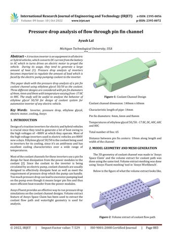
Coolant channel dimension: 140mm x 60mm
Key Words: Inverter, pressure drop, ethylene glycol,
Characteristic length of pipe: 14mm
Figure-1: Coolant Channel Design
electric motor, cooling, Ansys
Pin fin diameters: 4mm, 6mm and 8amm
1. INTRODUCTION
Temperatures of ethylene glycol 50/50: -17.8C, 0C, 40C, 60C and 80C
Design of a traction inverters for electric and hybrid vehicles is crucial since they tend to generate a lot of heat owing to the high voltages of ~800V at which they operate. Most of the high voltage inverters used in electric vehicles are 800V now a days. Ethylene glycol 50/50 is the coolant being used in inverters for its cooling, since it’s an antifreeze and has excellent cooling characteristics over a wide range of temperatures.
Total number of fins: 65 Distance between pin fin centers: 10mm along length and width of the channel
2. MODEL GEOMETRY AND MESH GENERATION The 3D geometry of coolant channel was made in ‘Ansys Space Claim’ and the volume extract for coolant path was done using the same tool. Volume extract meshing was done using ‘Ansys Fluent meshing’ tool in ‘Ansys Workbench’.
Most of the coolant channels for these inverters use a pin fin design for heat dissipation from the power modules to the coolant [2]. Since the coolant to the inverter is being circulated by an electric pump, coolant channels are usually designed to effectively dissipate heat as well as meet the requirement of pressure drop which the pump can handle. Too much pressure drop can lead to excessive pumping load on the pump even though it means larger pin fins and thus more efficient heat transfer from the power modules.
Below is the figure of what the volume extract looks like,
Ansys Fluent provides an effective way to run pressure drop simulations on the coolant channel designs. Volume extract feature of Ansys Space Claim has been used to extract the coolant flow path and watertight geometry is used for analysis.
Figure-2: Volume extract of coolant flow path
© 2022, IRJET
|
Impact Factor value: 7.529
|
ISO 9001:2008 Certified Journal
|
Page 883