International Research Journal of Engineering and Technology (IRJET) e-ISSN: 2395-0056

Volume: 09 Issue: 10 | Oct 2022 www.irjet.net p-ISSN: 2395-0072

International Research Journal of Engineering and Technology (IRJET) e-ISSN: 2395-0056
Volume: 09 Issue: 10 | Oct 2022 www.irjet.net p-ISSN: 2395-0072
P SHENBAGAVALLI1, A GOKUL RAJAN2, B PRADESH KUMAR3 , R GNANAPRAKASH4
1Centre Head, Dept. of Mechanical Engineering, CADD CENTRE, Thuraiyur, Tamilnadu. 2, 3, 4 UG Student, Dept. of Mechanical Engineering, CADD CENTRE, Thuraiyur, Tamilnadu. ***
Abstract - This paper has developed a three‐dimensional finite element model to simulate dynamicallytheProjectionWeldingprocessofsteelsheets.The numerical simulation was conducted using a non‐linear transient thermal analysis by changing the welding parameters. A moving Gaussian distributed heat source is implemented. All major physical phenomena associated with the Projection Welding process, such as thermal conduction and convection heat losses, are considered in the model development. The developed model can calculate the temperaturefieldandpredicttheweldgeometryprofileduring the welding process. The model employs the conjugate heat transfer analysis technique toavoid estimating a value for the heat transfer coefficient that arises with conventional heat transferanalysis.WearegoingtofixthenutontheplateUsing projection welding. we are using study state thermal analysis. Tofindthetemperaturedistributiononthenutandplateusing ANSYS 2022R2.
Key Words: Projection Welding, Finite Element Analysis, Temperature, Heat flex, Mesh…
Welding is a common method of joining metals. A method of joining two or more metals together using temperatureatthemolecularlevel.Twopiecesofmetalcan be joined using molten filler metal at the point of joining. Someexternalweldingcanbedonewithoutfillermetalusing pressureandheat.Weldingiswidelyusedintheconstruction andautomotiveindustry.Theweldingprocessisveryeasyto understand and learn its basic technique. Gas metal arc (MIG), gas tungsten arc (TIG), carbon arc, andoxyhydrogengasweldingarethemostcommontypesofwelding used in industries. Projection welding is a type of electric projection welding. Forms a connection between suitable electrodesataninternalizedpointintheworkspaceunder pressure.Unlikeothertypesofwelding,projectionwelding usesheatandpressuretobondthetwometalstogetherusing a lump of metal. The heat used is generated by electrical resistance.Usedintheelectronicsandautomotiveindustry. Projectionweldingvariesdependingontheweldingdesign, force,power,time,type,andthicknessofthematerialbeing welded.
Inourproject,wedesigned3Dmodelsofthetooland the weld plates using AUTOCAD software. AUTOCAD is a familyorsuiteofdesignsoftwaresupportingproductdesign for discrete manufacturers and is developed by Autodesk. Autodeskisascalable,interoperablesuiteofproductdesign softwarethatdeliversfasttimetovalue.Ithelpsteamscreate, analyze, view, and leverage product designs downstream utilizing2DCAD,3DCAD,andparametric&directmodeling. AUTOCAD provides the broadest range of powerful yet flexible 3D CAD capabilities to accelerate the product developmentprocess.Byautomatingtaskssuchascreating engineering drawings, we can avoid errors and save significanttime.
Thesoftwarealsoletsusanalyze,createrenderingsand animations,andoptimizeproductivityacrossafullrangeof othermechanicaldesigntasks,includingcheckinghowwell ourdesignconformstobestpractices.AUTOCADParametric enables us to design higher-quality products faster and allows us to communicate more efficiently with manufacturing,andsuppliers.
In our present work, we considered two similar metals STEELperformprojectionweldingonthem,Forthispurpose, wecreated3Dmodelsoftheweldplates,thenutofboththe metalstobejoined,andthetoolprofileswithwhichthestir welding is performed, with the following specifications
Lengthoftheplate=100mm
Widthoftheplate=30mm
Diameterofthenut=5mm Thickness=3.5mm
International Research Journal of Engineering and Technology (IRJET) e-ISSN: 2395-0056
Volume: 09 Issue: 10 | Oct 2022 www.irjet.net p-ISSN: 2395-0072
Height=10mm
Weldingprojectionheight=0.6mm
Weldingprojectionradius=0.7mm
Now,itistimetoknowabouttheadvantages.So,let's discusssomeofthemostimportantbenefitsofthiswelding technique:
Asabovestated,thisweldingrequiresaverysmall supplyofcurrent,andthus,itsaveselectricityusage.
So, less electricity requirement and a longer electrodelifearethetwomostprominentbenefitsof thisweldingprocess
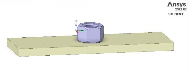
Fig -2:Plateandnut(stage1)
Whiledoingspotweldingthereisalimitationonthe thicknessofthemetalthathastobewelded.But inthiswelding,almostmetalsofallthicknessesare welded.
Itcanbeusedeffectivelyforweldingjointsthatare incomplicatedlocations.
Theheatbalanceisanimportantpartofanywelding processandthisweldinggivesagoodheatbalance whilewelding.
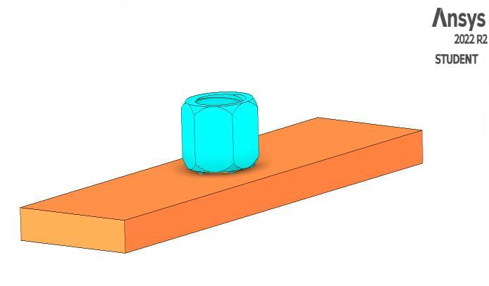
Fig -3: Plateandnut(stage2)
Thisweldingprocessdoesnotapplytosometypes ofcoppersandbrasses.
Projectionformationisaquitecomplicatedprocess andittakestimetoformtheprojections.Itisvery difficulttoformasphericalprojectionandaskilled personisrequiredtoformsuchprojections.While making those projections, the height of the projectionhastobemaintainedproperly.
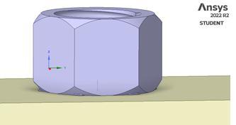
Fig -4:Plateandnut(stage3)
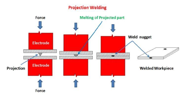
Asperthedefinition,differentprojectionsareformedin thisweldingtechnique.Here,themetalpiecesthataretobe joined are kept in between the two electrodes. A larger pressure force is applied to the electrodes. As current is passedthroughthesystem,heatformationtakesplacedueto the internal resistance of the metal workpieces. One point that you must note down here, is that the heat generation takes place due to the internal resistance of the metal workpieces rather than an electric arc. Those projections concentrate the heat. As the pressure applied to the electrodes increases, this projection collapses and the formation of the fused weld nugget takes place. Thus, a qualityweldisformed.
This process does not apply to all types of workpieces. The composition of the metal workpieceshastobeconsideredwhilethisprocess andithassomelimitations.
As Projection welding is mostly used for mass production.Ithasmanyapplicationssuchas:
Theautomobileindustryusesprojectionweldingto averylargeextent.Thisweldingprocessisalsoused forfancoversandhollowmetaldoors.Itisalsoused for producing compressor parts and for semiconductors.
Haveyouheardaboutdiamondsegmentwelding?In diamondsegmentwelding,projectionweldingfinds itsapplications.
International Research Journal of Engineering and Technology (IRJET) e-ISSN: 2395-0056
Volume: 09 Issue: 10 | Oct 2022 www.irjet.net p-ISSN: 2395-0072
So, this is the exact working principle as well as the advantages, disadvantages, and applications of projection welding. We are sure that you get the exact details of the projectionwelding.
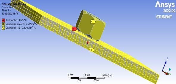
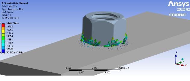
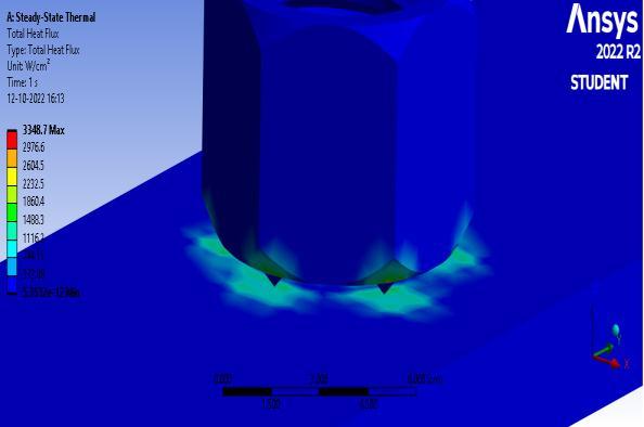
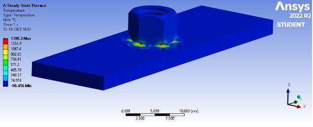
Fig -5:Meshmodal
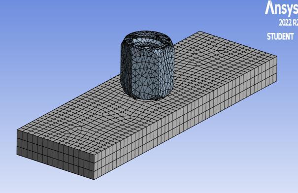
Fig -6:Boundarycondition
Fromtheabovefigure,thetotalheatfluxontheweld platesisobtained.Thebluecolorindicatestheareaoflowest heat flux which is 5.3512e-12W/mm2 and the red color indicates the area of maximum heat flux which is 3348.7 W/mm2. The intermediate values of total heat flux on the weld plates are obtained in the middle range indicated by differentcolorsinthegraph.
Fromtheabovefigure,thetemperaturedistributionon theweldplatesisobtainedinstage1.Thebluecolorindicates thelowesttemperaturezonewhichis90.546oCandthered color,whichwasbelowthetool,ieatthetooltipindicatesthe maximum temperature zone which is 1396 C. The intermediatetemperaturesareobtainedinthemiddlerange indicatedbydifferentcolorsinthegraph.
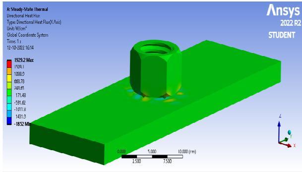
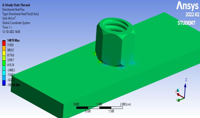
Fig -9: DirectionalHeatflex
Fig -10:vectoronplateandnutheatflex
Table -1: AnalysisResultStage1
Results Minimum Maximum Units Times(s)
Temperature -90.456 1398.3 °C 1. TotalHeat Flux 5.3512e012 3348.7 W/cm² 1.
Directional HeatFlux -1852. 1929.2 W/cm 1.
International Research Journal of Engineering and Technology (IRJET) e-ISSN: 2395-0056
Volume: 09 Issue: 10 | Oct 2022 www.irjet.net p-ISSN: 2395-0072
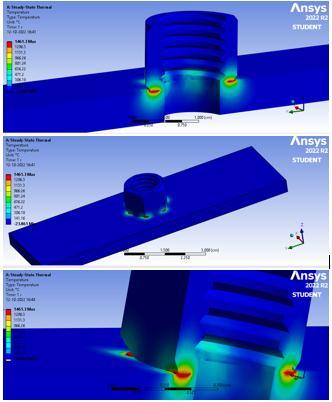
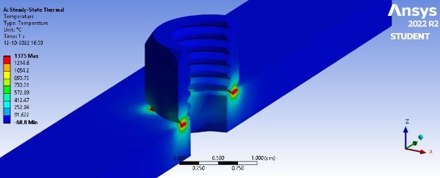
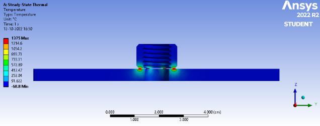
Fromtheabovefigure,thetemperaturedistributionon theweldplatesisobtainedinstage2.Thebluecolorindicates the lowest temperature zone which is 68.8oC and the red color,whichwasbelowthetool,ieatthetooltipindicatesthe maximum temperature zone which is 1375 C. The intermediatetemperaturesareobtainedinthemiddlerange indicatedbydifferentcolorsinthegraph.
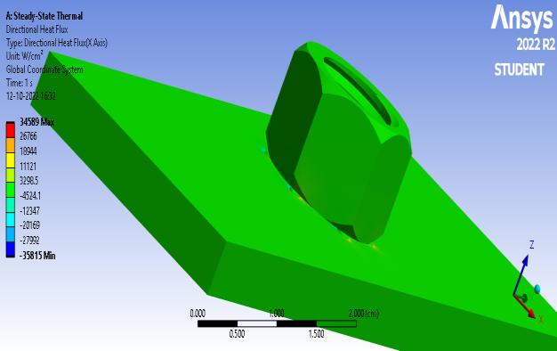
Fig -14:DirectionalHeatflex
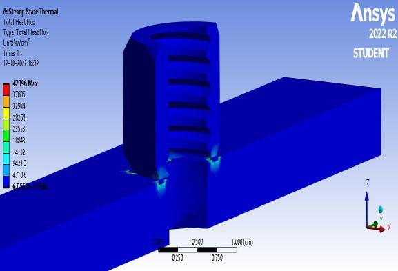
Fromtheabovefigure,thetotalheatfluxontheweld platesisobtained.Thebluecolorindicatestheareaoflowest heat flux which is 6.0561e-11W/mm2 and the red color indicates the area of maximum heat flux which is 42396 W/mm2. The intermediate values of total heat flux on the weld plates are obtained in the middle range indicated by differentcolorsinthefigure.
Temperature -68.8 1375 °C 1. TotalHeatFlux 6.0561e-011 42396 W/cm² 1. DirectionalHeat Flux -35815 34589 W/cm 1.
Fig -15:Temperaturedistribution
International Research Journal of Engineering and Technology (IRJET) e-ISSN: 2395-0056
Volume: 09 Issue: 10 | Oct 2022 www.irjet.net p-ISSN: 2395-0072
Fromtheabovefigure,thetemperaturedistributionon theweldplatesisobtainedinstage3.Thebluecolorindicates thelowesttemperaturezonewhichis23.861oCandthered color,whichwasbelowthetool,ieatthetooltipindicatesthe maximum temperature zone which is 1461 C. The intermediatetemperaturesareobtainedinthemiddlerange indicatedbydifferentcolorsinthegraph.
3Dmodelingoftheworkplatesandweldtooltipsare producedandimportedsuccessfullyforjoiningtwosimilar metalssteel. FiniteElementAnalysisisdoneonthenutand plate. FromtheThermalAnalysistemperaturedistribution, and thermal flux, are obtained. From the results, it is observed that thermal flux and temperature are more in stage 3 than the stage 2.The temperature produced is sufficientforobtainingthemeltingpointsoftheplates.From FEAanalysisitisevidentthatstage3ispreferablethestage 2,inprojectionwelding.Notremovetheburronprojection welding. Not remove the burr on projection welding. 95% projectionweldingsuccessfullyfixedonplateandnut.
[1] Zhang, W., Kim, C. L., and DebRoy, T. 2004. Journal of AppliedPhysics,95(9):5210–5219.
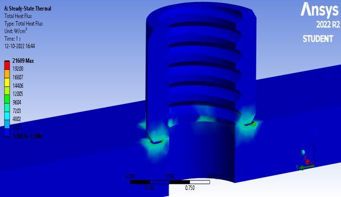
Fromtheabovefigure,thetotalheatfluxontheweld platesisobtained.Thebluecolorindicatestheareaoflowest heat flux which is 3.3865e-11W/mm2 and the red color indicates the area of maximum heat flux which is 21609 W/mm2. The intermediate values of total heat flux on the weld plates are obtained in the middle range indicated by differentcolorsinthegraph.
[2] Rai, R., and DebRoy, T. 2006. Journal of Physics, D: AppliedPhysics,39(6):1257–66.
[3] Yang,Z.,Sista,S.,Elmer,J.W.,andDeRoy,T.2000.Acta Materialia,48(20)4813–4825.
[4] Mishra,S.,andDebRoy,T.2004.ActaMaterialia,52(5): 1183–1192.
[5] Sista, S., and DebRoy, T. Metallurgical and Materials Transactions,B,32(6):1195–1201.
[6] Mishra, S., and DebRoy, T. 2004. Journal of Physics D: AppliedPhysics,37:2191–2196.
[7] Elmer, J. W., Palmer, T. A., Zhang, W., Wood, B., and DebRoy,T.2003.ActaMaterialia,51(12):3333–3349.
[8] Zhang,W.,Elmer,J.W.,andDebRoy,T.2002.Materials ScienceandEngineeringA,333(1-2):320–335.
Fig -17:DirectionalHeatflex
Table -3: AnalysisResultStage3
Results Minimum Maximum Units Times(s)
Temperature -23.861 1461.3 °C 1. TotalHeat Flux 3.3865e011 21609 W/cm² 1.
Directional HeatFlux -11100 14819 W/cm 1.
Similarly, the Thermal Analysis was performed for both roundandsquaretooltipsattraversespeedsof60mm/min and80mm/min.
[9] Mundra,K.,DebRoy,T.,Babu,S.S.,andDavid,S.A.1997. WeldingJournal,76(4):163-sto171-s.
[10] Hong,T.,Pitscheneder,W.,andDebRoy,T.1998.Science andTechnologyofWelding.
Assistant professor, Centre Head, Dept. of Mechanical Engineering, CADD CENTRE, Thuraiyur, Tamilnadu.

International Research Journal of Engineering and Technology (IRJET) e-ISSN: 2395-0056
Volume: 09 Issue: 10 | Oct 2022 www.irjet.net p-ISSN: 2395-0072
UG Student, Dept. of Mechanical Engineering, CADD CENTRE, Thuraiyur,Tamilnadu.
UG Student, Dept. of Mechanical Engineering, CADD CENTRE, Thuraiyur,Tamilnadu.
UG Student, Dept. of Mechanical Engineering, CADD CENTRE, Thuraiyur,Tamilnadu.


2022, IRJET | Impact Factor value: 7.529 | ISO 9001:2008 Certified Journal |