International Research Journal of Engineering and Technology (IRJET) e-ISSN: 2395-0056

Volume: 09 Issue: 10 | Oct 2022 www.irjet.net p-ISSN: 2395-0072
International Research Journal of Engineering and Technology (IRJET) e-ISSN: 2395-0056
Volume: 09 Issue: 10 | Oct 2022 www.irjet.net p-ISSN: 2395-0072
1 M.Tech Scholar, Dept. of Civil Engineering, Shri Rawatpura Sarkar University, Raipur
2 Assistant Professor, Dept. of Civil Engineering, Shri Rawatpura Sarkar University, Raipur
3 Assistant Professor, Dept. of Civil Engineering, Shri Rawatpura Sarkar University, Raipur
4 Assistant Professor, Dept. of Civil Engineering, RSR Rungta College of Engineering and Technology, Bhilai ***
Abstract - Current work has been completed to analyze the structural analysis of tall structures using composite profiles mixed with RCC beams and panels. In this study, a model of a 10 storey ground floor truss structure subjected to Zone V nonlinear dynamic loads is used according to IS 1893-2016 from the ETABS software package. Two similar models were constructed with different column types, RCC and CFST columns, and similar loading conditions were applied. These two models were decomposed and the results obtained were analyzed from a structural design point of view based on the following parameters
Key Words: Non linear, structure, lateral forces, composite, columns, displacement, optimization
AlthoughIndiaisadevelopingcountry,steelconsumptionin the Indian construction sector is much lower than other developedcountries inthe world. Due to huge population growth,concentrationofdevelopmentinperi-urbanareas andlimitedlandarea,urbanpopulationdensityisincreasing daybyday.Increasedpopulationdensityhasincreasedthe demandforskyscrapers.Inhigh-risebuildings,thevertical gravity of columns dominates the design of the building structure,asloadsaccumulateonallfloors.
Earthquakes are devastating events and, unlike other disasterssuchasfloods,peopleareabletoevacuatetosafer locationsalongtheselines,resultinginenormouslossoflife andproperty.increase.Subsequentplanningofstructures fortheseseismicloadsisthemostimportantpossibleoption. Each incident provided important data for improving planning and development exercises in this manner to protectthestructure'soccupants.Thissectionincludescodebased methodologies for seismic surveys, structural instructionconcepts,andcurrentsurveyobjectives.
Moststructuralseismicsurveysarebasedonlateralforces assumedto correspond to truestacking.Thefundamental shear,whichisthetotal uniformforceonthestructure, is registeredbasedonthemassofthestructureandthecritical timeofvibration,takingintoaccountthemodeshapes.Base shearisusedalongtheheightofthestructure,asislateral force, as indicated in the code conditions. This system is
typicallyconventionalforlowtomediumheightstructures withcommonconfigurations.
Compositecolumnsarethecompressionelementwhich constitutes of concrete encased steel section or concrete filledsteeltubes.Concretesteelcompositecolumnsarethe combination of concrete and steel hence uses both the materials for their advantages. Concrete steel composite columns based on the material inside and outside may be classifiedinfollowingcategories:–
Concrete-filled tubes: Concrete-filled hollow rectangular or round steel tubes are called concrete-filledcompositecolumns.
Fully Encased Composite Column: A section of rebar covered with a plain/reinforced concrete jacketiscalledafullyencasedconcretecomposite column.
Partially Encased Composite Column: Partially Encased Reinforced Concrete Section, i. H. Those withtwoormoresides(butnotallsides)arecalled partiallycoatedconcretecompositecolumns.
Murtuza S. Aainawala (June 2016) Through the ETABS2015 programming, he evaluates and reflects historical seismic performance of G+15 consisting of RCC and compositestructures.Bothsteel-solidcompositestructures with concrete-filled steel pipes and RCC structures had delicatefloorsneartheground.,astrategywithequalstatic and reactive regions is used. Floor lift, displacement, selfweight,torsionandsheardriveareconsideredasparameters. at which point the analyzed composite structure shows a morefavorabledesignthantheRCC.
Shakhet. al, (2013): They studied a comparison of the structural behavior of his R.C.C. Composite structure of skyscrapers. To do this, a model of his G+15 projectile in seismic zone IV was created using structural analysis and designsoftware(STADDPRO).Awindloadwithavelocityof 39m/swasapplied.
International Research Journal of Engineering and Technology (IRJET) e-ISSN: 2395-0056
Volume: 09 Issue: 10 | Oct 2022 www.irjet.net p-ISSN: 2395-0072
Desire. Al, (2013): This work seeks to study the seismic performanceofcompositesoftslugcolumns.Fourdifferent models were prepared and their performance was investigated using Stad Pro software. In the -1 model, the floorheightofthebuildingwaskeptconstant,butinthe-2 model,onlythecolumnsonthefirstfloorwerereplacedwith compositecolumns.Inmodel3thefirstfloorandfirstfloor columns were replaced with composite columns, and in model4theheightofthefirstfloorwaschangedto4m.
Soni et al. Al. (2010): Floorsandhisfivefloors,3Dframes during seismic force analysis using Stad Pro software. His threedifferentframetypesareconsidered:RCCframewith RCCplate,secondsteelframewithsteelplateandthirdsteel beam with RCC column and plate. The bearing reaction forces,bearingmomentsandnodaldisplacementsofRCCand steelwerecomparedformoderatesoilsinSeismicZone-III.
Bayerette. al. (2010): The object of consideration is compositestructures.Forthisreason,severalresearchposts havebeenstructuredandestablished.Segmentsrequirealot oftrialanderrortocreatenewgadgetpartswithdifferent constructionmaterials.Theresearchsitewasplannedwith theadvancedgraphicsprogramCAxSiemensNX7.
Structural analysis and design software extended three dimensionalanalysisofbuildingsystems(ETABS)isusedto carry out the analysis of frame with RCC structure and structure with composite columns. The flow diagram of modelingandanalysisofbuildingstructureframeonetabs willbeasbelow-
1. Selectaplanofcommercial/residentialhighrise building.
2. Selectcolumnpositionsontheplan
3. Planbeamlayoutforeachfloorforsettingupgrid lines.
4. Tostartmodelingonetabsselectbaseunitsand designstandards.
5. Setup grid lines for the modeling and define storeylevels
6. Definesectionpropertiesincludingmaterial
7. Drawstructuralobjectslikecolumn,beam,slab& openings.
8. Assignpropertiestodrawnstructuralobjects.
9. Defineloadpatterns,assignloadanddefineload combinations
10. CheckModel,Runanalysis,DesignandGenerate Report.
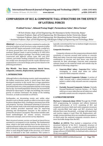
Tocarryouttheanalyticalworkbuildingstructurehaving five grids in X direction at 7.0 mt. equal distance and five gridsinYdirectionat7.0mt.equaldistanceareconsidered asshowninfigurebelow-
Fig-1: GridLinesoftheBuildingStructure
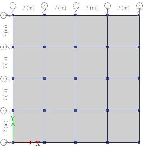
Tocreateamodelofthreedimensionalbuildingstructures inETABSSoftwarefollowingassumptionsareconsideredTable -1: DataforModelingofBuildingFrameStructure 1 NumberofStories G+10+mumty 2 Heightofstiltfloor 3.2mt.
Heightofupperstories 3.2mt.
Depthoffoundation -2.0mt
GradeofconcreteforRCCBeam& Slab M-25
GradeofconcreteforColumns M-25
Steelusedforlongitudinal reinforcement HYSD500
Steelusedforlateral reinforcement HYSD415
SteelSections Fe345
Masonry Infillbrick
SeismicZone Zone-V
International Research Journal of Engineering and Technology (IRJET) e-ISSN: 2395-0056 Volume: 09 Issue: 10 | Oct 2022 www.irjet.net p-ISSN: 2395-0072
Table


International Research Journal of Engineering and Technology (IRJET) e-ISSN: 2395-0056
Volume: 09 Issue: 10 | Oct 2022 www.irjet.net p-ISSN: 2395-0072
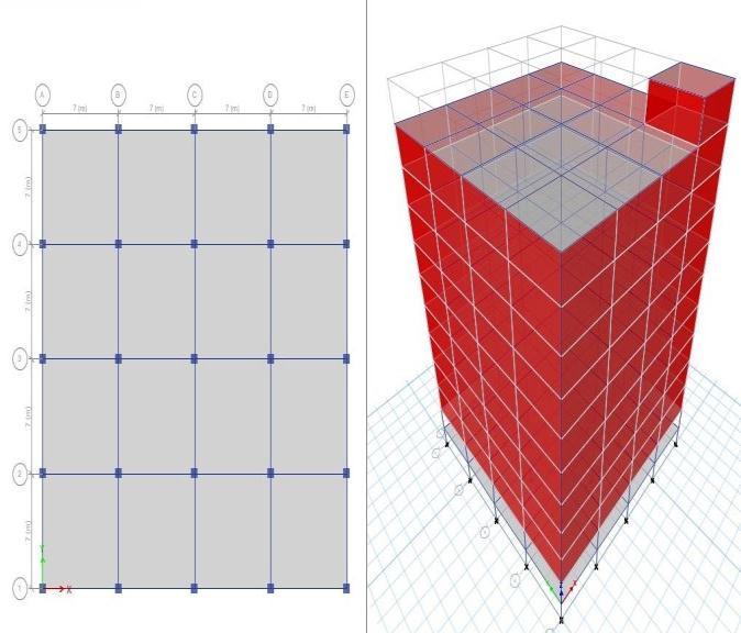
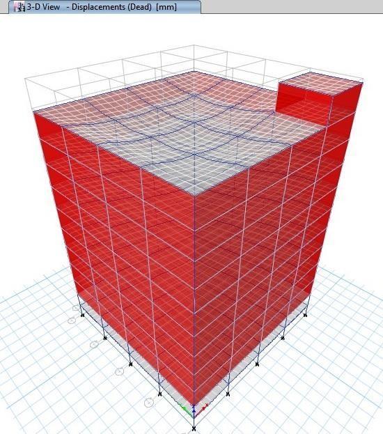
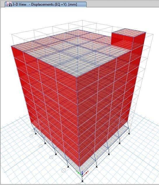
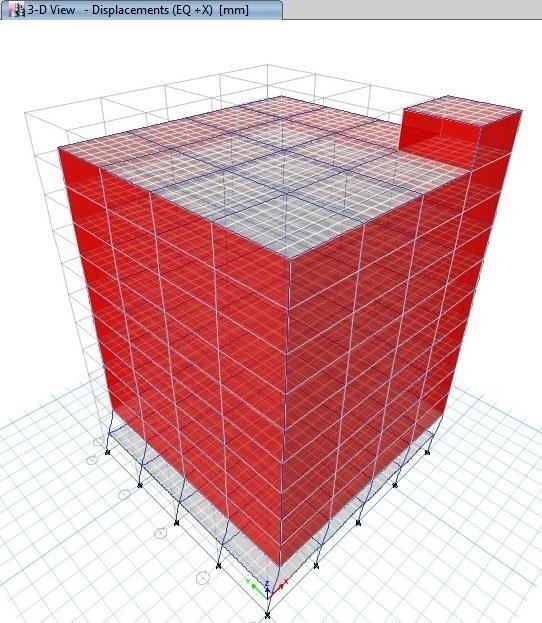
Fig -1: DisplacementDuetoEQ+XSeismicLoad(RCC)


advantage of these possible outcomes, it is important to intentionallycreateacompositestructurethatlookslikereal cement. Inthepast,whendesigningstructures,decisions weregenerallymadebetweensolidstructuresandcraftsman structures. In any case, the disappointment of numerous high- and low-rise RCCs. In addition, seismic masonry structureshaveforcedstructuraldesignerstoseekselective techniquesfordevelopment.Theuseofcompositeorhybrid materials is very attractive due to the huge potential to improveoverallexecutionthroughrathermodestassembly changes and engineering innovations. In India, many consultingarchitectsDue tothe noveltyandcomplexityin research and design, we are reluctant to allow the use of bondedsteelbulkconstruction.However,thispapershows that the solid steel framework properly placed and assembledatthistimeisanincrediblyconservativestructure with the qualities of high strength, rapid construction and better seismic performance Interconnection planning for high-risestructuresisrapidly improvingintheregionand shouldbekeptinmind.ThisisrelativelynewinIndiaandthe equivalentstructurecodeshavenotbeenupdated.Officially, multi-layeredstructuresinIndiaweredevelopedwithR.C.C. Circled Structure or Steel Confined Structure, but more recentlypatternstowardscompositestructureshavebegun anddeveloped.Inthedevelopmentofcompositematerials, twodissimilarmaterialscanbeintegratedbyusingshallow depthheadedstudsat theinterface,resultinginsignificant material cost savings. The heat build-up (coefficient of thermal expansion) of both cement and steel are nearly identical. Thus, different warm concerns in different temperatureregionsarenotaccepted.
1)CompositeBeamDefinitionAsolidsteel compositebeam consistsofasteelbeamstrungwithsolidplatesreinforced withchemicalanchors.Combinedactivityreducesthedepth of the jet. The movable steel segments themselves are sometimes found to be sufficient for construction, and the designedstanchionsareusuallypointless.Compositebeams can also be constructed using profiled sheets with solid facingsor cast orprefabricatedreinforcedsolidplates.
Cement behavior is surprisingly unpredictable and many subtleties are not understood. Interestingly, constructive buildings require basic but solid material laws. Further developmentrelyingontrialtestinghasbeenshowntobe moderate.Advancednumericaltechniquesprovideamazing additionaltools.Compositepropertiesandprocessescanbe decomposedusingarestrictedcomponentstrategy.Totake
2)DefinitionofCompositeColumn Asteel-masscomposite segmentisexpectedtobeacompressionsectionwherethe steelcompositionisinthestructuralsteelregion.Thereare threetypesofcompositesegmentsused:concrete-enclosed sections, concrete-filled sections, and impacted sections. Legacycodeimplicitlymakesmethodattemptstosatisfy all threegoals. A.Negligibledamageduetotremorsofaone-off earthquakewitharecurrenceperiodofabout50years.This canbeachievedbyprovidingelasticstructuralresponseand limiting tier displacement to minimize damage to nonstructural components such as cladding and interior walls. B. Prevention of collapse in the largest required earthquake that may occur at the site. Such earthquakes occur with a recurrence period of about 2500 years. The requirement for inelastic deformation is less than the deformability,roughlyaccountingforthelossofstiffnessand
International Research Journal of Engineering and Technology (IRJET) e-ISSN: 2395-0056
Volume: 09 Issue: 10 | Oct 2022 www.irjet.net p-ISSN: 2395-0072
strengthduetogravitationalloading,secondaryeffects,and cyclicloading.Additionally,thebulletdeformationissmall enough to prevent catastrophic damage to nonstructural members.Deformationisakeyparameterinperformancebasedseismicdesign,notforceormagnitude.variantshecan be divided into three categories. a. total construction movement. Driftingandotherinternaldeformationsofthe BC story. c. Inelastic deformation of parts and elements. Thesemotionsarecausedbyrigidbodydisplacementsand sheardeformations.
CriticalIssues:
High foundation overturning moment and foundation design.
Highrequirementsforfoundationshearcapacity.
Highgravitationalstressreducesusablefloorspaceand increasescomponentcross-sectionalarea.
Ductility development of basic elements under high compressivestress.
Lateralaccelerationandstorydriftcontrols.
Damagecontrolthatallowsrepairs.
Ensuring ductile energy dissipation mechanism and avoidingbrittlefracture
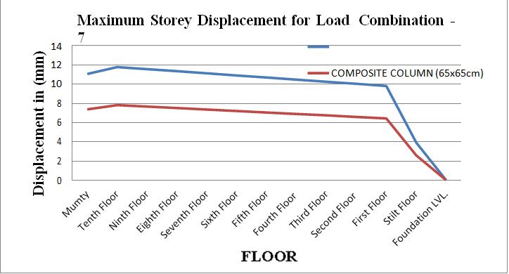
The maximum storey displacements
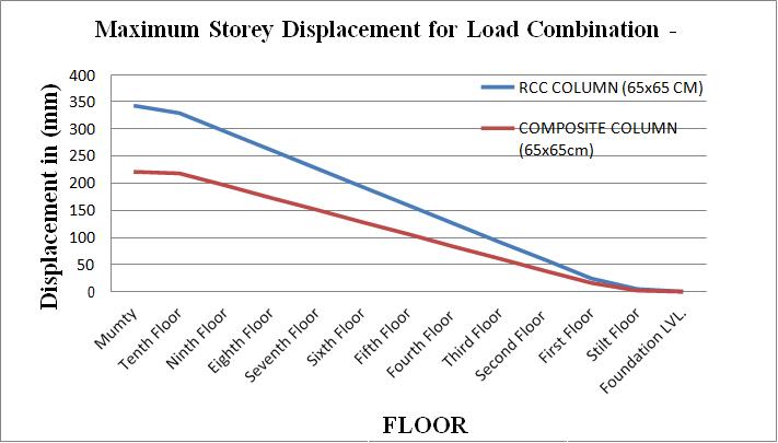
Chart -2:MaximumStoreyDisplacementforLoad Combination-7
DISCUSSION: The maximum floor displacement of the frame withRCC columns is 49% to 55% higher than with composite columns.However, if the cross-sectional size of thecompositecolumnisreducedtotheminimumrequired size,i.e.450x450mmforH.currentmodel,themaximum floordisplacementoftheRCCframewillbereducedby6% to12%.
The Storey shear
Chart -3:StoreyShearforLoadCombination-2
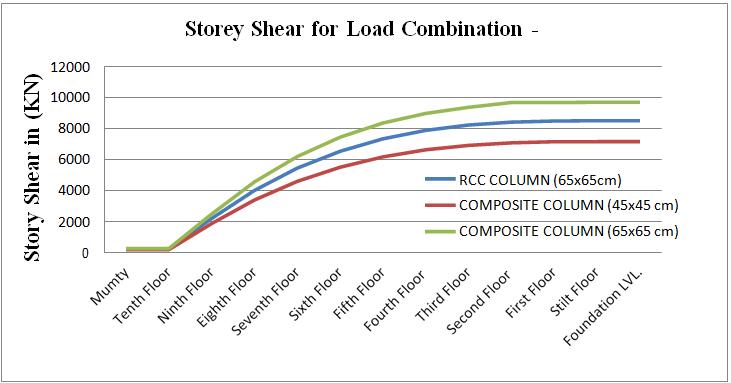
Chart -1:MaximumStoreyDisplacementforLoad
Combination-1
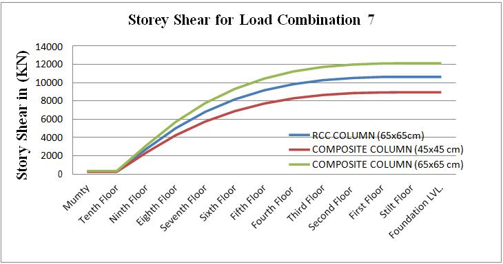
Chart -4:StoreyShearforLoadCombination-7
DISCUSSION:MaximumStoreyshearforframewithRCC columns(65x65CM)is17%to19%higherthantheframe with composite columns (45x45cm). Storey shear in
2022, IRJET | Impact Factor value: 7.529 | ISO 9001:2008 Certified Journal | Page785
International Research Journal of Engineering and Technology (IRJET) e-ISSN: 2395-0056
composite columns are less due to reduced weight of structurewithcompositecolumns.
The Overturning Moment
Chart -5:OverturningMomentforLoadCombination-2
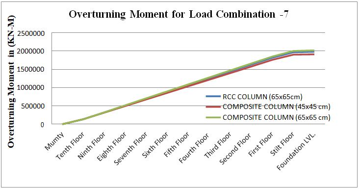
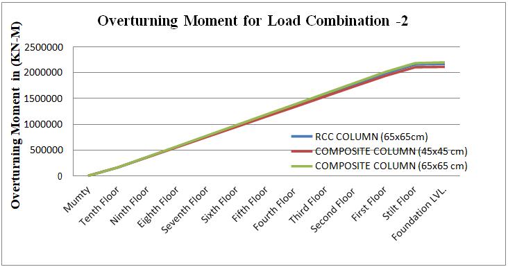
DISCUSSION: Overturning Moment in Frame with composite columns of size 45x45 cm is marginally lower thanRCCcolumnsofsize65x65cmduetoreducedweight.
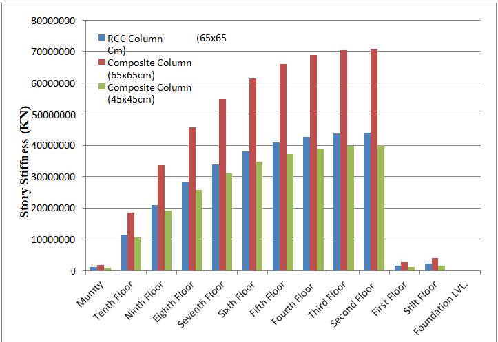
DISCUSSION:StoreyStiffnessinRCCcolumnsofSize65x65 CMis8%to26%higherthanthecompositecolumnsofsize 45x45CM.
AfteranalyzingframeswithRCCcolumnsandframeswith composites and examining the results obtained, the followingconclusionscanbedrawn:
1. Thismodelrequiresasegmentareaof650x650mmin RCC,butwhenplanningthesamemodelincomposite segments,thesegmentsizewasreducedto450x450 mm.
2. ThemaximumfloordisplacementoftheRCCsegmentis 49%to55%higherthanthatofthecompositesegment withthesamearea size.Thespacesizerequiredfora compound segment decreases as the segment size decreases.Themostextremebulletdisplacementsofthe compositesegmentare6%to12%higherthantheRCC segment.
3. TheedgemaximumfloorshearwithRCCprofiles(65x 65 cm) is 17% to 19% higher than formwork with composite segments (45 x 45 cm). Composite bullet shear is lower because there is less stress on the structureofthecomposite.
4. Thefalltimesofthe45x45cmcompositesegmentare hardlyhigherthanthe65x65cmRCCsegment.
5. Bullet stiffness of 65 x 65 cm RCC segments is 8% to 26%higherthan45x45cmcompositesections
Chart -6:OverturningMomentforLoadCombination-7
The Storey stiffness
Chart -5:TheStoreystiffnessformodels
[1] D. Kornack and P. Rakic, “Cell Proliferation without NeurogenesisinAdultPrimateNeocortex,”Science,vol. 294, Dec. 2001, pp. 2127-2130, doi:10.1126/science.1065467.
[2] COMPARATIVE STUDY ON ANALYSIS, DESIGN AND COST OF R.C.C. AND STEELCOMPOSITE STRUCTURES」、YogeshR.Suryavanshi、PrashantS. Patil、Deshmukh Siddheshwar Shrikant、Gaikwad Amol Engineering、Puri、Inamdar U. ResearchOnline、http://www.ijoer.in,Vol.3.,Issue.2,2015.
[3] "Comparative study of R.C. behavior C, Steel & CompositeStructures(B+G+20Storey)",Sattainathan.A, Nagarajan.N, International Journal on Applications in CivilandEnvironmentalEngineering,Band1:Ausgabe 3:März2015,S.21-26.wwwaetsjournal.com
[4] “Cost, Analysis and Design of Reinforced Concrete Composite Rcc Structures,” Anamika Tedia, Dr. Savita Maru,IOSRJournalofMechanicalandCivilEngineering
Volume: 09 Issue: 10 | Oct 2022 www.irjet.net p-ISSN: 2395-0072 © 2022, IRJET | Impact Factor value: 7.529 | ISO 9001:2008 Certified Journal | Page786
International Research Journal of Engineering and Technology (IRJET) e-ISSN: 2395-0056
(IOSR-JMCE), e-ISSN: 2278-1684, pISSN: 2320-334X, band 11, Ausgabe 1 Ver. II (Jan. 2014), pp. 54-59, www.iosrjournals.org.
[5] “Comparative study of RCC and multi-story skyscrapers”, Shashikala. Koppad, Dr. S.V.Itti, International Journal of Engineering and Innovative Technology(IJEIT),Volume3,Issue5,November2013
[6] 教授 Dr. S.V. P.S. S. Pajgade, International Journal of Scientific & Engineering Research, Volume 3, Issue 6, June2012
[7] IS: 456, Code of Practice for Plain and Reinforced Concrete,IndianBureauofStandards,NewDelhi,2000.: 1893, Seismic Design Code for Buildings - General Provisions for Buildings, Part 1, Indian Bureau of Standards,NewDelhi,2002.
[8] IS:875,CodeofPracticeforDesignLoads(Otherthan Erdbeben)ofBuildingsandStructures,IndianStandards Bureau,NewDelhi,2002.IndianBureauofStandards, Noyderi,2007.
[9] AISC 360-05、Specification of Structural Steel Building、AnAmericanNationalStandard、American InstituteofSteelConstruction,Inc.、2005
[10] RCC の比較」 and Comosite Multistoied Buildings」、Anish N. Shah、Dr. hp Pajgade /International Journal of Technical Research and Applications(IJERA)ISSN:2248-9622wwwijera.com, Vol.3,Issue2,March-April2013,pp.534-539
[11] Aziz,T.S.A.andRoesset,J.M.,1976.InelasticDynamic AnalysisofBuildingFrames.MassachusettsInstituteof Technology, Department of Civil Engineering, DepartmentofConstructionFacilities.
[12] Shinichi Otani, 1980Nonlinear dynamic analysis of reinforcedconcretestructures.CanadianJournalofCivil Engineering,7(2),pp.333-344.
[13] Aydınoğlu, M.N., June 2004. An Improved Pushover MethodforEngineeringPractice:IncrementalResponse SpectrumAnalysis(IRSA).InternationalWorkshopon Performance-Based Seismic Design: Concepts and Implementations(S.345-356).
[14] De Stefano, M. und Pintucchi, B., 2008. Overview of research on seismic behavior of irregular building structures since 2002 Bulletin of Earthquake Engineering,6(2),pp.285-308.
[15] Herrera,R.G.andSoberon,CG,October2008.Effectsof irregularitiesinbuildingplans.14thWorldConference on Earthquake Engineering. A.K. and Gupta, A.K.,year 2012.
[16] Astudyoftheresponseofstructurallyirregularbuilding framestoseismicmotion.InternationalJournalofCivil, Structural, Environmental and Infrastructure EngineeringResearchandDevelopment,2(2),pp.25-31.
[17] Ravikumar, C.M., KS, B.N., Sujith, B.V. and Reddy, V., 2012. Effect of irregular configuration on seismic vulnerabilityofRCbuildings.ArchitecturalStudies,2(3), p20-26
[18] Pirizadeh, M. and Shakib, H., 2013. Journal of ConstructionalSteelResearch,82,pp.88-98.
[19] Guleria,A.,2014.Staticanalysisoftallbuildingsusing his ETABS for various planning configurations. InternationalJournalofEngineeringResearch(IJERTI), ISSN,pp.2278-0181.
[20] Sharma,M.andMaru,D.S.,2014.Dynamicanalysisofa multi-storey conventional building. IOSR Journal of MechanicalandCivilEngineering(IOSR-JMCE)e-ISSN, pp.2278-1684.
[21] Mahesh、MS und Rao、MDBP、2014Analysis and design comparison of regular and irregular configurationsoftallbuildingsindifferentseismiczones and different soil types using ETABS and STAAD. DepartmentofCivilEngineeringVRSiddharthaInstitute ofTechnology,India.
[22] Mohod,M.V.,Effectsofgeometryandplanconfiguration on the seismic response of structures. International ScientificandTechnicalResearchJournal,4.
Volume: 09 Issue: 10 | Oct 2022 www.irjet.net p-ISSN: 2395-0072 © 2022, IRJET | Impact Factor value: 7.529 | ISO 9001:2008 Certified Journal | Page787