International Research Journal of Engineering and Technology (IRJET) e-ISSN: 2395-0056

Volume: 09 Issue: 10 | Oct 2022 www.irjet.net p-ISSN: 2395-0072
International Research Journal of Engineering and Technology (IRJET) e-ISSN: 2395-0056
Volume: 09 Issue: 10 | Oct 2022 www.irjet.net p-ISSN: 2395-0072
1 Research Scholar, Trinity Institute of Technology & Research, Bhopal, India
2 Professor Electronics’ & Communication Dept., Trinity Institute of Technology & Research, Bhopal, India ***
Abstract - Due to advancement of new technology in the field of VLSI and Embedded system, there is an increasing demand ofhigh speedandlowpower consumptionprocessor. Speedofprocessor greatlydepends onits multiplieras wellas adder performance. Matrix multiplication is the kernel operation used in many transform, image and discrete signal processing application. We develop new algorithms and new techniques for matrix multiplication on configurable devices. In this paper, we have proposed three designs for matrixmatrix multiplication. These design reduced hardware complexity, throughput rate and different input/output data format to match different application needs. In spite of complexity involved in floating point arithmetic, its implementation is increasing day by day. Due to which high speed adder architecture become important. Several adder architecture designs have been developed to increase the efficiency of the adder. In this paper, we introduce an architecturethatperformshighspeedIEEE754floatingpoint multiplier using carry select adder (CSA). Here we are introduced two carry select based design. These designs are implementation Xilinx Vertex device family.
Key Words: IEEE754,SinglePrecisionFloatingPoint(SP FP), Double Precision Floating Point (DP FP), Matrix Multiplication
With the growth in scale of integration circuits, more and more sophisticated digital signal processing circuits are beingimplementedin(fieldprogrammablegatearray)FPGA basedcircuit.Indeed,FPGAhavebecomeanattractivefabric for the implementation of computationally intensive applicationsuchasdigitalsignalprocessing,image,graphics card and network processing tasks used in wireless communication. These complex signal processing circuits notonlydemandlargecomputationalcapacitybutalsohave highenergyandarearequirements.Thoughareaandspeed of operation remain the major design concerns, power consumptionisalsoemergingasacriticalfactorforpresent VLSIsystemdesigners[1]-[4].TheneedforlowpowerVLSI design has two major motivations. First, with increase in operatingfrequencyandprocessingcapacityperchip,large currenthavetobedeliveredandtheheatgenerateddueto large power consumption has to be dissipated by proper coolingtechniques,whichaccountforadditionalsystemcost. Secondly, the exploding market of portable electronic
appliancesdemandsforcomplexcircuitstobepoweredby lightweight batteries with long times between re-charges (forinstance[5].
Anothermajorimplicationofexcesspowerconsumptionis thatitlimitsintegratingmoretransistorsonasinglechipor on a multiple-chip module. Unless power consumption is dramatically reduced, the resulting heat will limit the feasible packing and performance of VLSI circuits and systems.Fromtheenvironmentalviewpoint,thesmallerthe power dissipation of electronic systems, the lower heat pumped into the surrounding, the lower the electricity consumed and hence, lowers the impact on global environment[6].
Matrix multiplication is commonly used in most signal processing algorithms. It is also a frequently used kernel operationinawidevarietyofgraphics,imageprocessingas well as robotic applications. The matrix multiplication operationinvolvesalargenumberofmultiplicationaswell asaccumulation.Multipliershavelargearea,longerlatency and consume considerable power compared to adders. Registers, which are required to store the intermediate productvalues,arealsomajorpowerintensivecomponent [7].Thesecomponentsposeamajorchallengefordesigning VLSI structures for large-order matrix multipliers with optimized speed and chip-area. However, area, speed and powerareusuallyconflictinghardwareconstraintssuchthat improvingupononefactordegradestheothertwo.Thereal numbersrepresentedinbinaryformatareknownasfloating pointnumbers.BasedonIEEE-754standard,floatingpoint formatsareclassifiedintobinaryanddecimalinterchange formats.Floatingpointmultipliersareveryimportantindsp applications. This paper focuses on double precision normalizedbinaryinterchangeformat.Figure1showsthe IEEE-754 double precision binary format representation. Sign (s) is represented with one bit, exponent (e) and fraction (m or mantissa) are represented with eleven and fiftytwobitsrespectively.
Parallel adder can add all bits in parallel manner i.e. simultaneouslyhenceincreasedtheadditionspeed.Inthis adder multiple full adders are used to add the two
International Research Journal of Engineering and Technology (IRJET) e-ISSN: 2395-0056
Volume: 09 Issue: 10 | Oct 2022 www.irjet.net p-ISSN: 2395-0072
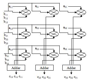
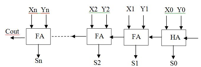
correspondingbitsoftwobinarynumbersandcarrybitofthe previous adder. It produces sum bits and carry bit for the nextstageadder.Inthisaddermultiplecarryproducedby multipleaddersarerippled,i.e.carrybitproducedfroman adder works as one of the input for the adder in its succeedingstage.HencesometimesitisalsoknownasRipple CarryAdder(RCA).Generalizeddiagramofparalleladderis showninfigure3.
adder are the two basic types of adders. Almost all other adders are made with the different arrangements of these twobasicaddersonly.Halfadderisusedtoaddtwobitsand producesumandcarrybitswhereasfulladdercanaddthree bitssimultaneouslyandproducessumandcarrybits.
Fig -1:ParallelAdder(n=7forSPFPandn=10forDPFP)
Ann-bitparalleladderhasonehalfadderandn-1fulladders ifthelastcarrybitrequired.Butin754multiplier’sexponent adder,lastcarryoutdoesnotrequiredsowecanuseXOR Gateinsteadofusingthelastfulladder.Itnotonlyreduces theareaoccupiedbythecircuitbutalsoreducesthedelay involved in calculation. For SPFP and DPFP multiplier’s exponentadder,hereweSimulate8bitand11bitparallel addersrespectivelyasshowinfigure4.
Fig -3:CarrySelectAdder
ProposedParallel-ParallelInputandMultiOutput(PPI-MO)
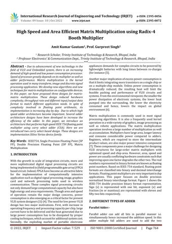
In this design, we opted for faster operating speed by increasing the number of multipliers and registers performing the matrix multiplication operation. From equation2wehavederivedforparallelcomputationof3×3 matrix-matrixmultiplicationandthestructureisshownin figure4.
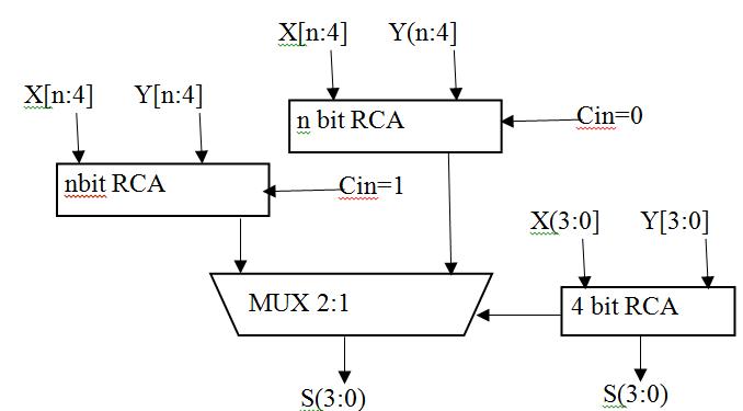
Fig -2:ModifiedParallelAdder(n=7forSPFPandn=10for DPFP)
Carry Select Adder:-
CarryselectadderusesmultiplexeralongwithRCAsinwhich thecarryisusedasaselectinputtochoosethecorrectoutput sum bits as well as carry bit. Due to this, it is called Carry selectadder.Inthisadder twoRCAsareusedtocalculatethe sum bits simultaneously for the same bits assuming two different carryinputsi.e.‘1’ and‘0’.Itistheresponsibilityof multiplexertochoosecorrectoutputbitsoutofthetwo,once the correct carry input is known to it. Multiplexer delayis included in this adder. Generalized figure of Carry select adderisshowninfigure3.9.Addersarethebasic building blocksofmostoftheALUs(Arithmeticlogicunits)usedin Digital signal processing and various other applications. Manytypesofaddersareavailableintoday’sscenarioand manymorearedevelopingdaybyday.HalfadderandFull
Forann×nmatrix–matrixmultiplication,theoperationis performedusing 2 n numberof multipliers, 2 n numberof registersand n n 2 numberofadders.Theregistersare used to store the partial product results. Each of the 2 n numberofmultipliershasoneinputfrommatrixBandthe otherinputisobtainedfromaparticularelementofmatrixA.
2022, IRJET | Impact Factor value: 7.529 | ISO 9001:2008 Certified Journal | Page765
International Research Journal of Engineering and Technology (IRJET) e-ISSN: 2395-0056
Volume: 09 Issue: 10 | Oct 2022 www.irjet.net p-ISSN: 2395-0072
ThedataflowformatrixBisinrowmajororderandisfed simultaneouslytotheparticularrowofmultiplierssuchthat the th i rowofmatrixBissimultaneouslyinputtothe th i rowofmultipliers,where1<i<n.Theelementsofmatrix are input to the multipliers such that, th i j ) , ( element of matrixAisinputtothe th j i ) , ( multiplier,where1<i,j<n. Theresultantproductsfromeachcolumnofmultipliersare thenaddedtogivetheelementsofoutputmatrixC.Inone cycle, n elements of matrix C are calculated, so the entire matrix the elements of matrix C are obtained in column major order with n elements multiplication operation requiresncyclestocomplete.
Let us consider the example of a 3×3 matrix – matrix multiplicationoperation,forabetteranalysisofthedesign (asshowninfigure1).Thehardwarecomplexitiesinvolved for this design are 9 multipliers, 9 registers and 6 adders. Elements from the first row of matrix B (b11 b12 b13) are inputsimultaneouslytothefirstrowofmultipliers(M11 M12 M13)in3cycles.Similarly,elementsfromothertworowsof matrix B are input to the rest two rows of multipliers. A single element from matrix A is input to each of the multiplierssuchthat, th i j ) , ( elementofmatrixAisinputto the multiplier Mij, where 1 < i,j < 3. The resultant partial products from each column of multipliers (M1k M2k M3k where 1 < k 3) are added up in the adder to output the elementsofmatrixC.Ineachcycle,onecolumnofelements frommatrixCisobtained(C1kC2kC3kwhere1<k<3)andso theentirematrixmultiplicationoperationiscompletedin3 cycles.
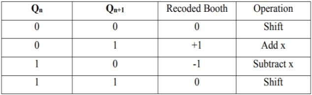
There is no need to take the sign of the number into deliberation in dealing with unsigned multiplication. However in signed multiplication the process will be changedbecausethesignednumberisina2’scompliment pattern which would give a wrong result if multiplied by usingsimilarprocessforunsignedmultiplication[6].Booth’s algorithmisusedforthis.Booth’salgorithmpreservesthe sign of the result. Booth multiplication allows for smaller, faster multiplication circuits through encoding the signed numbers to 2’s complement, which is also a standard techniqueusedinchipdesign,[6]andprovidessignificant improvementsbyreducingthenumberofpartialproductto half over “long multiplication” techniques. Radix 2 is the conventionalboothmultiplier.
Inboothmultiplication,partialproductgenerationisdone based on recoding scheme e.g. radix 2 encoding. Bits of multiplicand (Y) are grouped from left to right and correspondingoperationonmultiplier(X)isdoneinorderto generate the partial product [19]. In radix-2 booth
multiplicationpartialproductgenerationisdonebasedon encoding which is as given by Table1. Parallel Recoding scheme used in radix-2 booth multiplier is shown in the Table1.
To further decrease the number of partial products, algorithms with higher radix value are used. In radix-4 algorithmgroupingofmultiplierbitsisdoneinsuchaway thateachgroupconsists of 3bitsasmentionedintable 1. Similarlythenextpairistheoverlappingofthefirstpairin whichMSBofthefirstpairwillbetheLSBofthesecondpair andothertwobits.Numberofgroupsformedisdependent onnumberofmultiplierbits.Byapplyingthisalgorithm,the number of partial product rows to be accumulated is reduced from n in radix-2 algorithm to n/2 in radix-4 algorithm. The grouping of multiplier bits for 8-bit of multiplicationisshowninfigure5.
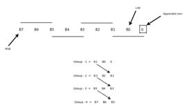
For8-bitmultiplierthenumbergroupsformedisfourusing radix-4 booth algorithm. Compared to radix-2 booth algorithmthenumberofpartialproductsobtainedinradix-4 boothalgorithmishalfbecausefor8-bitmultiplierradix-2 algorithmproduceseightpartialproducts.Thetruthtable andtherespectiveoperationisdepictedintable1.Similarly whenradix-8boothalgorithmisappliedtomultiplierof8bitseachgroupwillconsistsoffourbitsandthenumberof groups formed is 3. For 8x8 multiplications, radix-4 uses fourstagestocomputethefinalproductandradix-8booth algorithmusesthreestagestocomputetheproduct.Inthis thesis, radix-4 booth algorithm is used for 8x8 multiplicationsbecausenumbercomponentsusedinradix-4 encodingstyle.
Factor value: 7.529 | ISO 9001:2008 Certified Journal
International Research Journal of Engineering and Technology (IRJET) e-ISSN: 2395-0056
Volume: 09 Issue: 10 | Oct 2022 www.irjet.net p-ISSN: 2395-0072
PPI-MO
MM using PFI-MO 34 55 38 9.128
Allthedesigningandexperimentregardingalgorithmthat we have mentioned in this paper is being developed on Xilinx 6.2i updated version. Xilinx 6.2i has couple of the striking features such as low memory requirement, fast debugging, and low cost. The latest release of ISETM (IntegratedSoftwareEnvironment)designtoolprovidesthe lowmemoryrequirementapproximate27percentagelow. ISE 6.2i that provides advanced tools like smart compile technologywithbetterusageoftheircomputinghardware providesfastertimingclosureandhigherqualityofresults forabettertimetodesigningsolution.
Table -3: ComparisonResult
Table -4: Simulationresultfor3×3and4×4Matrix Multiplication
Structure Dimension Slice LUTs IOBs Delay(ns)
Previous Design[1]
3×3
112 164 81 15.517 MM using PPI-SO 44 15 34 11.222 MM using 93 154 74 15.058
Previous Design[1]
4×4
248 412 96 17.227 MM using PPI-SO 49 88 42 13.771 MM using PPI-MO 221 388 74 15.058 MM using PFI-MO 39 72 48 11.543
Most of the digital signal processing (DSP) algorithms is formulated as matrix-matrix multiplication, matrix-vector multiplicationandvector-vector(Inner-productandouterproduct) form. Few such algorithms are digital filtering, sinusoidal transforms, wavelet transform etc. The size of matrix multiplication or inner-product computation is usuallylargeforvariouspracticalapplications.Ontheother hand,mostofthesealgorithmsarecurrentlyimplementedin hardware to meet the temporal requirement of real-time application [9]. When large size matrix multiplication or innerproductcomputationisimplementedinhardware,the design is resource intensive. It consumes large amount of chipareaandpower.Withsuchavastapplicationdomain, newdesignsarerequiredtocatertotheconstraintsofchip areaandpowerandhighspeed.
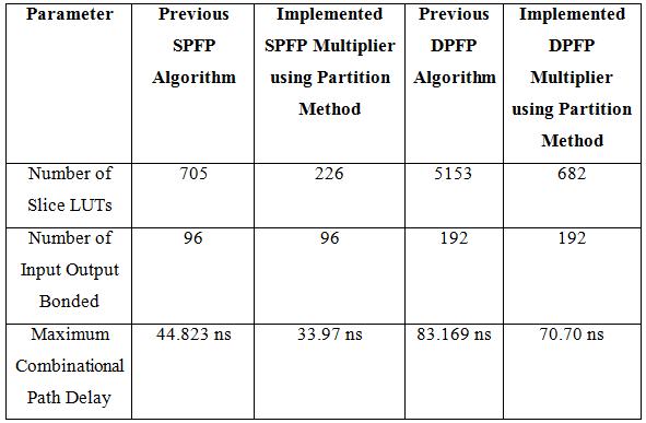
IEEE754 standardize two basic formats for representing floating point numbers namely, single precision floating point and double precision floating point. Floating point arithmetichasvastapplicationsinmanyareaslikerobotics andDSP.Delayprovidedandarearequiredbyhardwareare thetwokeyfactorswhichareneedtobeconsiderHerewe present single precision floating point multiplier by using twodifferentaddersnamelymodified CSAwithdualRCA andmodifiedCSAwithRCAandBEC.
[1] DiYan,Wei-XingWang,LeiZuo, Member,IEEE andXiaoWei Zhang, “Revisiting the Adjoint Matrix for FPGA Calculating the Triangular Matrix Inversion”, IEEE TransactionsonCircuitsandSystemsII:ExpressBriefs, 2020.
[2] X.-W.Zhang,L.Zuo,M.LiandJ.-X.Guo,“High-throughput FPGA implementation of Matrix inversion for control systems,”Acceptedby IEEE Trans. Ind. Electron.,2020.
[3] C. Zhang, et al,. “On the low-complexity, hardwarefriendly tridiagonal matrix inversion for correlated massiveMIMOsystems,” IEEETrans.Vehic.Tech.,vol.68, no.7,pp.6272-6285,Jul.2019.
International Research Journal of Engineering and Technology (IRJET) e-ISSN: 2395-0056 Volume: 09 Issue: 10 | Oct 2022 www.irjet.net p-ISSN: 2395-0072
[4] Y.-W. Xu, Y. Xi, J. Lan and T.-F. Jiang, “An improved predictivecontrollerontheFPGAbyhardwarematrix inversion,” IEEE Trans. Ind. Electron.,vol.65,no.9,pp. 7395–7405,Sep.2018.
[5] LakshmikiranMukkaraandK.VenkataRamanaiah,“A Simple Novel Floating Point Matrix Multiplier VLSI Architecture for Digital Image Compression Applications”, 2nd International Conference on Inventive Communication and Computational Technologies(ICICCT2018).
[6] Soumya Havaldar, K S Gurumurthy, “Design of Vedic IEEE754FloatingPointMultiplier”,IEEEInternational ConferenceOnRecentTrendsInElectronicsInformation CommunicationTechnology,May20-21,2016,India.
[7] Ragini Parte and Jitendra Jain, “Analysis of Effects of using Exponent Adders in IEEE- 754 Multiplier by VHDL”,2015InternationalConferenceonCircuit,Power and Computing Technologies [ICCPCT] 978-1-47997074-2/15/$31.00©2015IEEE.
[8] Ross Thompson and James E. Stine, “An IEEE 754 Double-Precision Floating-Point Multiplier for DenormalizedandNormalizedFloating-PointNumbers”, InternationalconferenceonIEEE2015.
[9] M. K. Jaiswal and R. C. C. Cheung, “High Performance FPGAImplementationofDoublePrecisionFloatingPoint Adder/Subtractor”,in InternationalJournalofHybrid InformationTechnology,vol.4, no.4, (2011)October
[10] B. Fagin and C. Renard, "Field Programmable Gate Arrays and Floating Point Arithmetic," IEEE TransactionsonVLS1,vol.2,no.3,pp.365-367,1994.
[11] N. Shirazi, A. Walters, and P. Athanas, "Quantitative Analysis of Floating Point Arithmetic on FPGA Based CustomComputingMachines,"ProceedingsoftheIEEE SymposiumonFPGAsforCustomComputingMachines (FCCM"95),pp.155-162,1995.
[12] MalikandS.-B.Ko,“AStudyontheFloating-PointAdder in FPGAs”, in Canadian Conference on Electrical and ComputerEngineering(CCECE-06),(2006)May,pp.86–89.
[13] D. Sangwan and M. K. Yadav, “Design and ImplementationofAdder/SubtractorandMultiplication Units for Floating-Point Arithmetic”, in International JournalofElectronicsEngineering,(2010),pp.197-203.
[14] L.Louca,T.A.CookandW.H.Johnson,“Implementation of IEEE Single Precision Floating Point Addition and Multiplication on FPGAs”, Proceedings of 83rd IEEE SymposiumonFPGAsforCustomComputingMachines (FCCM‟96),(1996),pp.107–116.
[15] Jaenicke and W. Luk, "Parameterized Floating-Point Arithmetic on FPGAs", Proc. of IEEE ICASSP, vol. 2, (2001),pp.897-900.
[16] Lee and N. Burgess, “Parameterisable Floating-point OperationsonFPGA”,ConferenceRecordoftheThirtySixth Asilomar Conference on Signals, Systems, and Computers,(2002).
[17] M. Al-Ashrafy, A. Salem, W. Anis, “An Efficient Implementation of Floating Point Multiplier”, Saudi International Electronics, Communications and PhotonicsConference(SIECPC),(2011)April24-26,pp. 1-5.
2022, IRJET | Impact Factor value: 7.529 | ISO 9001:2008 Certified Journal |