International Research Journal of Engineering and Technology (IRJET) e-ISSN: 2395-0056

Volume: 09 Issue: 10 | Oct 2022 www.irjet.net p-ISSN: 2395-0072
International Research Journal of Engineering and Technology (IRJET) e-ISSN: 2395-0056
Volume: 09 Issue: 10 | Oct 2022 www.irjet.net p-ISSN: 2395-0072
2
1 Research Scholar, Trinity Institute of Technology & Research, Bhopal, India
2 Professor Electronics’ & Communication Dept., Trinity Institute of Technology & Research, Bhopal, India ***
Abstract - The DWT is expressed in a generalized form know as discrete wavelet transform which analyzes both the low and high sub bands at every levelof breakdownwithequal priority. A pragmatic approach to signal processing is provided by the DWT mathematical technique. It is frequently utilized in many signal and image processing applications because of its many beneficial qualities, suchasadaptivetimefrequency window, decreased aliasing distortion,andefficient computing complexity. In order to compress images and videos, 2-D DWT is frequently utilized. But in some DWT architectures, flipping approach adds considerable design complexity. In order to give multiplier-less implementation and ensure that our suggested work would function for every bit, we have included the BK adder and MDA approach. In comparison to the previous approach, the suggestedMDA and MCSLA-based 2-D DWT algorithm exhibits goodperformance. The suggested architecture for DWT implementation minimizes the maximum combinational path delay while also reducing chip size and computation time.
Key Words: VHDLSimulation,2-DDWT,MDA,Low-pass Sub-band(LPSB),High-passSub-band(HPSB)
Engineeringprofessionalschoosedigitalsignalprocessing methods based on the characteristics of the signal being studied.Thetwomainmethodsutilizedcommonlyforsignal analysis are frequency-based and time-frequency-based methods.Astationarysignalisanalyzedusingthefrequencybased method (FBT), while non-stationary signals are typicallyanalyzedusingtime-frequencytechniques(TFT), such as the short time Fourier transform (STFT), wavelet transform, etc.Although no informationisobtainedinthe time domain, the FBT offers energy information of the function in the frequency domain. A musical note or a vehicle'snoisesareexamplesofnon-stationarysignalsfrom which the TFT captures the transient properties and representstheminatime-frequencymapforsignalanalysis. [1,2].
Over the years wavelet transform has emerged as a predominant tool for time-frequency decomposition of a signal. Wavelet is designed especially to study the nonstationary data, and due to its generality and accurate results,ithasbecomeusefulinanumberofareas.Foranonstationarysignal,thefrequencycontentataparticularpoint
in time is different from the frequency content at another point,e.g.,asuddentransient[3].TheFouriertransformis not able to specify accurately at what point in time the transientoccursbecausetheFourierbasesaresinusoidsthat areinfiniteinextentandcangiveinformationonlybasedon theentiredurationofthesignal.Hence,theFourierbasesare notabletolocalizetheimportanteventsofthesignal.Onthe contrary, wavelet has bases of finite duration, and this property enables it to identify and locate in time the important events in the signal which can be used to differentiateonesignalfromtheotherefficiently[4,5].
Wavelet analysis allows researchers to isolate and manipulate the specifictype ofinformationhiddeninthe data,similartothehumanearpickingthesoundoftheflute inasymphony.Adiversevarietyofwaveletscanbeusedto analyzeasignal,thetypeofwavelettobeuseddependson theapplication.Waveletisfoundindifferentbranchesfrom thesignalanalysistotheproblemsinengineering,physics, and mathematics. In the signal processing application, wavelet is mainly used in analyzing the non-stationary signals to provide the time-frequency information of an important transient [6]. In the bio-medical engineering, earth or ocean engineering the transient always carry a significantamountofinformationfortherespectivedomain. Thewavelettransformisfoundtobeparticularlyusefulfor analyzingthesignalsthatareconsideredtobeaperiodicand noisy.Theabilitytoanalyzeasignaldistinctlybothintime and frequency simultaneously has set wavelet transform apart from the STFT. Hence, wavelet transform is used to investigateavarietyofphysicalphenomenasuchasclimate changeanalysis,heartmonitoring,seismicsignalde-noising, astronomical image de-noising, video and image compression[7,8].
The history of DWT goes back to the year 1976 when a techniquewasinventedbyCroiser,Galand,andEstebanto decompose the discrete time signals. In the same year, Flanagan,Crochiere,andWeberconductedasimilaranalysis onthevoicesignal.Thetechniquewasnamedassub-band coding.Burtdevelopedamethodknownaspyramidalcoding in1983thatiscomparabletosub-bandcoding,sometimes referred to as multi-resolution analysis. The pyramidal codingsystemstillhadredundantinformationthatmightbe removed. By removing the redundant code from the
International Research Journal of Engineering and Technology (IRJET) e-ISSN: 2395-0056
Volume: 09 Issue: 10 | Oct 2022 www.irjet.net p-ISSN: 2395-0072
pyramidalcodingin1989,VetterliandLeGallimprovedthe sub-band coding [9]. The DWT, when compared with the CWT is considerably easier to develop and implement. Although the CWT can be discretized and computed for DWT,theaccuratediscretetransformisnotobtained.The informationprovidedbythissampledversionoftheCWTis highly redundant. On the other hand, analyzing this redundantinformationtakesalotoftimeandenergy.The DWT, on the other hand, speeds up processing while still extractingenoughusabledata fromthesignal foranalysis and synthesis. The DWT decomposes the input spectrum intotwosub-bands,namelythehigh-passsubbandandthe low-pass sub-band. A low-pass filter is used to filter the inputsignaltoproducealow-passsub-band,whileahighpassfilterisusedtoproduceahigh-passsub-band[10].A finite impulse response (FIR) filter with a short length is usedtocreatethelow-passandhigh-passfilters.Thispairof low-passandhigh-passfilterformaquadraturemirrorfilter (QMF) for the perfect signal reconstruction. The computationoftheDWTusinglowpassandhigh-passfilters is performed either by the convolution scheme or lifting scheme[11].
oftwopiecesofinformation,inthiscase3downto0,means thattherangeoftheinformationisfrom0to15.
Fig -1:TwoLevelDiagramofDiscreteWaveletTransform
Particularfocusisplacedonsystemperformanceandcostin digitalsystems.Effectiveperformancetypicallycomeswitha largerpricecost.However,withamoderateincreaseinthe hardware,betterperformancecanbeobtained.Inthecourse of a computation, addition and multiplication are the fundamentaloperationsthatareperformedfrequently.The speed with which these operations are performed has a great impact on the overall performance of the digital system.Sincethebeginningofthedigitalcomputers,many fastalgorithmsforthebasicarithmeticoperationshavebeen developedandimplemented[12,13].
There has been continuous research and development towards the newer algorithms. The main reason for the emergingalgorithmsistherapidchangeinthetechnology usedtoimplementthesearithmeticoperations.Besidesthe dependence on the technology used to implement the algorithm, it is the unique feature of the algorithm that affectstheperformanceofthearithmeticoperator[14].
Inthisstreamgraph,thedoubleinformationisconnectedto theserialinserialoutregister.IntheDWTdesign,allwhole numbersarerelatedtothetwofoldframe.Thewordlength
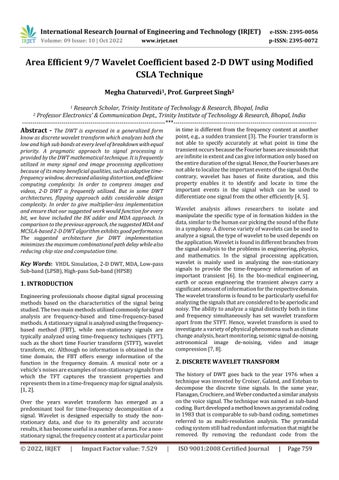
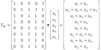
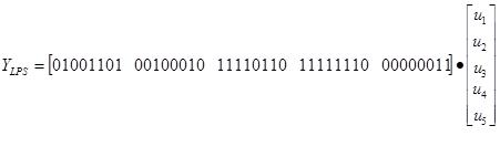
Fig -2:BlockDiagramof9/7WaveletCoefficientbased DiscreteWaveletTransform IftakestheLPScoefficientsh0,h1,h2,h3,andh4 multiplyby u1,u2,u3,u4andu5thenmultiplier-less1-DDWTLPSoutput is
h h h h YLPS
International Research Journal of Engineering and Technology (IRJET) e-ISSN: 2395-0056
Volume: 09 Issue: 10 | Oct 2022 www.irjet.net p-ISSN: 2395-0072
AlltheLPScoefficientarrangesdowntoupisbelow:
AllrowspassthroughlookuptableandreplaceLPS coefficienttoinput
If a XOR gate is realized with less number of gates in AOI logic, then there is a chance for reduction in the area and power consumption. Hence, we used alternative expression/approach for the XOR gate which is shown in equation1.
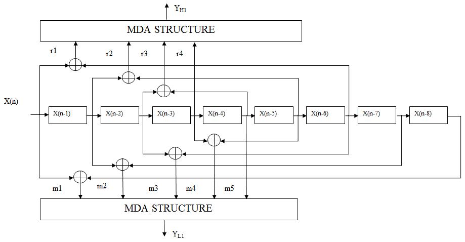
Table -1: ThesizeofRCAandCSLAgroupsareusedin4-, 8-,16-,32-and64-bitconventionalsqrtCSLAadder
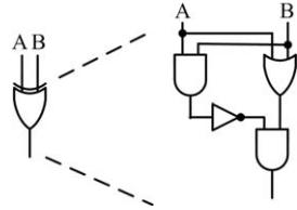
TheXORgateisshowninFig.3,wecallitasmodifiedXOR gate.TheadvantageofthemodifiedXORgateisneededonly four and nine gates for implementing HA and FA respectively.Furthermore,amodifiedXORcanactasHA.In theconventionalXORgate,NOTgatesarefollowedbyAND gatesand,finally,ORgateispresentedbutinthemodified XORgateANDandORgatesarepresentedinthefirststage. Consequently,anadditionalANDgateisnotrequiredtofind carry of HA. Further, only four gates are needed to implementthemodifiedXORgate.ThismodifiedXORgate was used inside RCA and CSLA to reduce the gate count whichleadstoreductioninareaaswellasreductioninthe power consumption of the CSLA. Moreover, the design is quiteeasybecausetheconventionalXORgateisreplacedby themodifiedXORgate.
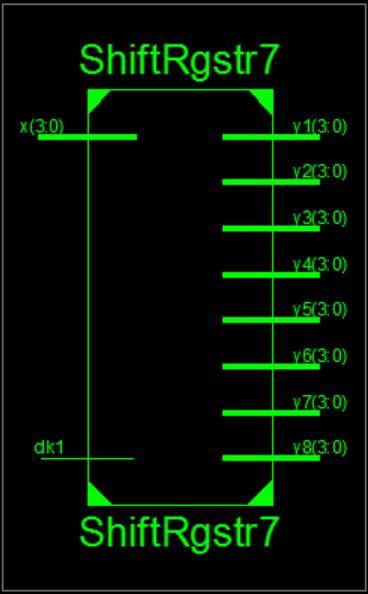
Thissectiondisplaystheresultsofthe2-DDWT'ssynthesis utilizing the MDA and MCSLA techniques. The view technology schematic (VTS), register transfer level (RTL) view,hardwareandsynthesisutilization,VHDLtestbench, and comparison of the 2-D DWT design for existing architectureareallexplainedinthissection.Shiftregisters, various bits of the BK adder, and the multiplier-less MDA approachmakeupthe2-DDWTarchitecture.
Fig -4:VTSfor4-bitSR
International Research Journal of Engineering and Technology (IRJET) e-ISSN: 2395-0056
Volume: 09 Issue: 10 | Oct 2022 www.irjet.net p-ISSN: 2395-0072
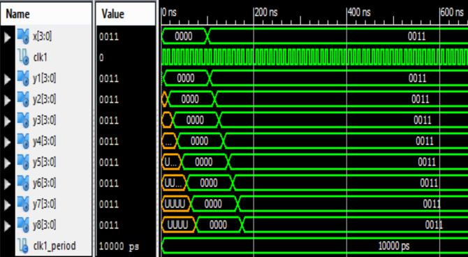
Fig -5:RTLfor4-bitSR
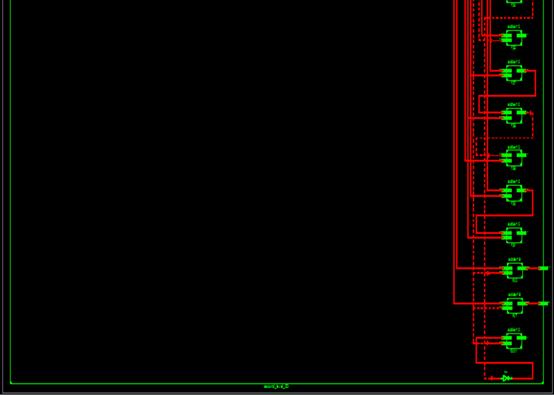
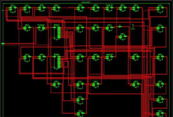
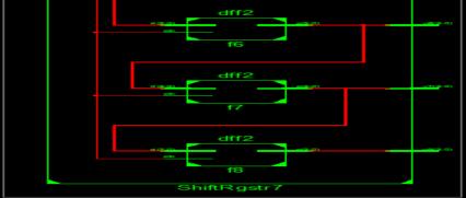
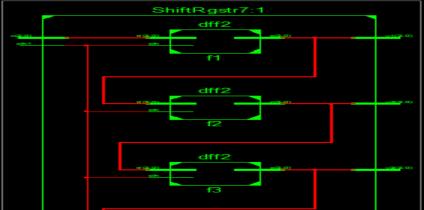
Fig -6:VHDLTest-benchinShiftRegister
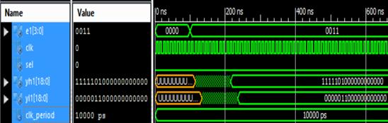
Figure 7 depicts the second level DWT in RTL. It includes everyelementofa2-DDWT.Itincludeseveryshiftregister, D-flipflop,andMCSLA.Theviewtechnologyisdependenton thisRTLschematic.
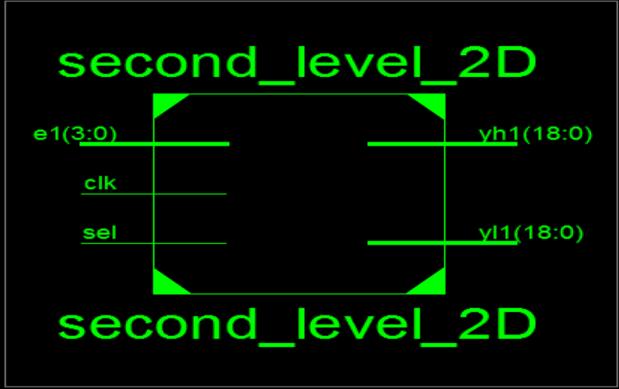
Fig -8:RTLfor2-DDWT
Thisfigure9showsthewaveformofthesecondlevelDWT. Heretheinputisgivenas‘0011’andtheoutputfinallycomes forboththefilters.‘yh’is‘1111101000000000000’forhigh passfilteroutputand‘yl’is‘0000011000000000000’forlow passfilteroutput.
Fig -7:VTSfor2-DDWT
International Research Journal of Engineering and Technology (IRJET) e-ISSN: 2395-0056
Volume: 09 Issue: 10 | Oct 2022 www.irjet.net p-ISSN: 2395-0072
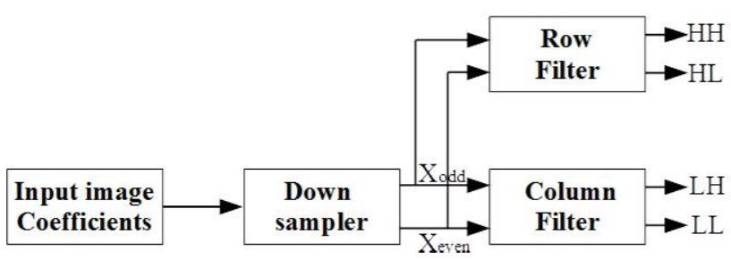
ForthisMDAtechniqueisusedwhichprovidesapproachfor multiplier less implementation. It contains adder, shift registersandfreeofmultiplier.
Finallywehavedesignedthe1-Dand2-DDWTusingMCSLA and MDA technique which provide better efficiency and showsbetterresultsthanthepreviousdesign.
DWT has been an important technique of multimedia applications. This is not only the key algorithm of signal processing,buthasalsoledtorevolutionsinimageandvideo coding algorithms. There are many DWT architectures of flippingtype,foldedtypeandpipelinearchitectureforsignal transform. Each structure has its own advantages and disadvantages.However,anefficientarchitecturedesignof DWT in JPEG 2000 is an important area of research to explore.
[1] Jhilam Jana, Sayan Tripathi, Ritesh Sur Chowdhury, Akash Bhattacharya and Jaydeb Bhaumik, “An Area Efficient VLSI Architecture for 1-D and 2-D Discrete WaveletTransform(DWT)andInverseDiscreteWavelet Transform(IDWT)”,DevicesforIntegratedCircuit,IEEE 2021.
[2] Zhang, W., Wu, C., Zhang, P. and Liu, Y., “An Internal Folded Hardware-Efficient Architecture for LiftingBased Multi-Level 2-D 9/7 DWT”, 2019, Applied Sciences,9(21),p.4635.
[3] SamitKumarDubey,Arvind KumarKouravandShilpi Sharma,“HighSpeed2-DDiscreteWaveletTransform using Distributed Arithmetic and Kogge Stone Adder Technique”, International Conference on CommunicationandSignalProcessing,April6-8,2017, India.
[4] RakeshBiswas,SiddarthReddyMalreddyandSwapna Banerjee, “A High Precision-Low Area Unified Architecture for Lossy and Lossless 3D Multi-Level Discrete Wavelet Transform”, IEEE Transactions on CircuitsandSystemsforVideoTechnology,Vol.45,No. 5,pp.01-11,May2017.
[5] Mamatha I, Shikha Tripathi and Sudarshan TSB, “PipelinedArchitectureforFilterBankbased1-DDWT”, International Conference on Signal Processing and IntegratedNetworks(SPIN),pp.47-52,May2016.
[6] MaurizioMartinandGuidoMasera,MassimoRuoRoch and Gianluca Piccinini, “Result-Biased DistributedArithmetic-BasedFilterArchitecturesforApproximately ComputingtheDWT”,IEEETransactionsonCircuitsand
Systems I: Regular Papers, Vol. 62, No. 8, pp. 21032113,August2015.
[7] Basant Kumar Mohanty, Pramod Kumar Meher, “Memory-Efficient High- Speed Convolution-based Generic Structure for Multilevel 2-D DWT”, IEEE transactionsonCircuits,SystemsforVideoTechnology, Vol.23,No.2,pp.353-363,February2013.
[8] BasantK.Mohanty,AnuragMahajan,PramodK.Meher, “Area- and Power-Efficient Architecture for HighThroughputImplementationofLifting2-DDWT”,IEEE TransactionsonCircuitsandSystems-II:ExpressBriefs, Vol.59,No.7,pp.434-438,July2012.
[9] ChengjunZhang, Chunyan Wang, M.OmairAhmad, “A PipelineVLSIArchitectureforHigh-SpeedComputation of the 1-D Discrete Wavelet Transform”, IEEE transactionsonCircuitsandSystems-I;RegularPapers, Vol.57,No.10,pp.2729-2740,October2010.
[10]Zhang,Chengjun,ChunyanWang,andM.OmairAhmad, “A pipeline VLSI architecture for high-speed computation of the 1-D discrete wavelet transform”, IEEE Transactions on Circuits and Systems I: Regular Papers,Vol.57,No.10,pp:pp.2729-2740,October2010.
[11]S.M.M.Rahman,M.O.Ahmad,andM.N.S.Swamy,“A NewStatisticalDetectorforDWT-BasedAdditiveImage WatermarkingusingtheGauss-HermitExpansion,”IEEE Transactions Image Processing, Vol. 18, No. 8, pp. 1782−1796,August2009.
[12]P.K.Meher,B.K.MohantyandJ.C. Patra,“HardwareEfficient Systolic-Like Modula Design for TwoDimensional Discrete Wavelet Transform”, IEEE Transactions on Circuits and Systems Ii: Express Briefs,Vol.55,No.2,pp.1021-1029,February2008.
[13]Chao Cheng, Keshab K. Parhi, “High-Speed VLSI Implementation of 2-D Discrete Wavelet Transform”, IEEETransactionsonSignalProcessing,Vol.56,No.1,pp. 393-403,January2008.
[14]C.C.Cheng,C.-T.Huang,C.-Y.Cheng,C.-Jr.LianandL.-G. Chen,“On-chipMemoryOptimizationschemeforVLSI Implementation of Line-Based 2-D Discrete Wavelet Transform,”IEEETransactionsoncircuitandSystemfor VideoTechnology,vol.17,no.7,pp.814-822,July2007.
[15]M.Martina,andG.Masera,“Multiplierless,folded9/75/3waveletVLSI Architecture,”IEEETransactionson Circuits and System, Express Brief Vol. 54, No. 9, pp. 770- 774,September2007.