International Research Journal of Engineering and Technology (IRJET) e-ISSN: 2395-0056

Volume: 09 Issue: 10 | Oct 2022 www.irjet.net p-ISSN: 2395-0072
International Research Journal of Engineering and Technology (IRJET) e-ISSN: 2395-0056
Volume: 09 Issue: 10 | Oct 2022 www.irjet.net p-ISSN: 2395-0072
NOONE AVINASH1 , SAMPATH PAMPANA2
1 M.Tech Student, Dept. of Mechanical Engg., Vidya Jyothi Institute of Technology, Hyderabad, India
2 Associate Professor, Dept. of Mechanical Engg., Vidya Jyothi Institute of Technology, Hyderabad, India ***
Abstract - AISI 316L steel is extensively used in marine application such as boat rails and hardware, facades of buildings, pharmaceutical and bio-processing, dairy and food, brewery and other beverage industries due to high corrosion and heat resistance along with outstanding fabricability and formability.
In the present work, the effect of Zirconia powder coating on the fatigue life and corrosion resistance of AISI 316L steel was examined. The characterization of base material and coating is done in terms of chemical composition, microstructure, surface roughness and hardness. Thereafter, low cycle fatigue tests and corrosion tests are conducted to examine the fatigue life and corrosion resistance.
It was found that the there was a reduction in fatigue life of the chosen material by around 5% due to the HVOF coating of Zirconia. However the corrosion resistance can be improved by around 30% due to the same. It is hence a trade-off conclusion between fatigue life and corrosion resistance, to be taken by engineers based on the application requirements.
Key Words: AISI 316L steel, Zirconia, HVOF coating, Fatigue life, Corrosion resistance
Machine is mechanical arrangement which utilises power for applying forces in order to manage movement as wellasotherpartswhichweutilizeinonaregularlivingwerefrequentlyundergonetomultipleforcesenclosed.Stresses as well as strains formed were occasionally periodic relative to direction of forces. Although degree of strain is less than theiryieldlimitsincetheyresultinfailurewhiletheywereusedanumberofschedulesatregularintervals.IfMaterialwas undergone to continuous series of stress or else strain, failure happens with foremost towards fracture at a few deficiencies,thiskindoffailurewasknowntobefatigue.
Fatigue deformation was formed with adaptive steps of rotating stress, tensile stress in addition to plastic strain. The plastic strain happening since cyclical stress initiate crack, tensile stress promote crack increase. Careful calculation of strainrepresenttominuteplasticstrainsmightbepresentonlowlevelbasedonstresssincethestrainmayorelseemerge into completely elastic. Even if compressive stresses mayn’t reason fatigue failure, Compressive loads will induce local tensilestresses.Thiswasrequiredforimplementingfewstepsfordevelopingfatiguelifeforcomponentsalsowithvarying geometry for components otherwise decreasing Resistance divergent close to material. Geometry adjust was never answer, particularly because of a few limitations. Thus fatigue life for element was raised with reducing strains of substance.Severalmethodslikeheattreatment,coatingetc.,willimprovefatiguelifeforsubstanceyetbeneathstudyallof ushavetomoveaheadwithinconsiderationstrains.
Stainless steels were low carbon alloy steels by chromium being main blend component. Corrosion resistance for steels wasbecauseofpresenceforaconsiderableamountforchromiumwhichcreatesformationforskinny,effectivedepositfor chromium-oxidethatdefendsexterioramongdecay.
AISI 316L Austenitic Stainless Steel was substance where corrosion resistance, fatigue life were analyzed over project. The Steel was mainly utilized for naval as well as marine practices since this contains outstanding corrosion resistance,largestrengthviaweightproportion.
International Research Journal of Engineering and Technology (IRJET) e-ISSN: 2395-0056
Volume: 09 Issue: 10 | Oct 2022 www.irjet.net p-ISSN: 2395-0072
Table -1: Equipmentusedduringtheresearchstudy
S.No Equipment 1 HighVelocityOxy-Fuelfacility 2 PlugNPlayforfatiguetesting
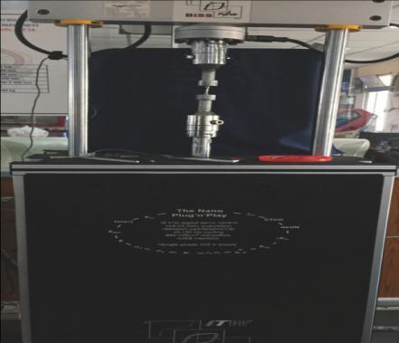
Thermal Spray coating is used globally in defending commercial parts among decay, abrasion, erosion, wear, surface fatigue, to guard substrates operating in high temperatures. Thermal spray coating procedures were divided as follows: plasma spray Process, flame thermal spray, high velocity oxy fuel (HVOF) spraying, cold spraying, arc spray process, and detonation gun method. In the current project, the selected component was laminated by ZrO2 using highvelocityoxy-fuelcoatingapparatus.ZrO2 wasmovedacrosscentralorificeofTorch, fuelgascombinedbyoxygenpassvia channelforTorch.LaterbecomingwarmednearendofTorch,moltenZrO2 wassprinkledoverjobinorderthisissprayed overspecimen.
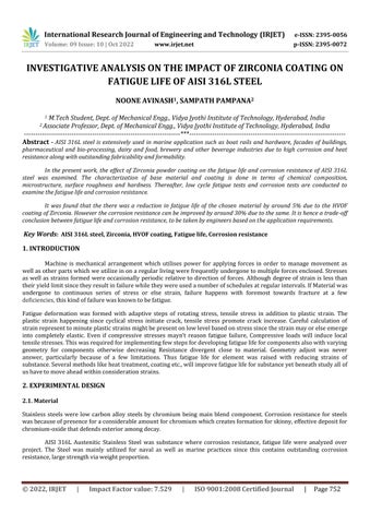
Plug-N-PlayFatigueTestingMachineinITWwasusedtodetectfatiguelifeforspecimens.Apparatus consistofcondition for using different Tensile, Compressive important reversed loads. This was given by computer data logger for notify amountofseriesenforcedthroughoutTest.
Fig -2:SpecimenmountedonthePlug-N-PlayFatigueTestingMachine
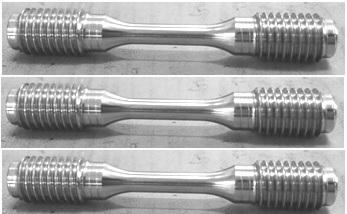
SolidroundsamplesareusedforLowfatiguetests.Testsaredonefor calculateLowcyclefatiguelifeanalysison uncoatedmaterial.
Material Type UncoatedAISI316LSpecimens
Roundsolidbars
International Research Journal of Engineering and Technology (IRJET) e-ISSN: 2395-0056
Volume: 09 Issue: 10 | Oct 2022 www.irjet.net p-ISSN: 2395-0072
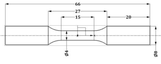
ChosenamountforsamplescontainingSolidroundbarfatiguesamplesoftypeAISI316LStainlesssteelareshop cuttorequired lengthand diameter. Thesize included66mmlengththroughthecompletespecimen diameter of10mm thickness. The complete specimens are prepared accordingly by ASTME 606 – 92 (Reapproved 1998) Standard. The properlymachinedinvestigationsamplesaresubjectedtoHVOFsprayingwithzirconiapowders.
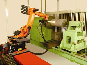
Material Type Number of coated specimens 300micronsZirconiacoatedAISI316LSpecimens Roundsolidbars 3
Figure 4: 300micronsAISI316Lspecimensjustsprayedwiththecoatingpowder.
InitiallythespecimensareplacedontoPlugNplayFatiguetestingapparatus.TheSpecimensaregrippedintothe jawsandlockedtightly.
Table 2: PlugNPlayFatiguetestingparameters
Loadcapacity 3KN
Cyclicwaveforms Sine,Triangle,Square,HSine,HTriangleandHSquare
Rampwaveform Single,DualandTrapezoidal
Frequencyrange 0.4Hz
Gapamongcolumns 400mm
Testingtype LowCycleFatigue Driveunit HydraulicSystem Amplitude 250Mpa Mean 0
International Research Journal of Engineering and Technology (IRJET) e-ISSN: 2395-0056
Volume: 09 Issue: 10 | Oct 2022 www.irjet.net p-ISSN: 2395-0072
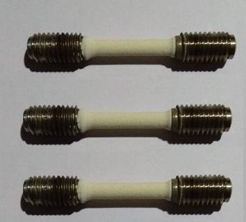
SamplesweremadeaccordingtoASTME606gradesbymeansofCNClathe.
Figure 5: Specimengeometryusedforfatiguetests.
FiniteElementMethodwasdoneforcalculateFatigueorTolerancebarrierforselectedcomponents,forestimating‘Stress (vs.) Fatigue Life’ arc. ANSYS 18.1 was utilized like instrument in order for carry out Finite Element Analysis. Strain life approach obtainable over ANSYS 18.1 Fatigue instrument was used to analysis. Strain-Life method extracts for consideration,localplasticstrainsbroughtatlocalizedpoints.
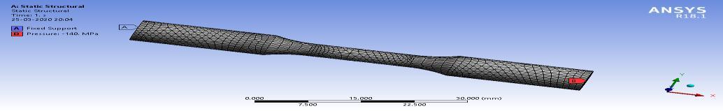
Tolerancelimits,Stress(vs.)FatigueLifecurvearecalculatedbyANSYS18.1.Forreplicatecircumstancesfortrial conducted, axial load with form for outward pressure is kept over right face, permanent assist is given to left face for sample.
Figure 6: BoundaryConditionsusedfortheanalysis
ParametersutilizedforfiniteelementfatigueanalysisforAISI316LinANSYS:
ModulusofElasticity(E)=193GPa
Poisson’sRatio(µ)=0.27
TensileStrength(UTS)=719MPa
FatigueStrengthCoefficient =1078.5MPa (taken as 1.5*UTS for steels)
FatigueStrengthExponent(b)=-0.087 (standard value of steels)
FatigueDuctilityCoefficient =0.59 (standard value of steels)
FatigueDuctilityExponent(c)=-0.58 (standard value of steels)
CyclicStrainHardeningExponent(n')=0.15 (taken as b/c)
CyclicStrengthCoefficient(K')=1167.21MPa (taken as ( ) ⁄ )
2022, IRJET | Impact Factor value: 7.529 | ISO 9001:2008 Certified
International Research Journal of Engineering and Technology (IRJET) e-ISSN: 2395-0056
Volume: 09 Issue: 10 | Oct 2022 www.irjet.net p-ISSN: 2395-0072
Figure 7(a): Normal stressinx-direction
Finite element fatigue runs were taken among 40 variable loadings, the stress (vs) fatigue life curve was drawn through corresponding stress, fatigue life results. Table 4.1 encloses stress, fatigue life values also curve was drawn in Figure 4.4. Magnified direction for Low cycle fatigue area for stress (vs.) fatigue life curve was revealed in Figure 4.5. Toleranceboundarywasseenas321.45MPaofAISI316Lbecausethiswasstressvaluegotoverfatiguelifefornearly106 cycles.EquivalentwillbeseenoverboldlineofRun2inbelowTable.
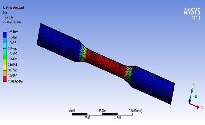
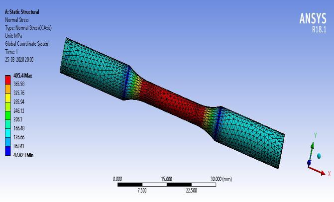
Table 3: FiniteElementFatigueresultsforAISI316L
Run Pressure (MPa) Normal Stress of X-direction (MPa) Fatigue Life (cycles)
1 110.5 319.98 1045300 2 111.01 321.45 1000700 3 115 333.01 720080 4 120 347.48 490440 5 125 362.94 343930 6 130 377.46 247690 7 135 391.84 182760 8 140 406.46 137830 9 145 420.84 106040 10 150 435.48 83030 11 155 449.82 66080 12 160 464.32 53360 13 165 478.70 43667 14 170 493.28 36155 15 175 507.76 30256 16 180 522.24 25567 17 185 536.72 21798 18 190 551.19 18734 19 195 565.67 16210 20 200 570.13 14138 21 205 584.81 12390 22 210 609.13 10938 23 215 623.59 9699
International Research Journal of Engineering and Technology (IRJET) e-ISSN: 2395-0056
24 220 638.06 8642 25 225 652.54 7735 26 230 667.02 6952 27 235 681.46 6273 28 240 695.98 5670 29 245 700.46 5169 30 250 724.94 4705 31 255 748.48 4301 32 260 753.84 3943 33 265 768.13 3624 34 270 782.85 3330 35 275 797.33 3085 36 280 811.84 2855 37 285 826.29 2649 38 290 830.76 2462 39 295 855.24 2292 40 300 869.72 2138
From the above research, it can be concluded that the Endurance limit value obtained from finite element method is accordance by real value for components. For AISI 316L, tolerance limit through finite element process (ANSYS 18.1) result was 321.45 MPa. Hence we can conclude that Finite Element Method can approximate the endurance limit with goodaccuracy.It canalso beconcluded thattheCoatingof ZrO2 overAISI 316L steel decreased fatigue life by 5%.HVOF coating method done, created oxide films evolution over foundation substance AISI 316L, as a result decreased their fatiguelife.Therefore,thiswastrade-offconclusionamongfatiguelifeaswellascorrosionresistancethroughengineering designstandpoint.
[1] D. Y. Shin, K. N. Kim, I.-T. Nam, and S. M. Han, “Improvementofcorrosionresistance ofstainlesssteelbyZrO2-SiO2 sol-gelcoatings,”MaterialsScienceForum,vol.510-511,pp.442–445,2006.
[2] N. Mamidi, J. J. Kumar, R. Nethi, and V. Kadali, “IMPACT OF NOTCH DEPTH ON THE FATIGUE LIFE OF AISI 316L AUSTENITICSTAINLESSSTEEL,”pp.1149–1151,2018.
[3] W. F. D. Radraj, C.M. Sonsino,Fatigueassessmentofweldedjointsbylocalapproaches,2001.
[4] Y. T. Li, B. Chen and C. F. Yan, “Effect of Parameters of Notch on Fatigue Life of Shaft Based on Product Lifecycle Management,”Mater.Sci.Forum,vol.638–642,pp.3864–3869,2010.
[5] G. Taguchi, SystemofExperimentalDesign,JohnWiley&Sons,NewYork,NY,USA,1987.
[6] R. Ebara, “Corrosion fatigue behaviour of ship hull structural steels,” in Proceedings of the International Coach Federation(ICF10),vol.32,Honolulu,Hawaii,USA,October2001.
[7] K. Hinkelmann and O. Kempthorne, Design and Analysis of Experiments, John Wiley & Sons, New York, NY, USA, 1966.
Volume: 09 Issue: 10 | Oct 2022 www.irjet.net p-ISSN: 2395-0072 © 2022, IRJET | Impact Factor value: 7.529 | ISO 9001:2008 Certified Journal | Page757
International Research Journal of Engineering and Technology (IRJET) e-ISSN: 2395-0056
Volume: 09 Issue: 10 | Oct 2022 www.irjet.net p-ISSN: 2395-0072
[8] P. Lassen, T. Récho, N. Darcis, “Statistical Models for Fatigue Life General Considerations for the S-N Approach,”Weld.J.,no.December,pp.183–187,2005.
[9] W. F. D. Radraj, C.M. Sonsino,Fatigueassessmentofweldedjointsbylocalapproaches,2001.
[10] T. Okawa, “FatigueLifePredictionof WeldedStructuresBased on Crack GrowthAnalysis,”NipponSteel Tech.Rep., no.102,pp.51–56,2013.
2022, IRJET | Impact Factor value: 7.529 | ISO 9001:2008 Certified Journal |