International Research Journal of Engineering and Technology (IRJET) e-ISSN: 2395-0056

Volume: 09 Issue: 10 | Oct 2022 www.irjet.net p-ISSN: 2395-0072
International Research Journal of Engineering and Technology (IRJET) e-ISSN: 2395-0056
Volume: 09 Issue: 10 | Oct 2022 www.irjet.net p-ISSN: 2395-0072
1Post Graduate Student, Dept. of Civil Engineering, Datta Meghe College of Engineering Airoli, Navi Mumbai- 400708, India
2Professor, Dept. of Civil Engineering, Datta Meghe College of Engineering Airoli, Navi Mumbai- 400708, India
3Professor, Dept. of Civil Engineering, Datta Meghe College of Engineering Airoli, Navi Mumbai- 400708, India ***
Abstract - A PendulumtypeTunedMassDamper(PTMD)isapassivestructuralvibrationcontroldevicewhichconsistsofa movingsecondarymasswhichissuspendedfromthemainstructureandconnectedtoexternaldampers.PlacingPTMDattop ormiddleorbottomstoreylevelswillhavedifferenteffectsonvibrationresponseofthestructure.Inthecurrentinvestigation, effectsofpositioningPTMDondifferentstoreylevelsareexplored.Anactualmodelof3storiedframedstructureshasbeen fabricatedanditsresponseundersinusoidalbaseexcitationiscomparedwithPTMDsuspendedfromdifferentstoreylevels. DifferentPTMDfrequency,massandpositionswereconsideredandmodelistestedforbaseexcitationsusingshaketable analysis.ThePTMDwithoutdampingisusedandonlytheeffectofvariationinfrequencyratio,massratioandpositionis considered.TheresponseofthestructurewasexperimentallydeterminedandcomparedfordifferentPTMDlocations.The resultsshowsignificantreductioninaccelerationandmaximumdisplacementoftheactualmodelwhenthePTMDisplacedat thetopfloor.BestresultoccurswhenthePTMDisonthetopfloorandthefrequencyratiois1.WhenPTMDistunedforthe1st modal frequency, placing it on 2nd or 1st floor makes it very ineffective and in some case increases the acceleration and displacementresponseofthestructure.
Key Words: PendulumtypeTunedMassDamper,PTMDposition,Resonance,Seismicresistance,Shaketableanalysis
Natural hazards like earthquake and wind presents an important problem of structural vibrations in tall and huge structures. Depending on their intensity, exterior vibrations can cause problems ranging from minor discomfort for the occupantstoseverestructuralharmorevencollapse[1].Latestdesignmethodsusetheinelasticdeformationstodissipatethe energyandmitigatethevibrationproblem.Manyolderstructuresmightnothavebeendesignedforresistingearthquakeloads. Henceexternalenergydissipationdevicesareusedtoaugmenttheperformanceofnewerandolderstructures.Oneofsuch deviceisaTunedMassDamper(TMD).TMDisapassivevibrationalcontroldevicewhichconsistsofanadditionalmassplaced insidethemainstructurewhichisconnectedtothemainstructureviaspringsanddampersthisallowsittomovewithrespect tothemainstructure.Whenthestructureisexcitedbytheexternalforces,italsoimpartsmotiontotheTMD,whichproduces restoringforceswhichareoutofphasewiththeexternalvibratingforcesduetowhichthestructuralvibrationresponseis reduced[2].TheTMDisusedtoavoidresonanceinthemainstructure.Resonanceoccurswhenthefrequencyofexternalforce issameasthenaturalfrequencyofthestructure[3]. ThusifthefrequencyoftheTMDiskeptneartothenaturalfrequencyof theprimarystructure,asignificantreductioninresponseofthestructureforthatforcingfrequencycanbeachieved[4].
The idea of TMD was originated by Frahm [5] who used a spring absorber then Den Hartog [6] first provided the optimizationmethodforundampedsystem.SincethenmanydifferenttypesofTMDhavebeendesigned.Oneofwhichisa Pendulum type Tuned Mass Damper (PTMD). PTMD works very similar to a TMD the only difference is that in TMD the secondarymasshastranslatingmotionbutinPTMDthesecondarymassissuspendedfromthemainstructurehenceitswings likeapendulum. DampersarealsoprovidedtothePTMDtodissipatethekineticenergyanditalsohelpsinreducingthe distancebywhichthePTMDmoves.Conventionally,thePTMDisprovidedatthetopstoreysofthestructurelikethePTMD fromthe92ndfloorintheTaipei101building[7].ThemainreasonofthisisthattheTMDshouldbeplacedatthelocation wherethemaximumamplitudeoftheparticularmodeshapeoccurs[2].ButifduetosomecircumstancesthePTMDisprovided onthemiddleorbottomstorylevels,andifitisnottunedproperly,thePTMDwillworkinadequatelyorevenworsenthe vibrationresponseofthestructure[8].
ThetuningofTMDisdonebyfindingoptimalparameterswhichareMassratio(μ),Frequencyratio(fr)andDampingratio (ζ),theseparametersaredefinedasfollows,
International Research Journal of Engineering and Technology (IRJET) e-ISSN: 2395-0056
Volume: 09 Issue: 10 | Oct 2022 www.irjet.net p-ISSN: 2395-0072
μ= (1) fr = (2) ζ= (3)
AMultiDegreeofFreedom(MDOF)structurehasmultiplenaturalfrequenciesfordifferentmodeshapes[3].TheTMDis tunedtoaparticularmodalfrequencyandthismodalfrequencyisthedominantmodeofthestructurewhoseamplitudeis highestcomparedtoothermodes.ATMDwithoutdampercanbetunedtoreducetheresponseofthestructureforasingle naturalfrequencyofthedominantmode.ButwhenTMDisaddedtothestructure,itaddsanextradegreeoffreedominthe structureandduetothisthereisanadditionalmodalfrequencyatwhichresonanceofthestructurecanoccurs[9,10]henceto reducetheresponseofTMDandstructureatthisnewfrequency,theoptimaldampingisnecessaryotherwiseatthisfrequency theTMDwillbelesseffectivetoreducetheresponse.
AlthoughadamperisanimportantelementinTMD,inthecurrentwork,aPTMDisusedwithoutthedamper.Themain objectiveistoobservehowthestructuralresponsechangeswhenthePTMDwhichistunedtoreducethestructuralresponse atthe1stdominantmodeisprovidedondifferentstoreylevels.Forthisanactualmodelof3storiedframestructurewithPTMD istestedforthebaseexcitationshavingfrequencysameasdominantmodeofthestructureanddifferentmassratiosand frequencyratiosofthePTMDarealsoconsidered.
TillnowmultiplestudiesarecarriedouttodetermineoptimalparametersforPTMDandderiveequationforthesame. AbubakarandFarid(2009)[11]obtainedageneralizedequationfortunedmassdamperwasmadeconsideringthedampingin themainstructure,whichwasnotincludedinDenHartog’swork.YanhuiLiu,etal.(2020)[12]carriedoutnumericaland experimentalanalysistofindoptimalparametersforTMDforMDOFstructure.GinoB.Colherinhas,etal.(2019)[13],foundout optimalparametersforaMDOFstructurebyconsideringequivalentSDOFsystem.RafikR.GergesandBarryJ.Vickery(2005) [14],providedequationsforoptimalparametersfordifferentsystemswithandwithoutdampinghavingdifferentforcing conditions.TheyalsofoundoutPTMDtobemoreeffectiveforwindexcitationthanearthquakeexcitations.PedroL.Bernardes Júnior,MarcusV.G.deMorais,SuzanaM.Avila(2019)[15],ExperimentallyanalysedaninvertedPTMDandexperimentally foundoutoptimalparametersforMDOFstructureandwasabletoreducestructuralresponseforarangeoffrequencies
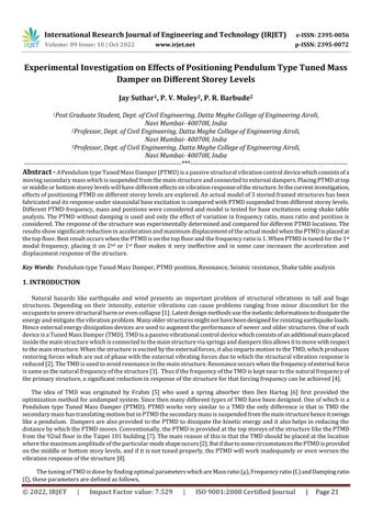
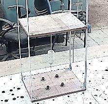
In the current study, a 3 storied frame structure without infill wall was considered which was provided with PTMD suspendedfrom1st,2ndand3rdfloor(oneflooratatime).Anactualmodelofthestructurewasfabricatedwhichconsistsof3 rigidfloorslabssupportedby4columns.Thecolumnsarerigidlyfixedtothebase.Fig.1(a)andFig.1(b)arediagramshowing themodelelevationandplanrespectively.Table1showsthematerialproperties.ThemodelistestedwithPTMDsuspended fromdifferentfloorsforsinusoidal(harmonic)baseexcitationusingshaketabletesting.Thevibrationresponseofthestructure withandwithoutPTMDismeasuredandcompared.
Themodelissymmetricandthecenterofmasscoincideswiththecenterofstiffness.ThePTMDissuspendedfromthecenter ofmassoneachfloor.
Material=Plywood,
Dimensions:Length=360mm,Width=260mm,Thickness=12mm, Density=8.458KN/m3 , LongitudinalModulusofElasticity=10800MPa, LongitudinalPoisson'sratio=0.3, LongitudinalModulusofRigidity=4154MPa.
International Research Journal of Engineering and Technology (IRJET) e-ISSN: 2395-0056
Volume: 09 Issue: 10 | Oct 2022 www.irjet.net p-ISSN: 2395-0072
Column Properties
Material=Aluminium, Dimensions:Width=19mm,Thickness=2mm, Density=27.1KN/m3 , ModulusofElasticity=70000MPa, Poisson'sratio=0.32, ModulusofRigidity=26516MPa.
Fig -1: FrameStructure3dView
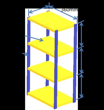
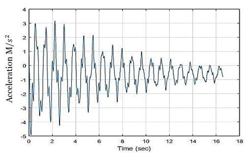
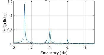
TheactualmodelshowninFig.4wasfabricatedwhichhadmassof3500gm.Tofindoutmodalfrequenciesofactualmodel, freevibrationtestwasconducted.Forfreevibrationtest,thebaseofthemodelwaskeptfixedandthetopfloorwasgivenan initialdisplacementalongthelongerspanofthemodel.Accelerationoftopfloorwasmeasuredduringthefreevibrationand FastFourierTransform(FFT)wascarriedoutontheaccelerationvstimedatatofindoutthenaturalfrequencies.Fig2andFig 3showsrecordedfreevibrationdataanditsFFTrespectively.
Fig -2: FreeVibrationAccelerationvsTimeGraph
2022, IRJET | Impact Factor value: 7.529 | ISO 9001:2008 Certified
International Research Journal of Engineering and Technology (IRJET) e-ISSN: 2395-0056
Volume: 09 Issue: 10 | Oct 2022 www.irjet.net p-ISSN: 2395-0072
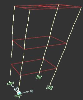
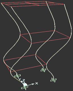
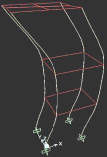
ThepeaksofFFTgraphshowsthenaturalfrequenciesofthestructurewhichwere1.2Hz,4Hzand6Hz,thesecorrespond tothe1st,2ndand3rdtranslationalmoderespectively.Thediagramsof1st,2ndand3rdtranslationalmodeshapesareshownin Figure5(a),Figure5(b)andFigure5(c)respectively. (a) (b) (c) Fig -5: ModeShapes
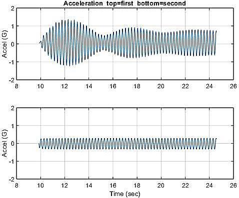
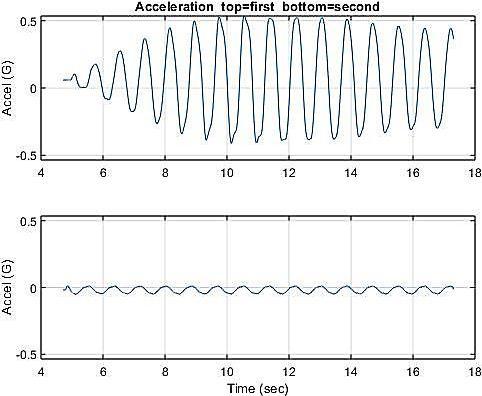
To test the structure under resonant condition, the actual model was tested for sinusoidal base excitations having frequencies1.2Hz(1stmodalfrequency)and4Hz(2ndmodalfrequency).Forthis,shaketabletestingwasused.Theamplitude ofshaketableexcitationwaskeptas5mm.Forthesetestsmaximumamplitudeofdisplacementoccurredattopfloor.Hence accelerationoftopfloorandalsotheshaketableweremeasured.Fromtopflooraccelerationandshaketableacceleration, relativedisplacementbetweentopfloorandbasewascalculated.Figure6showsthegraphsofrelativedisplacementfor1.2Hz baseexcitationandFigure7showsrelativedisplacementfor4Hzbaseexcitation.Theobservedmaximumoftopfloorrelative displacementfor1.2Hzbaseexcitationwas78.86mmandfor4Hzbaseexcitationitwas18.88mm.
International Research Journal of Engineering and Technology (IRJET) e-ISSN: 2395-0056
Volume: 09 Issue: 10 | Oct 2022 www.irjet.net p-ISSN: 2395-0072
Fig -6: Top(3rd)floorandbottomfloor(base) Fig -8: Top(3rd)floorandbottomfloor(base) accelerations(1.2Hzbaseexcitation) accelerations(4Hzbaseexcitation)

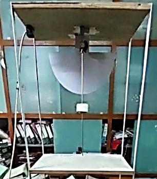
ThePTMDsetupconsistedofaweightsuspendedfrombottomofthefloorusingarelativelymasslessrod.ThePTMDwas suspendedfrom3rd,2nd,and1stflooroneflooratatimeasshowninFigure8(a),Figure8(b)andFigure8(c)respectively,and differentmassratio=0.05,0.1,0.15anddifferentfrequencyratio=0.8,1,1.3wereconsideredandtestedforsinusoidalbase excitationfortwodifferentfrequencies1.2Hzand4Hzkeepingtheamplitude5mm.Theaccelerationoftopfloorandshake tableweremeasuredforthetestswith1.2Hzbaseexcitation.Forthetestswherethebaseexcitationfrequencywas4Hzand PTMDwasattopfloor,themaximumdisplacementwasoccurringonthe2ndfloorhencetheaccelerationof2ndfloorand shaketableweremeasuredforthosetests.Relativedisplacementdatawascalculatedfromaccelerationreadings.
Although for high rise buildings, mass ratio is limited to 5% [17], larger mass ratios were considered for the test to determineeffectofchangeinmassratio.
Fig -8: PTMDAttachedon3rd,2ndand1stFloor Thegraphsofrelativedisplacementoftopfloorwithrespecttothebaseofseveraltestsareasfollows.
International Research Journal of Engineering and Technology (IRJET) e-ISSN: 2395-0056
Volume: 09 Issue: 10 | Oct 2022 www.irjet.net p-ISSN: 2395-0072
(Theapplicationofbaseexcitationsbeginsat10secondmarkandthevibrationsafterthe10secondmarkareconsideredfor thestructuralresponse).
Fig -9: Relativedisplacement(PTMDon3rd
Fig -10: Relativedisplacement(PTMDon2nd floor)(1.2Hzbasefrequency)(μ=0.05,fr=1) floor)(1.2Hzbasefrequency)(μ=0.05,fr=1)
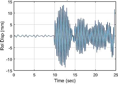
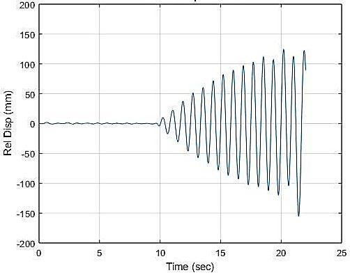
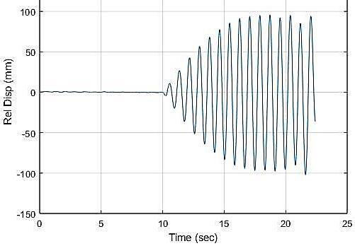
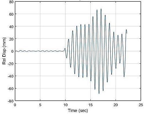
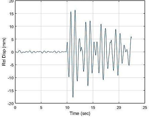
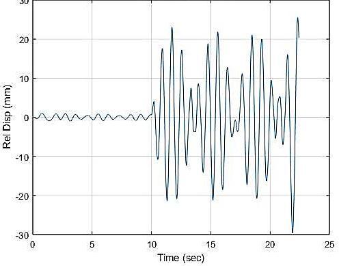
Fig -11: Relativedisplacement(PTMDon1st
Fig -12: Relativedisplacement(PTMDon1st floor)(1.2Hzbasefrequency)(μ=0.05,fr=1) floor)(1.2Hzbasefrequency)(μ=0.05,fr=1.3)
Fig -13: Relativedisplacement(PTMDon2nd
Fig -14: Relativedisplacementof floor)(1.2Hzbasefrequency)(μ=0.05,fr=1.3) 2ndfloorw.r.t.base(PTMDon3rdfloor) (4Hzbasefrequency)(μ=0.05,fr=1)
2022, IRJET | Impact Factor value: 7.529 | ISO 9001:2008 Certified Journal | Page26
International Research Journal of Engineering and Technology (IRJET) e-ISSN: 2395-0056
Fig -15: Relativedisplacement(PTMDon2nd
Fig-16: Relativedisplacement(PTMDon1st floor)(4Hzbasefrequency)(μ=0.05,fr=1) floor)(4Hzbasefrequency)(μ=0.05,fr=1)
Followingarethemaximumrelativedisplacements.(MaximumdisplacementwithoutPTMDfor1.2Hzexcitationwas 78.86mmandfor4Hzitwas18.88mm)
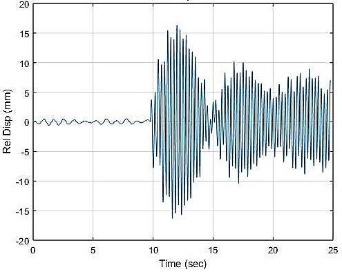
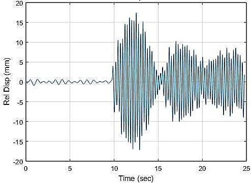
Table -2: MaximumDisplacementofTopFloor(mm)(PTMDPosition3rdFloor)(1.2Hzbaseexcitation)
μ fr
0.05 0.1 0.15 0.8 42.94 27.81 20.1 1 16.97 13.08 11.93 1.3 67.15 31.93 24.41
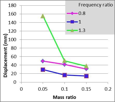
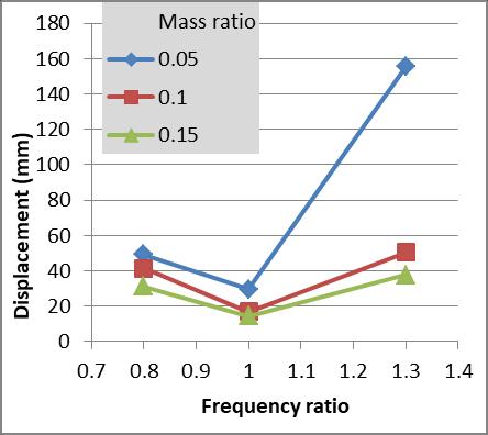
Table -3: MaximumDisplacementofTopFloor(mm)(PTMDPosition2ndFloor)(1.2Hzbaseexcitation)
μ fr
0.05 0.1 0.15 0.8 49.32 41.54 31.13 1 29.65 16.82 14.38 1.3 124 50.38 37.78
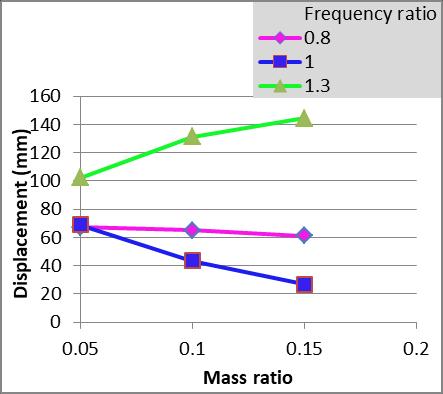
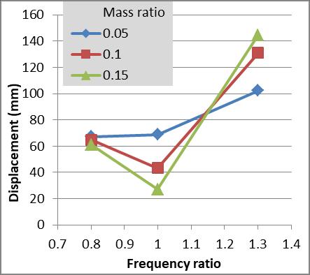
Table -4: MaximumDisplacementofTopFloor(mm)(PTMDPosition1stFloor)(1.2Hzbaseexcitation)
μ fr
0.05 0.1 0.15
0.8 67.12 64.92 61.05 1 68.88 43.34 27.02 1.3 102.2 131.1 144.4
Volume: 09 Issue: 10 | Oct 2022 www.irjet.net p-ISSN: 2395-0072 © 2022, IRJET | Impact Factor value: 7.529 | ISO 9001:2008 Certified Journal |
International Research Journal of Engineering and Technology (IRJET) e-ISSN: 2395-0056
Table -5: MaximumDisplacementof2ndFloor(mm)(PTMDPosition3rdFloor)(4Hzbaseexcitation)
μ fr
0.05 0.1 0.15
0.8 14.36 13.99 12.86 1 13.83 13.38 12.71 1.3 14.01 13.73 12.48
Table -6: MaximumDisplacementofTopFloor(mm)(PTMDPosition2ndFloor)(4Hzbaseexcitation)
μ fr
0.05 0.1 0.15 0.8 18.23 16.39 15.14 1 17.46 16.93 19.93 1.3 18.34 21.41 15.93
Table -7: MaximumDisplacementofTopFloor(mm)(PTMDPosition1stFloor)(4Hzbaseexcitation)
μ fr
0.05 0.1 0.15 0.8 22.01 17.09 16.04 1 16.33 16.03 16.11 1.3 18.5 17.25 16.19
Followingarethegraphsofdisplacementvsfrequencyratioanddisplacementvsmassratio. (a) (b)
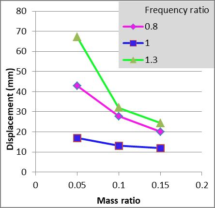
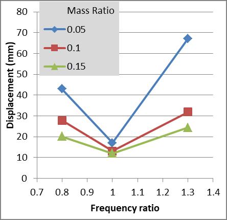
Chart -1: MaximumDisplacementofTopFloor(mm)(PTMDon3rdFloor)(1.2Hzbaseexcitation)
Volume: 09 Issue: 10 | Oct 2022 www.irjet.net p-ISSN: 2395-0072 © 2022, IRJET | Impact Factor value: 7.529 | ISO 9001:2008 Certified Journal | Page28
International Research Journal of Engineering and Technology (IRJET) e-ISSN: 2395-0056
Volume: 09 Issue: 10 | Oct 2022 www.irjet.net p-ISSN: 2395-0072
(a) (b)
Chart -2: MaximumDisplacementofTopFloor(mm)(PTMDon2nd Floor)(1.2Hzbaseexcitation)
(a) (b)
Chart -3: MaximumDisplacementofTopFloor(mm)(PTMDon1st Floor)(1.2Hzbaseexcitation)
(a) (b)
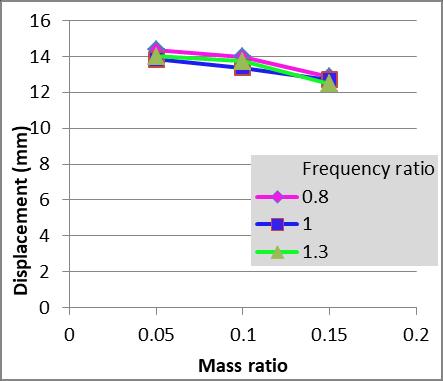
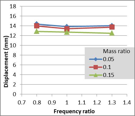
Chart -4: MaximumDisplacementof2nd Floor(mm)(PTMDon3rd Floor)(4Hzbaseexcitation)
2022, IRJET | Impact Factor value: 7.529 | ISO 9001:2008 Certified Journal |
International Research Journal of Engineering and Technology (IRJET) e-ISSN: 2395-0056
(a) (b)
Chart -5: MaximumDisplacementofTopFloor(mm)(PTMDon2nd Floor)(4Hzbaseexcitation)
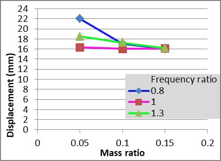
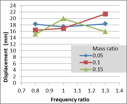
(a) (b)
Chart -6: MaximumDisplacementofTopFloor(mm)(PTMDon1st Floor)(4Hzbaseexcitation)
Following are the graphs of acceleration response of the structure with and without PTMD for 1.2Hz and 4Hz base excitation(PTMDlocatedon3rd floor).
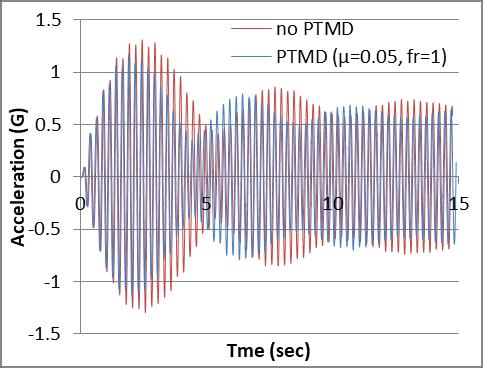
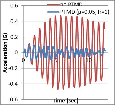
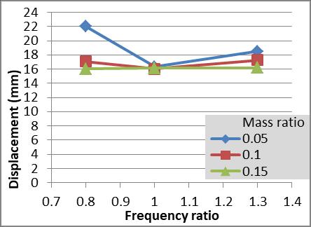
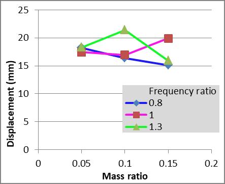
Chart -7: Accelerationresponseof3rd floor
Chart -8: Accelerationresponseof2nd floor withandwithoutPTMD(1.2Hzexcitation) withandwithoutPTMD(4Hzexcitation)
Volume: 09 Issue: 10 | Oct 2022 www.irjet.net p-ISSN: 2395-0072 © 2022, IRJET | Impact Factor value: 7.529 | ISO 9001:2008 Certified Journal | Page30
International Research Journal of Engineering and Technology (IRJET) e-ISSN: 2395-0056
Volume: 09 Issue: 10 | Oct 2022 www.irjet.net p-ISSN: 2395-0072
At1.2Hzexcitationfrequencyresonancewasobserved,hencethePTMDwastunedforthisfrequency.Fromtheresultsitis observedthatwhenthePTMDfrequencyratioof1issuspendedfromthe3rdfloor,significantreductionintheresponseofthe structureoccursforthe1.2Hzbaseexcitationsasshowninchart7.Thisisbecauseforthemodeshapeat1.2Hzbaseexcitation, themaximumamplitudeofvibrationoccursonthe3rd floorandasstatedearlier,thePTMDshouldbesuspendedfromthe pointofmaximumamplitudeforoptimalresults.AlsoduetoPTMD,resonancewaspreventedandasteadystateresponseof thestructurewasachieved.ThePTMDsuspendedfromthe3rd floorhavingμ=0.05,fr=1gives78.4%reductioninmaximum displacement.Thereductioninmaximumdisplacementiscalculatedfromfollowingequation.
%Reductionindisplacement= ˟100
FromChart1(a)itisobservedthatfr=1givesthebestresults.Whenincreasingordecreasingthefrequencyratiofrom1,it makesPTMDlesseffectiveinreducingthedisplacementfor1.2Hzexcitation.
FromdisplacementvsmassratiodataitisobservedthatIncreasingmassratiofrom0.05to0.1givessomeimprovementin reducingthemaximumdisplacement.Butincreasingmassratiofrom0.1to0.15,givesonlyaslightimprovementinreducing themaximumdisplacement.
Forthetestswithbaseexcitationfrequencyof4Hz,changingthefrequencyratiofrom0.8to1andfrom1to1.3doesnot provideanysignificantdifferenceinreducingthemaximumdisplacement.Andwhenthemassratioischangedfrom0.5to0.15, onlya slightimprovementisobservedin reducing the maximumdisplacement. ThePTMDwith μ=0.05,fr=1gives26.7% reductioninmaximumdisplacement.
PTMD location 2nd floor
PTMDsuspendedfrom2ndfloorislesseffectiveatdisplacementreductionthanPTMDpositionedon3rdfloorfor1.2Hzbase excitation.For1.2HzexcitationandPTMDon2nd floor,frequencyratioof1isbetterthanfrequencyratioof0.8and1.3.And reducingthefrequencyratiofrom1makesPTMDlesseffective.AlsoworstcaseoccurswhenPTMDhasμ=0.05,fr=1.3,Forthis caseThemaximumdisplacementobserved is124mm whichisgreaterthanthemaximumdisplacementof the structure without the PTMD. Forthis case,resonance ofthestructureisobserved for 1.2Hz excitation, whichisfarworse than the structurewithoutPTMD.Forthiscase,increasingthemassratioto0.1givessomeimprovement.
Steadystateresponseisobservedfor1.2HzexcitationwhenPTMDshasfrequencyratioof0.8and1.Forthesecases,when increasing mass ratio from 0.05 to 0.1, a slight improvement is observed in reducing the maximum displacement. Also increasingmassratiofrom0.1to0.15providednegligibleimprovement.
ConsideringthePTMDwithμ=0.15,fr=1,for4Hzbaseexcitation,themaximumdisplacementwasmorethanthemaximum displacementofthestructurewithoutPTMD.ChangingthePTMDparametersdidnotprovideanysignificantimprovement.
The PTMD suspended from 1st floor was observed to have the worst performance. When the frequency ratio is 1.3, resonanceofthestructureisobservedfor1.2HzexcitationandthemaximumdisplacementswithPTMDaremorethanthe maximumdisplacementofstructurewithoutPTMD,alsoincreasingthemassratioworsentheperformancewhenfr=1.3.When frequencyratiois1,increasingthemassratiohelpsinreducingthemaximumdisplacement.
For4Hzbaseexcitation,thePTMDdoesnotprovideeffectiveresultsandthemaximumdisplacementofstructurewith PTMDforseveralcombinationsofparametersismorethanthemaximumdisplacementofstructurewithoutPTMD.
A3storiedstructurewastestedforharmonicbaseexcitationshavingfrequency1.2Hzand4Hz.PTMDwasprovidedonthe structurehavingdifferentparametersanddifferentpositions,thedisplacementofthestructurewascalculatedfrommeasured data and performance of PTMD in reducing the maximum displacement was determined and compared for different parameters.Followingconclusionscanbemadefromtheobservations.
1. ThePTMDwhichistunedforthespecificfrequencywasparticularlyeffectiveatloweringtheresponseofthestructure whentheexcitationisprovidedatthatspecificfrequency.
2. PTMDsuspendedfromthe3rd(top)floorproducedthebestresultsinloweringthedisplacementofthestructureand avoidingresonancefor1.2Hzbaseexcitation.
International Research Journal of Engineering and Technology (IRJET) e-ISSN: 2395-0056
Volume: 09 Issue: 10 | Oct 2022 www.irjet.net p-ISSN: 2395-0072
3. TheeffectivenessofPTMDonthesecond(middle)floorwasinferiortothatofPTMDonthetopfloorinminimizingthe structuralresponse.Furthermore,whenPTMDwasgivenafrequencyratioof1.3,resonanceofthestructurewas observed,and the maximumdisplacement ofstructure withPTMDwasgreater thanthe maximumdisplacement withoutPTMD.
4. When PTMD was provided on the 1st (bottom) floor, it was ineffective at reducing the response of the structure. Additionally,resonanceofthestructurewasobservedforamajorityofparametercombinations,andthemaximum displacementofstructurewithPTMDwasmuchgreaterthanthedisplacementofthestructurewithoutPTMD.
5. For4Hzbaseexcitation,PTMDlocatedontopfloorprovidessomereductioninthemaximumdisplacementofthe structure.PTMDlocatedon2nd floorand1st floorhavelittletonoeffectinreducingtheresponsefor4Hzexcitation. Andinsomecasescanincreasethedisplacementofthestructure.
[1] Abburu and S.a.S. - Vibration Control in High-Rise Buildings for Multi-Hazard”, 2015.Master's Thesis, Civil and EnvironmentalEngineering,LSU,BatonRouge,Louisiana,1991.
[2] Connor,J.J.(2003).Structuralmotioncontrol(p.220).PearsonEducation,Inc.
[3] Murty,C.V.R.,etal.-Earthquakebehaviourofbuildings,GujaratStateDisasterManagementAuthority,Gandhinagar 53(2012):79.
[4] HassaniS,AminafsharM.Optimizationofpendulumtunedmassdamperintallbuildingunderhorizontalearthquake excitation.Bull.laSociétéR.desSci.Liège[Enligne].2016Jan1;85:514-31.
[5] Frahm,H,1909-DeviceforDampingVibrationsofBodies,U.S.PatentNo.989958
[6] J.P.(JacobPieter)DenHartog-Mechanicalvibrations,McGraw-Hill,NewYork,1956,(OCoLC)597567130.\
[7] Poon,DennisC.K.,ShawnShieh,LeonardMartinJosephandChing-ChangChang-StructuralDesignofTaipei101,the World'sTallestBuilding,2004.
[8] Elias,S.,&Matsagar,V. (2015).Optimumtunedmass damperforwindand earthquakeresponsecontrol of highrisebuilding.InAdvancesinstructuralengineering(pp.1475-1487).Springer,NewDelhi.
[9] Meirovitch,L.(1986).Elementsofvibrationanalysis.Singapore:McGraw-Hill.
[10]Shrinivas Hebbar A, Shrinidhi D Kulal, Tajmul Pasha, Prasanta Kumar Samal, K Gourav, 2019, Numerical and Experimental Investigation of Vibration Isolation of Three-storied Building Structure using Tuned Mass Damper, InternationalJournalofRecentTechnologyandEngineering(IJRTE),Volume-8Issue-1S2,May2019.
[11]Abubakar, I. & Farid, B.. (2009). “Generalized Den Hartog tuned mass damper system for control of vibrations in structures”.EarthquakeResistantEngineeringStructures.104.185-193.10.2495/ERES090171.
[12]Liu,Y.,Wang,K.,Mercan,O.,Chen,H.,&Tan,P.(2020).Experimentalandnumericalstudiesontheoptimaldesign oftunedmassdampersforvibrationcontrolofhigh-risestructures.EngineeringStructures,211,110486.
[13]Colherinhas,G.B.,deMorais,M.V.,Shzu,M.A.,&Avila,S.M.(2019).Optimalpendulumtunedmassdamperdesign applied to high towers using genetic algorithms: Two-DOF modeling. International Journal of Structural Stability andDynamics,19(10),1950125.
[14]Gerges, R. R., & Vickery, B. J. (2005). Optimum design of pendulum‐type tuned mass dampers. The Structural DesignofTallandSpecialBuildings,14(4),353-368.
[15]Júnior,P.L.B.,deMorais,M.V.,&Avila,S.M.(2019,October).ExperimentalStudyofanInvertedPendulumTuned MassDamper.In25thInternationalCongressofMechanicalEngineering.
International Research Journal of Engineering and Technology (IRJET) e-ISSN: 2395-0056 Volume: 09 Issue: 10 | Oct 2022 www.irjet.net p-ISSN: 2395-0072
[16]Jay Suthar, P.V. Muley, Dr. A. S. Radke, 2020, Experimentally Determining Optimal Mass and Frequency of PendulumTypeTunedMassDamper,InternationalJournalofInnovativeresearchinTechnology,Volume9,Issue 4.
[17]Kang,Y.J.,Peng,L.Y.,Pan,P.,Xiao,G.Q.,&Wang,H.S.(2021).Shakingtabletestandnumericalanalysisofacoalfired power plant equipped with large mass ratio multiple tuned mass damper (LMTMD). Journal of Building Engineering,43,102852.
2022, IRJET | Impact Factor value: 7.529 | ISO 9001:2008 Certified Journal | Page33