International Research Journal of Engineering and Technology (IRJET)
e-ISSN: 2395-0056
Volume: 08 Issue: 08 | Aug 2021
p-ISSN: 2395-0072
www.irjet.net
Analysis of Thermo-Acoustic Refrigeration System Vraj S. Shah1, Ankit K. Parekh2, Kush T. Pandya3, Meet R. Bhavsar4, Dr. Ragesh G. Kapadia5 1-4UG student, Department of Mechanical Engineering, L. D. College of Engineering, Ahmedabad, Gujarat, India
5Professor, Department of Mechanical Engineering, L. D. College of Engineering, Ahmedabad, Gujarat, India ---------------------------------------------------------------------***----------------------------------------------------------------------
Abstract - Thermoacoustic deals with the study of the
inter relationship between heat and sound. A Thermoacoustic refrigerator is an arrangement that brings out the effect of cooling by means of using high intensity sound waves. The sound waves of high intensity are regarded to be pressure pulsations. These pressure pulsations come in proximity with the stack material that is situated inside a resonator tube. The sound waves travel inside the resonator tube leading to the formation of standing wave. The interaction between the original wave and the wave reflected back causes compression and rarefaction of the sound waves. This precipitates the heat transfer across both ends of the stack. By the usage of proper heat exchangers on either side of the stack, the lower temperature obtained can be used to attain the required refrigeration effect.
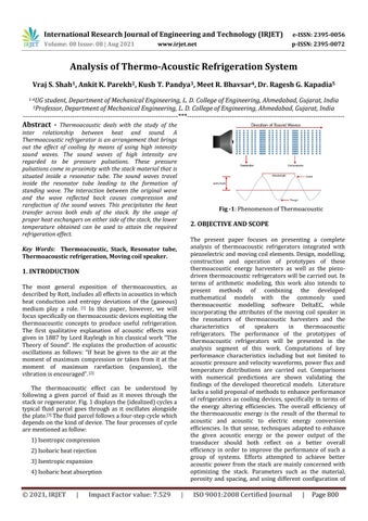
Fig -1: Phenomenon of Thermoacoustic
2. OBJECTIVE AND SCOPE The present paper focuses on presenting a complete analysis of thermoacoustic refrigerators integrated with piezoelectric and moving coil elements. Design, modelling, construction and operation of prototypes of these thermoacoustic energy harvesters as well as the piezodriven thermoacoustic refrigerators will be carried out. In terms of arithmetic modeling, this work also intends to present methods of combining the developed mathematical models with the commonly used thermoacoustic modelling software DeltaEC, while incorporating the attributes of the moving coil speaker in the resonators of thermoacoustic harvesters and the characteristics of speakers in thermoacoustic refrigerators. The performance of the prototypes of thermoacoustic refrigerators will be presented in the analysis segment of this work. Computations of key performance characteristics including but not limited to acoustic pressure and velocity waveforms, power flux and temperature distributions are carried out. Comparisons with numerical predictions are shown validating the findings of the developed theoretical models. Literature lacks a solid proposal of methods to enhance performance of refrigerators as cooling devices, specifically in terms of the energy altering efficiencies. The overall efficiency of the thermoacoustic energy is the result of the thermal to acoustic and acoustic to electric energy conversion efficiencies. In that sense, techniques adapted to enhance the given acoustic energy or the power output of the transducer should both reflect on a better overall efficiency in order to improve the performance of such a group of systems. Efforts attempted to achieve better acoustic power from the stack are mainly concerned with optimizing the stack. Parameters such as the material, porosity and spacing, and using different configuration of
Key Words: Thermoacoustic, Stack, Resonator tube, Thermoacoustic refrigeration, Moving coil speaker.
1. INTRODUCTION The most general exposition of thermoacoustics, as described by Rott, includes all effects in acoustics in which heat conduction and entropy deviations of the (gaseous) medium play a role. [1] In this paper, however, we will focus specifically on thermoacoustic devices exploiting the thermoacoustic concepts to produce useful refrigeration. The first qualitative explanation of acoustic effects was given in 1887 by Lord Rayleigh in his classical work “The Theory of Sound”. He explains the production of acoustic oscillations as follows: “If heat be given to the air at the moment of maximum compression or taken from it at the moment of maximum rarefaction (expansion), the vibration is encouraged”. [2] The thermoacoustic effect can be understood by following a given parcel of fluid as it moves through the stack or regenerator. Fig. 1 displays the (idealized) cycles a typical fluid parcel goes through as it oscillates alongside the plate.[3] The fluid parcel follows a four-step cycle which depends on the kind of device. The four processes of cycle are mentioned as follow: 1) Isentropic compression 2) Isobaric heat rejection 3) Isentropic expansion 4) Isobaric heat absorption
© 2021, IRJET
|
Impact Factor value: 7.529
|
ISO 9001:2008 Certified Journal
|
Page 800
International Research Journal of Engineering and Technology (IRJET)
e-ISSN: 2395-0056
Volume: 08 Issue: 08 | Aug 2021
p-ISSN: 2395-0072
www.irjet.net
stack such as parallel plates, pin arrays and circular pores and/or changing the tube form and aspect ratio. This, however, results in a system that optimally performs at specific frequencies, exclusively regulated by the tube dimensions and the transducer parameters in order to satisfy the impedance matching condition. [4]
Thermocouple Grade: 0 to Thermocouple
3.2 PARAMETERS Table -3: Thermo physical properties of Helium [5]
3. COMPONENTS AND PARAMETERS
Parameters (Helium)
3.1 COMPONENTS Table -1: Components and their materials Components
150 C
Materials
Specification
Speed of sound in gas
1013 m/s
Gas specific heat
5193 J/KgK
Gas thermal diffusivity
13.2*10-5 m2/s
Acoustic Driver
Piezoelectric
Gas thermal conductivity
0.155 W/mK
Stack
Mylar, Kapton
Gas density
0.8845 Kg/m3
Fluid Tubes: Copper
Ratio of specific heats
1.67
Drive ratio
0.02
Heat exchanger
Housing: Steel
Resonator Tube
Mild steel
Working gas
Air, Helium
4. DESIGN
Electronic Device (Amplifier)
-
4.1 DESIGN STRATERGY
Thermocouple
J type thermocouple
Frequency (50-500 Hz)
The goal in the design of a thermoacoustic refrigerator is to cover the requisites of a given cooling power QC and a given low temperature TC. These requirements are added to the operational variables. The low temperature TC is shown indirectly in the form of Temperature gradient ΔTm. The given table-4 shows the operational variables and working gas properties that are essential to approximate the design of thermoacoustic refrigerator. [6]
Thermal Conductivity
Table -4: Operating and working gas variables
Table -2: Components and their specifications Components
Specifications
Acoustic Driver
(Mylar-0.15 W/m-K)
Stack
Operational Variables
Diameter: 50-100mm
Heat exchanger
Length: 50-160mm
Operational frequency f
Dynamic viscosity μ
Length:100mm
Average pressure PM
Thermal conductivity K
Dynamic pressure amplitude PO
Sound velocity a
Mean temperature TM
Ratio of isobaric to isochoric specific heat ɣ
Temperature gradient ΔTM
Specific heat CP
Mach Number M
Gas density ρ
Drive Ratio D
Prandtl number σ
Large dia.: 103mm Small dia.:56mm
Resonator Tube
Resonator length: 7001400mm Prandtl Number (20 C) =
Working gas
(Air=0.72, Helium=0.687) Electronic Device (Amplifier)
© 2021, IRJET
|
Working gas properties
Power output: 20 watts
Impact Factor value: 7.529
|
ISO 9001:2008 Certified Journal
|
Page 801
International Research Journal of Engineering and Technology (IRJET)
e-ISSN: 2395-0056
Volume: 08 Issue: 08 | Aug 2021
p-ISSN: 2395-0072
www.irjet.net
PM, the sound velocity 'a' and the cross-sectional area of the stack,
Cooling power QC
4.2 ASSUMPTION 1. The thermal conduction (i.e., heat leak from cold side to heated side) along both the sides of stack and the gas trapped in the stack is neglected. 2. The stack is relatively short to the wavelength of the acoustic standing wave. 3. The difference of temperature across the stack is a small fraction of the mean temperature of the stack and gas. 4. The heat and work flow are steady state. 5. The boundary layer viscosity is assumed to be zero. 6. The resonator pressure remains almost constant inside it.[7]
It is also used as a dimensionless parameter for the geometry of the stack. It is taken as 0.75. The thermal and viscous penetration depths are given by,
Where, k is the thermal conductivity, µ is the viscosity, ρ is the density, Cp is the isobaric specific heat of the gas, and ω is the angular frequency of the sound wave. These resultant normalized parameters are given an extra index n. [10]
4.3 DESIGN PROCEDURE A total of 5 basic components are to be designed of which stack is the most important. It is the most critical component when it comes to the functioning of the thermo acoustic refrigerator, as well as it has a determining effect on the design and orientating of all remaining components. Initially, to begin with the design of the stack, first the values of all parameters are required to be obtained and finalized. Sometimes direct values of some parameters are not available. Values at particular temperatures are accurately available and using pertinent formulae, the values at operating temperatures can be calculated. The temperature difference ΔTM is indicative of the range of temperatures within which the system is going to be functioning. Given the lowest temperature TC on cold side and the highest TH at hot end one can obtain the operating temperature range which is nothing but ΔTM. [8]
4.4 APPROXIMATED PROTOTYPE [CAD MODEL]
Fig -2: Prototype approximation
5. ANALYSIS AND RESULTS
4.4 FREQUENCY
5.1 THEORETICAL ANALYSIS
As the power in the thermoacoustic device is a linear function of the acoustic resonance frequency, an obvious choice is thus a high resonance frequency. On the other hand, K is inversely proportional to the square root of the frequency which again implies the very small plate spacing of stack plates. Making a compromise between these two effects and the fact that the driver resonance has to be maintained to the resonator resonance for high efficiency of the driver, the frequency of 267Hz was chosen. [9]
DeltaEC numerically integrate momentum, continuity and energy equation. We iterated few geometric and thermo physical parameter that affected thermo acoustic in DeltaEC software which are as follows: Various parameters that are required for input in DeltaEC are: Mean P: It indicates the charging pressure inside the resonating tube. Frequency: It is the frequency of our acoustic source. It is measured in Hertz. TBeg: TBeg is short form for Temperature at beginning. Its value generally is equal to the value of surrounding. |p|: It is the dynamic pressure which is a function of amplitude of acoustic source. Ph |p|: It shows the phase of dynamic pressure. |U|: Flow rate in (m3/s). Ph |U|: It shows the phase of flow rate. Flow rate and its phase both are kept as guesses in DeltaEC
4.5 STACK DESIGN The stack was designed and normalization of parameters is carried out to aid simplification. The length and position of the stack can be normalized by 2. The thermal and viscous penetration depths can be normalized by the half spacing in the stack y0. The cold temperature or the temperature difference can be normalized by TM. Since thermal conductivity k and volume v are related by Prandtl number, this will further simplify the number of parameters. The acoustic power W and the cooling power QC can be normalized by the product of the mean pressure
© 2021, IRJET
|
Impact Factor value: 7.529
|
ISO 9001:2008 Certified Journal
|
Page 802
International Research Journal of Engineering and Technology (IRJET)
e-ISSN: 2395-0056
Volume: 08 Issue: 08 | Aug 2021
p-ISSN: 2395-0072
www.irjet.net
s we cannot determine its value practically or theoretically. Various geometric parameters which go into determining the design of thermoacoustic refrigerator are: L1: Length of duct between acoustic driver and stack. Ls: Length of stack. L3: Length of duct after stack. Lc: Length of cold heat exchanger. Lh: Length of hot heat exchanger. A1: Area of duct between acoustic driver and stack. As: Area of stack. A3: Area of duct after stack. Ac: Area of cold heat exchanger. Ah: Area of hot heat exchanger. y0: Distance between two layers of stack.
Table -5: Geometrical and Thermophysical parameter Input Iteration 1 Iteration 2 Iteration 3 Parameters Mean P (Pa) 7 E+05 5E+05 8E+05 Frequency (Hz) 300 200 100 TBeg (K) 300 300 300 Gas Helium Air Helium Stack material Mylar Kapton Mylar L1 (m) 0.1778 0.1778 0.1778 Ls(m) 7E-02 3.5E-02 0.12 L3 (m) 3.5E-02 3.5E-02 3.5E-02 Lc (m) 1E-03 1E-03 1E-02 Lh (m) 1E-03 1E-03 1E-02 2 A1 (m ) 3.8E-04 3.8E-04 3.8E-04 As (m2) 4.5E-04 3.8E-04 4.5E-04 A3 (m2) 4.6E-04 3.8E-04 4.6E-04 Ac (m2) 4E-04 4E-04 4E-04 Ah (m2) 4E-04 4E-04 4E-04
Fig -3: Result obtained from result 3 in form of temperature drop
© 2021, IRJET
|
Impact Factor value: 7.529
|
ISO 9001:2008 Certified Journal
|
Page 803
International Research Journal of Engineering and Technology (IRJET)
e-ISSN: 2395-0056
Volume: 08 Issue: 08 | Aug 2021
p-ISSN: 2395-0072
www.irjet.net
2. Stack position from the driver end should be critically optimize to get desired output it should place near the driver end but not exactly at driver end, the results are severe when it is placed and exactly at driver end. The novelty of this investigation in relation to similar ones is that it used materials that are relatively low cost and easily accessible. Such a solution can be generally recommended for the inexpensive thermoacoustic refrigerator designed for the demonstration of the basic physical principles of thermoacoustic phenomenon. Fig -4: Result obtained from result 1 in form of temperature drop
REFERENCES Rott N. Thermoacoustics Adv. Appl. Mech. 1980,20,135-175. [2] Sjoerd W. Reinstraand, Jaap Molenaar, Systematic Derivation of the weakly non-linear theory of thermoacoustic devices 2006. [3] Ajith Krishnan, Jinshah Kalluvilr, Study on a standing wave Thermoacoustic Refrigerator made of Readily Available Materials, 2013. [4] Jakub Kajurek, Arthur Rusowicz, Experimental Investigations on the Thermoacoustic Effect in Easily Accessible Porous Materials, "MDPI, 2020". [5] https://www.engineeringtoolbox.com [6] Thermoacoustic Refrigeration System Setup, "International Journal of Mechanical Engineering and Technology, 2015". [7] A B Desai, K P Desai, H B Naik, M D Atrey, Experimental Study and Analysis of a Thermoacoustically Driven Thermoacoustic Refrigerator. [8] Thermoacoustic Refrigeration System, "International Journal of Advance Research and Development, Vol. 2, Issue 7". [9] M. E. H. Tijani, Design of Thermoacoustic Refrigerator "Elsevier, 2001". [10] Nathan Thomsan Weiland, Ben T. Zinn, "Design of Thermoacoustic Engine in Internal Combustion" March, 2003. [1]
Fig -5: Result obtained from result 2 in form of temperature drop
5.2 RESULTS The temperature drop across two ends of stack was obtained as the result of above codes and corresponding parameters. In the first iteration, a temperature drop upto 293K from 300 was obtained which gives the temperature difference around 7K. In the second iteration, a temperature drop upto 295K from 310K was obtained which gives the temperature difference around 15K. In the third iteration, a temperature drop upto 230K from 300K was obtained which gives the temperature difference around 70K.
BIOGRAPHIES Mr. Vraj S. Shah, is a final year student of Department of Mechanical Engineering, L.D. College of Engineering, Gujarat Technological University.
6. CONCLUSION Different optimization methods both numerical and experimental have employed to get lower temperature along with maximum temperature gradient across the stack region, least input power for producing a cooling effect and finally the coefficient of performance of the system. Several conclusions have drawn based upon past studies in the area of thermoacoustic refrigeration. 1. Thermal penetration depth and stack spacing are critical concerns for stack geometry. The final choice will be a compromise between the manufacturing suitability and thermal penetration depth.
© 2021, IRJET
|
Impact Factor value: 7.529
Mr. Ankit K. Parekh, is a final year student of Department of Mechanical Engineering, L.D. College of Engineering, Gujarat Technological University.
|
ISO 9001:2008 Certified Journal
|
Page 804
International Research Journal of Engineering and Technology (IRJET)
e-ISSN: 2395-0056
Volume: 08 Issue: 08 | Aug 2021
p-ISSN: 2395-0072
www.irjet.net
Mr. Kush T. Pandya, is a final year student of Department of Mechanical Engineering, L.D. College of Engineering, Gujarat Technological University.
Mr. Meet R. Bhavsar, is a final year student of Department of Mechanical Engineering, L.D. College of Engineering, Gujarat Technological University. Dr. Ragesh G. Kapadia, is presently associated with the L.D. College of Engineering, Ahmedabad as a professor in the Mechanical Engineering department.
© 2021, IRJET
|
Impact Factor value: 7.529
|
ISO 9001:2008 Certified Journal
|
Page 805