International Research Journal of Engineering and Technology (IRJET)
e-ISSN: 2395-0056
Volume: 07 Issue: 02 | Feb 2020
p-ISSN: 2395-0072
www.irjet.net
Analysis and Implementation of Active Power Filters Neelam Verma1, Garima Vyas2, Geetanjali Meghwal3, Dr Monika Vardia4 1,2,3,4EE DEPARTMENT GITS,UDAIPUR
----------------------------------------------------------------------***--------------------------------------------------------------------ABSTRACT - Active power filters (APF) are filters, which can perform the job of harmonic elimination. Harmonic, where passive power filters use combinations of resistors (R), inductors (L) and capacitors (C) and does not require an external power source or active components such as transistors. The filter can compensate for harmonic currents, power factor and load unbalance. Together simulation and experimental results are presented, showing that better dynamic and steady-state response can be achieved with this approach. To generate desired APF output voltage by Pulse Width Modulation based on generated reference voltage. Key Words: Active Power Filters (APF), Pulse Width Modulation (PWM), Current Source Inverter (CSI), Voltage Source Inverter (VSI). 1. INTRODUCTION The uses of loads which are not linear in nature and which also vary with time have been continuously increasing in the present time. As a result it causes distortion in current/voltage waveforms and introduces harmonics in it. Ultimately causes poor power factor of power supply. These problems can be eliminated with the help of APF which provides power conditioning. It helps in compensating the reactive power, regulating the voltage and eliminating the harmonics. APF is primarily used for eliminating harmonics on consumer load. The other function is to compensate for voltage imbalance. To distribution system it provides harmonic damping factor.
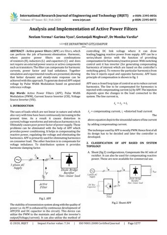
controlling DC link voltage where it can draw leading/lagging reactive power from supply. APF can be a series/shunt device with the function of providing compensation for harmonics/reactive power. With switching control unit it has inverter (for generating compensating harmonics of interest which are based on the controller’s switching gates). To remove the particular harmonics from the line it injects equal and opposite harmonic. APF basic principle of compensation is shown in fig. 1 APF uses a closed loop type of control so as to reduce current harmonics. The line to be compensated for harmonics is injected with compensating current (if) by APF. The injection depends upon the changes in the load connected to the system. The line current is,
is i f il
i f = compensating current, i1 =distorted load current
The
above equation depicts the sinusoidal nature of line current by adding compensating current. The technique used by APF is mostly PWM. Hence first of all its design has to be decided and later the controller is developed. 2. CLASSIFICATION OF APF BASED ON SYSTEM TOPOLOGY A. Shunt (fig.2) configurations, Compensate the AC side of rectifier. It can also be used for compensating reactive power. These are now available for commercial use.
Fig.1. APF The stability of transmission system along with the quality of power i.e. its PF is enhanced by continuous development of APF(VSI and DC capacitor in the circuit). This device can utilize the PWM to the maintain and adjust the inverter’s output(Voltage/current). It can also utilize the method of © 2020, IRJET
|
Impact Factor value: 7.34
|
Fig.2. Shunt APF
ISO 9001:2008 Certified Journal
|
Page 1277
International Research Journal of Engineering and Technology (IRJET)
e-ISSN: 2395-0056
Volume: 07 Issue: 02 | Feb 2020
p-ISSN: 2395-0072
www.irjet.net
B. Series (fig.3) configurations, It is used in general for the diode rectifier with a dc link capacitor which is the voltage harmonic source. It can be used in regulating voltage. Its use is limited to the laboratory.
Fig .5 Basic topology of a voltage source inverter B. CURRENT SOURCE INVERTER (CSI) The DC current always flow in one direction in it. The power is reversed by reversing the DC side voltage. Fig.3. Series APF C.
Hybrid active-passive power filter (HAPF, fig.4). To perform better it is the combination of passive and active filter. The use of LC tuned filter eliminates the additional use of switching-ripple filter because it does the function of filter for harmonics as well as switching-ripple.
Fig. 6 Basic topology of current source inverter IV.
Fig.4. Hybrid active power filter III. CLASSIFICATION BASED ON CONVERTER There are basically two types of it based on the mentioned criterion, A. Voltage source inverter (VSI) B.
A. VOLTAGE SOURCE INVERTER (VSI) In it the DC side voltage has only one polarity (unipolar) and by reversing the polarity of Direct current power is reversed in it.
|
Impact Factor value: 7.34
In the recent times the development in the field of solid state devices has grown rapidly. Hence the use of devices like microprocessors in the industrial application is becoming more common. To be specific these are utilized in the power converters for the purpose of switching which supplies the load or motor. The switching power received by the motor/load is controlled with the use of PWM. Power transistors used in converters are switched by receiving PWM pulses at their gate. The frequency and amplitude of these pulses are fixed. These are in the form of train but with variable width. For every period of PWM there is one pulse which has fixed magnitude. On application of these pulses on gates of power transistor, the power transistors turns on which changes the PWM period based on the same signal for modulation As compared to linear power amplifier its merits are, Lower power dissipation
Current source inverter (CSI)
© 2020, IRJET
MODELLING OF PWM TECHNIQUE WITH APF
|
1.
Easy implementation and controlling
2.
Temperature variation is nil and aging-cause
3.
Compatible with micro-processors
ISO 9001:2008 Certified Journal
|
Page 1278
International Research Journal of Engineering and Technology (IRJET)
e-ISSN: 2395-0056
Volume: 07 Issue: 02 | Feb 2020
p-ISSN: 2395-0072
www.irjet.net
(c) Output load current waveform Fig. 7.2. Waveform of 3Φ balance RL-load with no APF. Fig.4.1 Symmetric and asymmetric PWM signals V.
The above waveforms are of Phase A before compensation.
SIMULATION RESULT AND ANALYSIS
The fig 7.1 along with fig. 7.19 displays the APF model with different loads. The simulation models shown uses the 230V as input supply which is the RMS value of voltage and 5kHz as switching frequency before and after balancing of power. CASE 1: LINEAR LOAD Case 1.1: Balance RL load with no APF
(a) Load current harmonic spectrum
phase-A Input source current harmonic spectrum
Fig.7.1 3Φ balance RL-load with no APF
(b) Source current harmonic spectrum Fig. 7.3 linear balance load’s Harmonic spectrum with no APF for Phase-A The spectrum shown above of harmonics is for Phase A before Case 1.2: PWM Technique for Linear balance RL load with APF
(a) Input RMS source voltage waveform
(b)Input source current waveform Fig. 7.4 PWM Technique for Linear balance RL load with APF
© 2020, IRJET
|
Impact Factor value: 7.34
|
ISO 9001:2008 Certified Journal
|
Page 1279
International Research Journal of Engineering and Technology (IRJET)
e-ISSN: 2395-0056
Volume: 07 Issue: 02 | Feb 2020
p-ISSN: 2395-0072
www.irjet.net
(a) Load current
(b) Input source current Fig.7.6 PWM technique for linear balance RL load with APF’s harmonic spectrum The harmonic spectrum shown above is after applying the compensation by APF with PWM. Case 1.4: Linear unbalance RL load with no APF
(b) Input source current Fig.7.5 waveform of PWM Technique for Linear balance RL load with APF The waveform shown above for the current is after applying the compensation by APF with PWM.
Fig. 7.10 3Φ unbalances RL-load condition without APF
(a) Output load current (a) Output load current
(b) Input source Current Fig. 7.11 3Φ unbalances RL-load with no APF’s waveform The above waveforms are before compensation.
© 2020, IRJET
|
Impact Factor value: 7.34
|
ISO 9001:2008 Certified Journal
|
Page 1280
International Research Journal of Engineering and Technology (IRJET)
e-ISSN: 2395-0056
Volume: 07 Issue: 02 | Feb 2020
p-ISSN: 2395-0072
www.irjet.net
(b) input source load Current Fig.7.14 PWM technique for Linear unbalance RL load with APF’s waveforms The above waveforms shown are obtained after applying compensation by the APF with PWM (a) Output load current
Input source current harmonic spectrum
phase-A Output load current harmonic spectrum of PWM technique with APF
(b) Input source current Fig.7.12 3Φ unbalances RL-load with no APF’s Harmonic spectrum
(a) Output load current
The above Harmonic spectrums are before compensation Case 1.5: PWM technique for Linear unbalances RL load with APF For Unbalance load load FFT
Input source current harmonic spectrum
(b). Input source current Fig. 7.13 PWM technique for linear unbalance RL load with APF
Fig.7.15 PWM technique for linear unbalance RL load with APF’s Harmonic spectrums The above Harmonic spectrums shown are obtained after applying compensation by the APF with PWM.
(a) Output load current
© 2020, IRJET
|
Impact Factor value: 7.34
|
ISO 9001:2008 Certified Journal
|
Page 1281
International Research Journal of Engineering and Technology (IRJET)
e-ISSN: 2395-0056
Volume: 07 Issue: 02 | Feb 2020
p-ISSN: 2395-0072
www.irjet.net
Case 2.2: PWM Technique for Nonlinear R load with APF
Input source current spectrum
(b) Input source current Fig. 7.22 PWM technique for nonlinear R load with APF
Fig.7.24 PWM technique for nonlinear R load with APF’s harmonic spectrum The harmonic spectrums shown above have been obtained after applying the compensation by APF with PWM. VI. CONCLUSION The problem of current harmonics in distribution system can be reduced effectively by the use of APF. On the platform of MATLAB/Simulink a balanced non linear load is provided with 3 phase APF. The power system's power factor is improved by using PWM with the reduction of current harmonics by hybrid APF.
(a) Output load current
The current ripple reduction is achieved by PWM. VII. REFERENCES
(b) Input source current Fig.7.23 PWM Technique for Nonlinear R load with APF’s waveform The waveforms shown above have been obtained after applying the compensation by APF with PWM.
1. He, Jinwei; Beihua Liang; Yun Wei Li; Chengshan Wang (7 June 2016). "Simultaneous Microgrid Voltage and Current Harmonics Compensation Using Coordinated Control of Dual-Interfacing Converters". IEEE Transactions on Power Electronics. 2. Jain, S. K.; P. Agrawal; H. O. Gupta (10 December 2002). "Fuzzy logic controlled shunt active power filter for power quality improvement". 3. Hirak Patangia, Sri Nikhil Gupta Gourisetti, "A Harmonically Superior Modulator with Wide Baseband and Real-Time Tunability", IEEE International Symposium on Electronic Design (ISED), India, Dec.11
Output load current harmonics specrtrom
4. Hirak Patangia, Sri Nikhil Gupta Gourisetti, “A Novel Strategy for Selective Harmonic Elimination Based on a Sine-Sine PWM Model”, MWSCAS, U.S.A, Aug 2012.
a
(a) Output load current
© 2020, IRJET
|
Impact Factor value: 7.34
|
ISO 9001:2008 Certified Journal
|
Page 1282