INTERNATIONAL RESEARCH JOURNAL OF ENGINEERING AND TECHNOLOGY (IRJET)
E-ISSN: 2395-0056
VOLUME: 07 ISSUE: 01 | JAN 2020
P-ISSN: 2395-0072
WWW.IRJET.NET
IMPROVING THE FUEL ECONOMY AND REDUCING THE EMISSION OF FOUR STROKE DIESEL ENGINE BY THE PROCESS OF FUEL IONIZATION Punitharani K1, R. Haresh2, R. Jaiphin Prabhu3, M.K Murugan4 1Faculty, Department of Mechanical Engineering, PSG College of Technology, Coimbatore, Tamil nadu, India.
2,3,4UG student, Department of Mechanical Engineering, PSG College of Technology, Coimbatore, Tamil nadu, India.
-----------------------------------------------------------------------***----------------------------------------------------------------------
Abstract—Vehicles on road produces large amount of CO, HC and NOx etc. as an exhaust emission. These are produced as a result of incomplete combustion of fuels in IC engine. The emission control methods like exhaust gas recirculation which reduces the formation of NOx and the catalytic converter is a device placed in the exhaust pipe, which converts hydrocarbons, carbon monoxide, and NOx into less harmful gases by using a combination of platinum, palladium and rhodium as catalysts. In addition to these methods the authors incorporated a novel method named magnetic fuel ionization which was proved to be promising in enhancing the performance and reducing emission levels in diesel engines. So, the electro-magnetic field is used to ionize the fuel in this thesis. Two-third of the heat is wasted as exhaust gas and in this thesis a turbine is used for waste heat recovery. The current required for ionizing the fuel is generated by a turbine and is stored in a 12 V battery. Ionizing the fuel favors complete combustion in diesel engine. Thus, NOx emission is reduced and fuel economy is improved.
ionization is a new technology similar to the others which helps in achieving complete combustion.
In this work, study of electromagnetic circuit and electricity generation from turbine, followed by fabrication of electromagnetic circuit and turbine is done. Then the experiment is carried out using the setup which in-turn reduces emission and improves fuel economy.
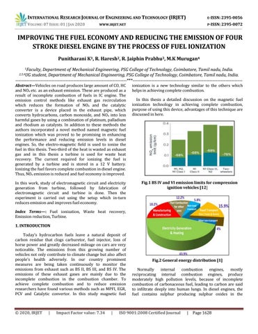
Fig.1 BS IV and VI emission limits for compression ignition vehicles [12]
In this thesis a detailed discussion on the magnetic fuel ionization technology in achieving complete combustion, purpose of using this device, advantages of this technique are discussed in here.
Index Terms—: Fuel ionization, Waste heat recovery, Emission reduction, Turbine. 1. INTRODUCTION Today’s hydrocarbon fuels leave a natural deposit of carbon residue that clogs carburetor, fuel injector, loss of horse power and greatly decreased mileage on cars are very noticeable. The emissions from this growing number of vehicles not only contribute to climate change but also affect people’s health adversely. In our country prominent measures are being taken continuously to monitor the emissions from exhaust such as BS II, BS III, and BS IV. The emissions of these exhaust gases are mainly due to the incomplete combustion in the combustion chamber. To achieve complete combustion and to reduce emission researchers have found various methods such as MPFI, EGR, PCV and Catalytic convertor. In this study magnetic fuel
© 2020, IRJET
|
Impact Factor value: 7.34
|
Fig.2 General energy distribution [1] Normally internal combustion engines, mostly reciprocating internal combustion engines, produce moderately high pollution levels, because of incomplete combustion of carbonaceous fuel, leading to carbon are said to infiltrate deeply into human lungs. In diesel engines, the fuel contains sulphur producing sulphur oxides in the
ISO 9001:2008 Certified Journal
|
Page 1628
INTERNATIONAL RESEARCH JOURNAL OF ENGINEERING AND TECHNOLOGY (IRJET)
E-ISSN: 2395-0056
VOLUME: 07 ISSUE: 01 | JAN 2020
WWW.IRJET.NET
P-ISSN: 2395-0072
exhaust, leading to acid rain. The high temperature of combustion creates larger proportions of nitrogen oxides (NO), and are demonstrated to be harmful to both animal and plant health. The emission control methods like exhaust gas recirculation(EGR) which decreases the formation of NOx and the catalytic converter is a device placed in the exhaust pipe, which converts carbon monoxide, hydrocarbons, and NOx into less harmful gases by using a combination of palladium, platinum and rhodium as catalysts. In consideration of the above essential problems in diesel engines, a new technique named magnetic fuel ionization was evidenced to be encouraging in improving the performance and reducing the emission levels in the diesel engines.
gasoline and Diesel with gases and, hence it must be considered in the future for transport purpose.
Nowadays technology is growing at a very faster rate. The conventional energy resources like gasoline, Diesel etc. are on an edge of annihilation. So researchers are moving towards the use of non-conventional energy sources and it also requires certain kind of energy to convert it into alternative form. In this thesis we are utilizing the kinetic energy of exhaust gases of the vehicle which is lost as waste heat. 2. OBJECTIVES To reduce the emission of exhaust gases such as NOx, CO, HC By the process of magnetic fuel ionization the exhaust gas emissions such as particulate matter, NOx, CO can be reduced. To increase the fuel economy When the fuel is ionized by the magnetic field, the molecules are realigned before entering into the combustion chamber. Therefore, the fuel does not escape as flue gases. By this technique the fuel economy can be increased. To utilize the waste heat rejected by the automobile into electricity using a turbine setup in the exhaust manifold In automobile maximum amount of heat is rejected as waste in exhaust gas, a turbine setup is kept near the exhaust so that the turbine is rotated by the exhaust gases which converts mechanical energy into electric energy and it is stored in a battery. 3. LITERATURE SURVEY The electric Hussain H. Al-Kayiem et al in 2017 [1] conducted a survey of fuel magnetization in internal combustion engines to reduce the emissions and to refine their fuel consumption and their performance. Fuel consumption in the engine (upto 18% in gasoline and 14% in diesel) is decreased because of magnetic treatment of the fuel. The magnetic treatment decreased the emission of HC and CO2 by 70%, NOx by 68% in gasoline engine. Thus, it is found that the magnetic field represents as a good alternative for © 2020, IRJET
|
Impact Factor value: 7.34
|
Sachin Kumar Kore et al in 2015 [2] conducted a study to understand the performance of electromagnetic field which will ensure complete combustion of air-fuel mixture and emission of IC engine. The efficiency of engine increases by adding magnetic field in the path of fuel line. Hence the resultant fuel burns more completely and produces higher engine output and improves fuel economy (increases mileage from 10-30%). Shweta Jain et al in 2012 [4] analyzed that large amount of emission gases were produced because of incomplete combustion and gives lower efficiency in diesel engines. By improving fuel turbulence, the fuel is pumped and burned much more clearly and the premature production of sludge is prevented. 30% extra life for catalytic convertors is provided. It increases mileage about 10-40%. By achieving correct fuel burning parameters through proper magnetic means we can assume that it releases lowest possible level of toxic emissions. Piyush M Patel et al in 2014 [3] conducted an experiment to analyse the performance and emission of single cylinder four stroke diesel engines under the power of producing the effect of magnetic field. It is clear from the experiment result that in both with and without Magnet Fuel Energizer brake thermal efficiency, indicated power are similar but indicated power gets improved at lower load condition. Specific fuel consumption is decreased due to the fuel consumption reduction at higher load. The experiment results shows that the magnetic effect on reduction of fuel consumption was up to 8% at higher load condition. The emission of CO gets reduced at higher load. The effect on NOx emissions reduces up to 27.7%. Y. Al Ali et al in 2012 [5] conducted an experiment to reduce the level of atmospheric pollutions caused by vehicle engine emissions by fuel ionization. Emissions of CO and HC are reduced by 70% and increase of fuel economy by 18%. The Magnetic device is either installed onto the fuel line or inside the fuel tank. Farrag A.El Fatih et al in 2010 [6] investigated the effect of magnetic field on internal combustion engines, concentrated on engine performance parameters such as fuel consumption and exhaust emissions. The fuel is subjected to a permanent magnet mount on fuel inlet lines. The experiments were conducted at different idling engine speeds in a SI engine. The magnetic effect on fuel consumption reduction was upto 15% and CO reduction is upto 7%. No emission reduction was upto 30%.
ISO 9001:2008 Certified Journal
|
Page 1629
INTERNATIONAL RESEARCH JOURNAL OF ENGINEERING AND TECHNOLOGY (IRJET)
E-ISSN: 2395-0056
VOLUME: 07 ISSUE: 01 | JAN 2020
WWW.IRJET.NET
P-ISSN: 2395-0072
Vijay Kumar et al in 2015 [8] used the power from vehicle exhaust to generate the electricity. Two-thirds of the energy from combustion in a vehicle is lost as waste heat, of which 40% is in the form of hot exhaust gas. They placed a turbine in the path of exhaust in the silencer. They also placed an engine in the chassis of the vehicle. The turbine is connected to a dynamo, which is used to generate power. Depending upon the airflow the turbine will start rotating, and then the dynamo will also starts to rotate. The generated power is stored to the battery. The battery power can be consumed for the users comfort. It would also help to recognize the improvement in performance and emissions of the engine if these technologies were adopted by the automotive manufacturers.
adjacent the fuel line. The fuel is in the liquid state when it is in the fuel tank. The fuel molecules will only combust when they are vaporized and mixed with the air. Magnetic field helps to ionize the fuel. The molecules of hydrogen and carbon flowing through a magnetic field change their orientation in the direction opposite to the magnetic field. This results in changes of molecule configuration and weakens the intermolecular force between the molecules. The magnetic field disperses the molecules into more tiny particles and making the fuel less viscous. Every individual molecule consists of many atoms made up of several electrons along with neutrons revolving around their nucleus. During the combustion process, the fuel is not mixed with oxygen vigorously, and the molecules are not realigned. The process of realignment along with ionization of the fuel is accomplished by applying a magnetic field. Magnetic field applied at the fuel line atomize the fuel and which get stick to oxygen and increases air fuel mixing ratio.
Impha.Y.D et al in 2017 [9] modified a stationary diesel engine for producing power using turbine. Substantial thermal energy is available from the exhaust gas in modern automotive engines. Two-thirds of that thermal energy is lost. The nozzle is connected to the exhaust silencer of the engine. When the engine is started, exhaust gas starts flowing through the nozzle. The nozzle is place so that the gases fall directly on the turbine blades. The turbine which is coupled to a dynamo starts rotating and power is generated in the dynamo. The power generated may be stored in a battery of further use. Waste heat recovery entails capturing and reusing the waste heat from internal combustion engine and using it for heating or generating mechanical or electrical work. Shaikh Mobin.A et al in 2017 [11] made a model which produced electric power by using exhaust gas of vehicle specially two wheeler. All forms of energies are required for doing various mechanical operations, but now there is large problem of electricity due to low availability energy resources. In the model, by using kinetic energy of exhaust gas the runner rotates which attach to large gear by using shaft which further attach to small gear, placed on dynamo finally dynamo produces electric power. By using this waste gas of vehicle this model can work better for the electric power generation. This set up is mainly useful for villages. It can be used as power source at night when output power produced by set up is stored in battery. This set up is easy to handle and cheaper.
Fig.3 Molecular arrangement of fuel with magnetic field [4]
Magnetic fuel conditioner
According to Van der Waals force, there exists a strong binding between oxygen and hydrocarbons in oxides of this magnetic field, which helps in the complete combustion of fuel inside the combustion chamber. This results in improved fuel economy and hydrocarbons, carbon monoxide and nitrogen emissions from the exhaust are reduced. The fuel ionization also aids to dissolve the carbon build up in fuel injector, carburetor and combustion chamber, thus keeping the engine in clear condition. According to the equipment of combustion, the magnetic field density which is supposed to be passed onto the fuel fluctuates as well as the rate of combustion. The main aim of the magnetic fuel conditioner is to offer better molecular attraction in diesel and petroleum based fuel so that re-polymerization is more effective.
An electromagnetic fuel conditioner is a device which is used to arrange the fuel molecules and to alter the atomic structure so that complete combustion takes place in engine. In a magnetic fuel conditioner the magnet for producing the magnetic field is oriented so that its north pole is located spaced apart from the fuel line and its south pole is located
An electromagnetic coil is an electrical conductor such as a wire which is in the shape of a spiral, coil or a helix. Greater the turns of wire, the stronger the field will be formed. On the contrary, due to Faraday’s law of induction, a change in external magnetic flux induces a voltage in a conductor such as wire.
4. PRINCIPLE AND WORKING OF SETUP
© 2020, IRJET
|
ELECTROMAGNETIC
Impact Factor value: 7.34
|
ISO 9001:2008 Certified Journal
|
Page 1630
INTERNATIONAL RESEARCH JOURNAL OF ENGINEERING AND TECHNOLOGY (IRJET)
E-ISSN: 2395-0056
VOLUME: 07 ISSUE: 01 | JAN 2020
P-ISSN: 2395-0072
WWW.IRJET.NET
The primary benefit of an electromagnet over a permanent magnet is that the magnetic field can be rapidly changed by regulating the amount of electric current in the winding. However, unlike a permanent magnet that needs no power, an electromagnet needs an uninterrupted supply of current to sustain the magnetic field.
Total Exhaust gas, Feg= F + Fa = 16.25kg/hr Molecular weight of exhaust gas, MWeg = 28.75 g/mol Exhaust gas volume flow, Veg=
5. CALCULATION a) Determination of magnetic field of electromagnetic circuit:
= 129.87 m3/hr Exhaust gas velocity, U =
Current supplied to the coil, I = 7.2 A Length for which the coil is made as a solenoid, L = 70mm
U = 22.68 m/s
Relative permeability, k = 0.99
c) Determination of power generated by turbine:
Permeability of free space, µ0= 4π* 10-7 T/Am
At Engine speed of 1500 rpm,
To find the number of turns of coil,
For a turbine speed of 1400 rpm,
N = (Final wounded radius – unwounded radius) * (L/d)
To determine Impulse force acting on the turbine,
Where wire diameter, d = 1mm
Flow rate, Q = A*V in m3/s
N = (20-5)*(70/1)
Where, A is area of the outlet in m2
N = 1050 Turns
V is the velocity of the exhaust gas in m/s d is the diameter at outlet in m which is 0.03m
Magnetic field strength around a solenoid, B = But,
Q=
= k µ0
= 0.016 m3/s Mass flow rate, m = ρ*Q
=
Where, ρ is the density of exhaust gas in kg/m3 which is 0.696 kg/m3.
= 0.1343 T B = 1343 Gauss
(Since 1T = 10000 Gauss)
b) Determination of theoretical exhaust gas velocity:
Impulse force, F = m*V F = 0.0111 * 22.68 = 0.2525 N
Power of the engine, P = 3.5 kW
Torque, T = F*R Nm
Lower Heating Value of the fuel, LHV = 46,500 kJ/kg
Where, R is distance from centre of shaft to the point where exhaust gas hit the blades in m.
Efficiency of the engine, = 40% Fuel consumption, F =
m = 0.696*0.016 = 0.0111 kg/s
T = 0.2525 * 0.073
* 3600
T = 0.0184 Nm
= 0.67 kg/hr Air flow, Fa = F * (Air-Fuel Ratio)
Power generated, P =
= 15.58 kg/hr © 2020, IRJET
|
Impact Factor value: 7.34
|
ISO 9001:2008 Certified Journal
|
Page 1631
Watts
INTERNATIONAL RESEARCH JOURNAL OF ENGINEERING AND TECHNOLOGY (IRJET)
E-ISSN: 2395-0056
VOLUME: 07 ISSUE: 01 | JAN 2020
P-ISSN: 2395-0072
WWW.IRJET.NET
Where, N is speed of turbine in rpm
Table 1 Engine Specification
T is torque in Nm
No. of cylinders No. of strokes Cylinder diameter Stroke length Fuel Power Speed Compression ratio
P= = 2.696 W 6. EXPERIMENTAL SETUP The important components involved in this experimental setup are, Electromagnetic circuit Engine Setup Turbine Setup Electromagnetic circuit:
1 4 87.5 mm 110 mm Diesel 3.5 kW 1500 rpm 16:1
After modification the engine is shown as fig. 6. Here, the electromagnetic setup is placed before the fuel filter and it is powered by a 12 V battery. Thus the fuel passes through the electromagnetic coil. The current from the battery is given to the electromagnetic coil, thus a magnetic field is produced. Hence as the fuel passes through the magnetic field, the fuel molecules gets ionised. As a result of magnetic field north and South Pole appears, so that carbon and hydrogen in fuel gets separated and aligned. Carbon ions gets accumulated near one of the magnetic pole whereas the hydrogen ions gets accumulated at the other end of the magnetic pole. Thus the oxygen will react more readily with the fuel molecules. Hence it improves combustion efficiency and it favours complete combustion.
Fig. 5 Schematic representation of electromagnetic device
Fig. 4 Electromagnetic coil Electromagnetic coil
An electromagnetic coil is an electrical conductor such as a wire in the shape of a spiral coil or helix. The more turns of wire, the stronger the field produced. Conversely, a changing external magnetic flux induces a voltage in a conductor such as wire, due to Faraday’s law of induction. Engine setup: The experiments were done on the four stroke diesel engine. The specification of the engine is given below as on the table 1 Fig. 6 Engine with electromagnetic coil setup
© 2020, IRJET
|
Impact Factor value: 7.34
|
ISO 9001:2008 Certified Journal
|
Page 1632
INTERNATIONAL RESEARCH JOURNAL OF ENGINEERING AND TECHNOLOGY (IRJET)
E-ISSN: 2395-0056
VOLUME: 07 ISSUE: 01 | JAN 2020
P-ISSN: 2395-0072
WWW.IRJET.NET
Turbine setup:
To find out the rpm at which the turbine is rotating, tachometer is required. Also to find out the voltage produced by the rotation of turbine, a multimeter is used. Thus the rpm of the turbine and the voltage produced by the turbine is measured.
Gas turbine engines derive their power from burning fuel in a combustion chamber and using the fast flowing combustion gases to drive a turbine in much the same way as the high pressure steam drives a steam turbine. A simple gas turbine is comprised of three main sections a compressor, a combustor, and a power turbine. Because the turbine generates rotary motion, it is particularly suited to be used to drive an electrical generator. The sub components in the turbine setup are Frame Turbine Shaft Bearings Fabricated setup:
Fig. 9 Experimental setup 7. RESULTS AND DISCUSSIONS a) Result data for performance on diesel engine Before ionization For loads of 0kg, 3kg, 6kg, 9kg the table is shown below, Table 2 Performance parameters before ionization Fig. 5.9 Top View
Load (kg)
BP (kW)
IP (kW)
BTH E (%)
ITHE (%)
ME (%)
Fuel Flow (kg/h)
SFC (kg/kW h)
0
-0.04
1.93
-0.90
47.51
-1.89
0.35
0.00
3
0.86
3.78
12.37
54.16
22.84
0.60
0.69
6
1.62
4.32
18.54
49.53
37.43
0.75
0.46
9
2.44
5.03
23.34
48.14
48.49
0.90
0.37
Fig. 8 Top View
© 2020, IRJET
|
Impact Factor value: 7.34
|
ISO 9001:2008 Certified Journal
|
Page 1633
INTERNATIONAL RESEARCH JOURNAL OF ENGINEERING AND TECHNOLOGY (IRJET)
E-ISSN: 2395-0056
VOLUME: 07 ISSUE: 01 | JAN 2020
P-ISSN: 2395-0072
WWW.IRJET.NET
After ionization
Brake power
For loads of 0kg, 3kg, 6kg, 9kg the table is shown below, Table 3 Performance parameters after ionization Load (kg)
BP (kW)
IP (kW)
BTHE (%)
ITHE (%)
ME (%)
0
-0.05
1.94
-1.13
-2.37
3
0.84
3.58
13.10
6
1.58
4.21
20.93
9
2.46
4.96
24.94
47.7 1 55.9 5 55.7 2 50.2 7
23.4 2 37.5 6 49.6 1
Fuel Flow (kg/h) 0.35
SFC (kg/k Wh) 0.00
0.55
0.65
0.65
0.41
0.85
0.34
Fig. 11 Brake power Vs. Load
Where, BP is the brake power, FP is the friction power, IP is the indicated power, BTHE is the brake thermal efficiency, ITHE is the indicated thermal efficiency, ME is the mechanical efficiency, SFC is the specific fuel consumption and AFR is the air fuel ratio. b) Performance comparison
From the above fig. 11, it is evident that the brake power increases by 4.88% at 25% load and decreases as load increases. Mechanical efficiency From the below fig. 12, it is evident that the Mechanical efficiency increases after the introduction of electromagnetic circuit and a maximum increase of 9.59% occurs at 25% load.
Specific fuel consumption
Fig. 10 Specific Fuel Consumption Vs. Load
Fig. 12 Mechanical Efficiency Vs. Load
The above fig. 10 indicates that the specific fuel consumption decreases after the use of electromagnetic circuit in the engine and a maximum decrease of 10.95% occurs at 3kg load (25% load) at 1350 Gauss.
Brake thermal efficiency
Fig. 13 Brake Thermal Efficiency Vs. Load © 2020, IRJET
|
Impact Factor value: 7.34
|
ISO 9001:2008 Certified Journal
|
Page 1634
INTERNATIONAL RESEARCH JOURNAL OF ENGINEERING AND TECHNOLOGY (IRJET)
E-ISSN: 2395-0056
VOLUME: 07 ISSUE: 01 | JAN 2020
WWW.IRJET.NET
P-ISSN: 2395-0072
The above fig. 13, indicates that Brake thermal efficiency of the engine increases after the addition of electromagnetic circuit up to 70% load and decreases beyond that. The maximum increase in Brake Thermal Efficiency is 10.12% at 50% load.
The above fig. 14, indicates that NO emission is largely reduced by the addition of electromagnetic circuit at all loads and no emission is found at 0% load.
c) Emission results Table 4 Emission results before magnetic fuel ionization Load (kg) 0
NO (ppm) 570
HC (ppm) 87
CO (ppm) 1000
CO2 (% vol) 5.19
3
512
67
1600
4.54
6
902
73
1100
5.96
9
1162
101
1300
7.625
CO emission The below fig. 15, shows that CO emission is increased at 0% load and as load increases the emission gets reduced and maximum reduction of 23.08% is found at 75% load.
Table 5 Emission results after magnetic fuel ionization Load (kg) 0 3 6 9
NO (ppm) 0 232 571 1000
HC (ppm) 113 98 88 125
CO (ppm) 1300 1600 1000 1100
CO2 (% vol) 1.94 4.4 5.18 7.37
HC Emission
Fig. 15 CO Emission Vs. Load
Table 6 Electricity generated by the turbine Pressure(bar) 3 4 5 6
RPM 350 500 755 1400
Voltage (volts) 4.4 6.8 9.6 11.3
d) Emission comparison NO emission
Fig. 16 HC Emission Vs. Load The above fig. 16, indicates that HC emissions increases at all loads after the addition of electromagnetic circuit in the engine.
Fig. 14 NO Emission Vs. Load © 2020, IRJET
|
Impact Factor value: 7.34
|
ISO 9001:2008 Certified Journal
|
Page 1635
INTERNATIONAL RESEARCH JOURNAL OF ENGINEERING AND TECHNOLOGY (IRJET)
E-ISSN: 2395-0056
VOLUME: 07 ISSUE: 01 | JAN 2020
P-ISSN: 2395-0072
WWW.IRJET.NET
CO2 Emission
Where, BP is the Brake Power HLCW is the Heat Lost to Cooling Water HLEG is the Heat Lost to Exhaust Gas UA is the Unaccounted Loss From the above two graphs, it implies that the heat lost to Cooling water is more after ionization due to the application of the magnetic field for a long time. Because of that unaccounted loss is reduced. Next, Heat lost to brake power is slightly increased by 11.9% after the introduction of magnetic field. e) Combustion parameters
Fig. 17 CO2 Emission Vs. Load From the above fig. 17, it is evident that the CO2 emission is reduced after the ionization of the fuel and a maximum reduction of 62.62% is observed at 0% load.
Before ionisation
e) Heat balance chart Before ionization
Fig. 20 Pressure Vs. crank angle diagram before ionization
Fig. 18 Heat balance chart before ionization After ionization
Fig. 21 Net heat release before ionization Fig. 19 Heat Balance chart after ionization © 2020, IRJET
|
Impact Factor value: 7.34
|
ISO 9001:2008 Certified Journal
|
Page 1636
INTERNATIONAL RESEARCH JOURNAL OF ENGINEERING AND TECHNOLOGY (IRJET)
E-ISSN: 2395-0056
VOLUME: 07 ISSUE: 01 | JAN 2020
P-ISSN: 2395-0072
WWW.IRJET.NET
After ionisation
graphs are shown. From the use of this setup, NOx emission is reduced by 100% at 0% load, CO emission is reduced by 23.08% at 75% load and CO2 emission is reduced by 62.62% at 0% load while HC emission is increased. Also Specific Fuel Consumption is reduced by 10.95% at 3kg load. Electricity generated from exhaust gas using turbine is around 3 W. SCOPE OF FUTURE WORK: Further, in this work some case studies may be taken by changing the location of electromagnetic circuit. It can also be placed in fuel tank and also before injector. Length of the electromagnetic circuit can also be altered to produce higher magnetic flux. REFERENCES
Fig. 22 Pressure Vs. crank angle diagram after ionization
[1] Hasanain A. Abdul-Wahhab, Hussain H. Al-Kayiem, A. Rashid A. Aziz, Mohammad S. Nasif, “Survey of invest fuel magnetization in developing internal combustion engine characteristics” Renewable and Sustainable Energy, 2017, pp: 1392-1399. [2] Nitin Karande, Sachin kumar Kore, Akram Momin, Ranjit Akkiwate, Sharada P.K, Sandip K. Kumbhar, ”Experimental study the effect of electromagnetic field on performance of IC engine” International Journal of Mechanical and Industrial Technology, 2015, pp: 27-34. [3] Piyush M Patel, Prof. Gaurav P Rathod ,Prof. Tushar M Patel, “Effect of magnetic field on performance and emission of single cylinder four stroke diesel engine” IOSR Journal of Engineering, 2014, pp: 28-34.
Fig. 23 Pressure Vs. crank angle diagram before ionization From the fig. 20 and fig. 22, it is evident that the cylinder pressure is increased by 66.7% after ionization. This is due to maximum combustion occurring inside the cylinder after ionization. Increase in cylinder pressure increases the power output. From the fig. 21 and fig. 23, it is observed that the net heat release from the engine is increased by 20% after ionization. It is due to the fact that increase in pressure increases heat release. The increase in pressure is due to the fact that the fuel is burned efficiently, leaving very few unburnt fuel. 8. CONCULSION Thus, fabrication of electromagnetic circuit is completed and the experiments were carried out on a four stroke diesel engine. The experiments carried out were performance parameters calculation and exhaust gas analysis. The results are compared with and without the use of setup and the © 2020, IRJET
|
Impact Factor value: 7.34
|
[4] Shweta Jain, Prof. Dr. Suhas Deshmukh,”Experimental Investigation of Magnetic Fuel conditioner (M.F.C) in IC engine” International Organization of Scientific Research Journal of Engineering, 2012, pp: 27-35. [5] Y. Al Ali, M.Hrairi, I.Al Kattan,”Potential for improving vehicle fuel efficiency and reducing the environmental pollution via fuel ionization” International Journal of Environment Science and Technology, 2012, pp: 495502. [6] Farrag A. El Fatih, Gad M. Saber,”Effect of fuel magnetism on engine performance and emissions” Australian Journal of Basic and Applied Sciences, 2010, pp: 6354-6358. [7] Vivek Ugare, Ashwin Dhoble, Sandeep Lutade, Krunal Mudafale,“Performance of internal combustion (CI) engine under the influence of strong permanent magnetic field” International Organization of Scientific Research Journal of Mechanical and Civil Engineering, 2014, pp: 11-17.
ISO 9001:2008 Certified Journal
|
Page 1637
INTERNATIONAL RESEARCH JOURNAL OF ENGINEERING AND TECHNOLOGY (IRJET)
E-ISSN: 2395-0056
VOLUME: 07 ISSUE: 01 | JAN 2020
P-ISSN: 2395-0072
WWW.IRJET.NET
[8] S. Vijaya Kumar, Amit Kumar Singh, Athul Sabu, Mohamed Farhan.P, “Generation of Electricity by using Exhaust from Bike’’ International Journal of Innovative Research in Science, Engineering and Technology, Vol. 4, Special Issue 6, 2015, pp: 1877-1884. [9] Impha Y D, Mahammad Yunus C, Ajaygan K, Mustaqeem Raza, Mohammed Imran, Harsha Raj K , “Power Generation from Exhaust Gas of an IC Engine” International Journal of Innovative Research in Science, Engineering and Technology, Vol. 6, Issue 6, 2017, pp: 216-225. [10] Kranthi Kumar Guduru, Yakoob Kol ipak, Shanker. B, N. Suresh, “Power Generation by Exhaust Gases On Diesel Engine”, International Journal of Innovative Research in Science, Engineering and Technology, Vol.7, Issue.5, 2015, pp: 06-13. [11] Shaikh Mobin A, Shaikh Saif A, Shaikh Najim N, Pathan Umar Farooq O,Pathan Farhan A, “Utilization of exhaust gas of vehicle for electricity generation”, International Journal of Innovative Research in Science, Engineering and Technology , Vol. 4 Issue 3, 2017, pp: 1809-1816. [12] www.theicct.org/india Bharat stage VI emission standards
© 2020, IRJET
|
Impact Factor value: 7.34
|
ISO 9001:2008 Certified Journal
|
Page 1638