International Research Journal of Engineering and Technology (IRJET)
e-ISSN: 2395-0056
Volume: 07 Issue: 01 | Jan 2020
p-ISSN: 2395-0072
www.irjet.net
Design of High Strength Anti-Roll Bar Using Centrifugal Casting Process to Improve Mechanical Properties Ashirwad Yadav1 1Research Assistant, Dept. of Mechanical Engg, Sir M. Visvesvaraya Institute of Technology, Karnataka, INDIA
---------------------------------------------------------------------***----------------------------------------------------------------------
Abstract - A vehicle experiences a lot of forces on its systems and components while driving, cornering, braking etc. These forces are combination of road loads such as grade load, rolling or air resistance or sometimes impulsive force acts on a vehicle when it passes over a pot hole. These forces sometimes create instability while driving. One such effect is vehicle rolling [1] which occurs while cornering. The centrifugal force shifts the weight to the outer wheels and forces the vehicle to lean in the outward direction. This rises the inner wheels and they lose the necessary traction. This results in vehicle instability and might lead to catastrophic accidents on a rainy day. To prevent this, a device called anti roll bar is designed which connects the two wheels by a U shaped rod made of spring material. This rod has excellent rolling stiffness which prevents the excessive vehicle roll by holding one wheel against the other. In this paper, a new method of centrifugal casting is proposed to enhance the mechanical properties of the material which improves the equal force distribution, performance and durability of the anti-roll bar.
The Anti-roll bar must be installed via a rubber bush [2] which restricts the degree of freedom and allows only rotation along the axis of the anti-roll bar. This helps in equal application of torque on both wheels. If there is any offset or misalignment while installing the anti-roll bar, it disturbs the force distribution [3] and leads to uneven torque application on wheels. The ends of anti-roll bars have a pin joint which is attached to suspension, knuckle or sometimes to the control arm.
Key Words: Anti-roll bar, Centrifugal Casting 1. INTRODUCTION
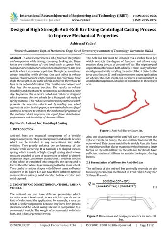
Figure 1. Anti-Roll Bar or Sway Bar.
Anti-roll bars are essential components of a vehicle suspension system. They are inexpensive and simple devices which can be installed in any conventional and older vehicles. They greatly enhance the performance of the vehicle while cornering. It is basically a U shaped torsion spring which is made of high strength spring steel whose ends are attached to pars of suspension or wheel to absorb maximum impact and wheel translations. The linear motion of the wheel is translated into torque by the spring and it forces the other wheel to remain aligned to the main wheel. They can be in various shapes with different turns and bends as shown in the figure 1. It can have three different types of cross-sections namely solid circular, hollow circular and solid tapered.
Also, one disadvantage of the anti-roll bar is that when the vehicle travels on bumps, the anti-roll bar tends to lift the other wheel. This causes instability in vehicle. Also, this force is impulsive and has a large magnitude which induces a large torque on the anti-roll bar. So, the anti-roll bar should have sufficient torsional stiffness to sustain the impact during bumps. 2.1 Formulation of stiffness for Anti-Roll bar The stiffness of the anti-roll bar generally depends on the following parameters mentioned in Fred Puhn’s Sway Bar Stiffness Formula.
2. GEOMETRY AND CONNECTION OF ANTI-ROLL BAR IN A VEHICLE.
(1)
The anti-roll bar can have different geometries which includes several bends and curves which is specific to the kind of vehicle and the application. For example, a race car needs a stiffer suspension because they have low ground clearance and the wheel swing is lesser in comparison to a commercial vehicle. The weight of a commercial vehicle is high, and it has large wheel swing.
© 2020, IRJET
|
Impact Factor value: 7.34
Figure 2. Dimensions and design parameters for anti-roll bar.
|
ISO 9001:2008 Certified Journal
|
Page 1512
International Research Journal of Engineering and Technology (IRJET)
e-ISSN: 2395-0056
Volume: 07 Issue: 01 | Jan 2020
p-ISSN: 2395-0072
Paramet er OD
Dimensions
ID
www.irjet.net
FIAT 500 (Hatchbac 1.45 k)
Honda Accord 1.45 (Sedan)
Chevrolet Trax (SUV) 1.5
Inner Diameter
1.15
1.25
1.15
R
Effective Arm Length
14
12
15
L
Half Length of Bar
13
11
10
S
Length of Arm
17
16
16
Q
Sway Bar Stiffness
407.86
435.57
715.95
Outer Diameter
enhanced to obtain good torsional strength and at the same time material should be free from defects to avoid catastrophic failure of the component
Table 1. Stiffness calculation for anti-roll bars of Hatchback, Sedan and SUV. In this study, 3 samples of anti-roll bars were taken from different 2016 FIAT 500 (Hatchback), 2016 Honda Accord (Sedan) and 2016 Chevrolet Trax (SUV) categories of vehicles. The Fred Puhn’s Sway Bar Stiffness Formula was used to calculate the stiffness (Q value). In case of Hatchback and Sedan, the stiffness value was almost similar but in case of SUV the stiffness value was very high due to the large mass of the vehicle. To meet the requirements of high performance vehicle, the sway bar should be manufactured with higher stiffness to sustain large dynamic loads. To meet this demand, conventional manufacturing methods should be altered to enhance the manufacturing so that the performance of the anti-roll bar is improved.
Table 2. Anti-roll bar dimensions and vehicle specifications.
The sway bar stiffness (Q value) so obtained from Fred Puhn’s Sway Bar Stiffness Formula was later used in the Torsion Rigidity criteria to obtain angle of twist for different materials which has modulus of rigidity similar to the high strength steel [4] [5]. According to Torsion bar equation [6],
(2) According to Rigidity Criteria condition
Therefore
(3)
Table 3. Calculation of Design parameters using Torsion Rigidity Criteria.
These calculation (Table 3) shows that the angle of twist for anti-roll bars of different categories. The angle of twist is low in case of hatchback and in case of sedan it’s slightly high because of the large mass and same is the case with SUV. This is the common angle of twist value for anti-roll bars [7] [8] which either needs to be reduced in case of Sedans and SUV since the large mass of the vehicle exerts a large torque on the vehicle. Also, at this high torque the material experiences large fatigue loads and can result in development of creep or cracks and can lead to failure [9]. To prevent this, the manufacturing process should be
© 2020, IRJET
|
Impact Factor value: 7.34
3. MATERIALS USED TO MANUFACTURE ANTI-ROLL BAR The most commonly used materials used for manufacturing the anti-roll bar are SAE Class 550 (G5160 to G6150) and Class 700 (G1065 to G1090) Steels. Certain manufacturers also use Titanium Alloys like Ti-6Al-4V (Grade 5). Usage of composite materials like Carbon Fiber [10] [11] has also increased in the recent years.
|
ISO 9001:2008 Certified Journal
|
Page 1513
International Research Journal of Engineering and Technology (IRJET)
e-ISSN: 2395-0056
Volume: 07 Issue: 01 | Jan 2020
p-ISSN: 2395-0072
www.irjet.net
Material
Density
Young’s Modulus
Shear Modulus
Shear Strength
Poisson’ s Ratio
SAE Class 550
7.85
190-210
80
390-700
0.27-0.3
highly symmetrical casting. The casting is then allowed to cool and later taken out. The casting orientation can vertical or horizontal depending on the part geometry.
SAE Class 700
7.85
200
80
470
0.27-0.3
Stages of development of Anti Roll Bar
Ti-6-Al-4V
4.43
120
44
550
0.342
Carbon Fiber
2.25
520
5.6
590
0.950
The Anti-roll bar will be developed in the following stages using the proposed manufacturing process. 1. Centrifugal Casting of Hollow Pipe
Table 4. Mechanical Properties of Anti-roll bar materials. 4. CONVENTIONAL MANUFACTURING PROCESS The Anti-roll bars are manufactured by the process of extrusion (which makes the hollow pipes), followed by roll bending (which gives shape to the anti-roll bar), hot pressing (to flatten the ends for easy installation), chipping (to chip extra material), hole punching, tempering (heat treatment to enhance mechanical properties), shot peeing (to induce surface hardening) and finally corrosion coating (to protect the surface from getting corroded).
Figure 4. Hollow Pipe obtained from Centrifugal casting. 2. Bending of the Hollow Pipe
This process involves the use of extrusion which has the following disadvantages on the anti-roll bar in its manufacturing and operation. If the hollow pipe is extruded, there are chances of eccentricity in the pipe which leads to unequal distribution of forces on the hollow pipe cross section and hence leads to failure. There are also chances of ‘die-swelling’ which occurs when the material expands when it comes out of the die. This also leads to uneven expansion of material and creates irregular geometry. Also due to the die-swelling, there are chances of porosity or voids and hence this porous material can lead to failure on application of high torque.
Figure 5. Bending of hollow pipe using Roll Bending Process. 3. Acquiring the shape of the Anti-roll bar
5. PROPOSED MANUFACTURING PROCESS To eliminate the porosity and uneven cross section, the process or centrifugal casting is produced as a replacement to enhance the manufacturing of anti-roll bars. The process is as shown below.
Figure 6. Finishing process to obtain the correct geometry of anti-roll bar. 4. Stamping process to obtain flat surface for attachment.
Figure 3. Flow chart of the proposed manufacturing process for manufacturing anti-roll bar. Centrifugal casting process [12] is performed rotating a permanent mold continuously at 500-3000 RPM when the metal is casted into it. Due to rotation, centrifugal forces evenly pushes away the metal on the walls which results in a
© 2020, IRJET
|
Impact Factor value: 7.34
Figure 7. Stamping process used to obtain a flat surface for easy assembly.
|
ISO 9001:2008 Certified Journal
|
Page 1514
International Research Journal of Engineering and Technology (IRJET)
e-ISSN: 2395-0056
Volume: 07 Issue: 01 | Jan 2020
p-ISSN: 2395-0072
www.irjet.net
5. Punching holes to fix screws.
Figure 8. Punching process used to obtain holes for fixing screws.
Figure 10. Equivalent Stress of Anti-Roll Bar.
6. Heat treatment of the part
Figure 9. Heat treatment of the finished part to enhance mechanical properties Figure 11. Equivalent Elastic Strain of Anti-Roll Bar.
6. TORSION ANALYSIS OF ANTI-ROLL BAR Torsion Analysis of Anti-Roll Bar was done on ANSYS Workbench 17.1. The following conditions have been considered for simulation. Kerb Weight of Honda Accord = 1420 kg Unsprung weight of car is 15% of the kerb weight = 0.15 x 1420 = 213 kgs. Weight acting on one suspension = 213/4 = 53.25 kg M = 53.25
Figure 12.Total Deformation of Anti-Roll Bar.
F= m (g-a)
7. ADVANTAGES OF USING CENTRIFUGAL CASTING TO MANUFACTURE ANTI-ROLL BAR
a = 0.722 m/s2 (acceleration of suspension during translation over a speed bump) F = 53.25 (9.81-0.722) = 483.936 N ~ 484 N FOS = 3 Final Force = 1452 N
Figure 13.Extruded part with Eccentricity and dispersed impurities on the left. Centrifugal casting with concentric hollow casting and accumulated impurities on the circumference.
© 2020, IRJET
|
Impact Factor value: 7.34
|
ISO 9001:2008 Certified Journal
|
Page 1515
International Research Journal of Engineering and Technology (IRJET)
e-ISSN: 2395-0056
Volume: 07 Issue: 01 | Jan 2020
p-ISSN: 2395-0072
www.irjet.net
Centrifuge process also pushes away impurities on the ends of casting. Upon solidification, this can be machined to obtain a pure casting free from impurities. This enhances the torque distribution on the cross section which helps the designers to design a compact, lightweight and effective anti-roll bar.
minimizes porosity and reduces chances of failure. It also reduces the defects and material rework of the casting is greatly reduced since there is no use of risers. Centrifugal casting is also economically feasible and suitable for mass production. Hence this new casting process enhances the manufacturing and functional capabilities of the anti-roll bar and hence it can be substituted in place of extrusion process to obtain better finished product. Further the centrifugal casting can be done at various speeds to obtain different densities of castings.
Centrifugal castings are usually highly dense and symmetric. Due to rotation, high porosity and midwall defects are eliminated and hence the material has homogenous density [13]. This improves the performance of the anti-roll bar in dynamic conditions and high torque applications.
REFERENCES
The cooling takes place from outside surface to inside surface and hence the part is free from any shrinkage cavities, gas pockets or blowholes. This form of cooling also induces fine grain casting which enhances the mechanical properties like yield strength, tensile strength and the material has longer life.
1.
Rajamani R, Piyabongkarn D, Tsourapas V and Lew J, “Parameter and State Estimation in Vehicle Roll Dynamics”, IEEE Transactions on Intelligent Transportation Systems, Vol 2 No 4, 2011.
2.
Cerit M, Nart E, Genel K, “Investigation into Effect of Rubber Bushing on Stress Distribution and Fatigue Behavior of Anti- Roll Bar”, Engineering Failure Analysis, 2010.
3.
Dhakar A. and Ranjan R., “Force Calculation in Upright of FSAE Car”, International Journal of Mechanical Engineering and Technology, Volume 7, Issue 2, March-April 2016, pp. 168–176, IJMET_07_02_018, 2016.
4.
Gosslelin-Brisson S, Bouazara M and Richard M.J., “Design of And Active Anti Roll Bar for Off-Road Vehicles”, Shocks and Vibration, 2009, doi:10.3233/SAV-2009-0459.
5.
Mariappa A, “Design and Optimization of Anti-Roll Bar”, Kaunas University of Technology, 2018.
6.
Joseph A. Untener and Robert L. Mott, in Applied Strength of Materials, 2017, pp. 210-214.
7.
Harshal B, Rushikesh K, Baskar P., “Finite Element Analysis of Anti-Roll Bar to Optimize the Stiffness of the Anti-Roll Bar and the Body Roll”, International Journal of Modern Engineering Research, Volume 4, Issue 5, IJMER-45031123.
8.
Mallapur S and Platz R, “Uncertainty Quantification in The Mathematical Modellingof a Suspension Strut Using Bayesian Interface”, Mechanical Systems and Signal Processing, 2018.
9.
Bayrakceken H, Tasgetiren S, Aslantas K, “Fracture of Automobile Anti-Roll Bar”, Engineering Failure Analysis, 2005.
1) Economic Advantages of Centrifugal casting
It reduces manufacturing costs since material wastage, elimination of parts and machining time is greatly reduced.
It is also suitable for mass production and reduces high inventory costs.
It also provides flexibility to manufacture parts of different sizes and geometries.
Gates and risers are not needed in this process.
Usually lesser temperature of molten metal is required for this casting process and hence it saves a lot of money and energy.
After casting processes are reduced.
CONCLUSION In this paper, the anti-roll bar was chosen for study where its functionality was defined and its role in vehicle stability and control. Fred Puhn’s Sway Bar Stiffness Formula was used to calculate the stiffness of 3 different anti-roll bars from Hatchback, Sedan and SUV segment. The results were formulated, and later Torsion bar equation was used to calculate other parameters like polar moment of inertia and angle of twist. This angle of twist was compared with the existing values and hence a change in manufacturing process was proposed. The conventional manufacturing process which uses extrusion process had demerits and defects which leads to functional instabilities and increase chances of failure in the anti-roll bar. So extrusion process was replaced by centrifugal casting which greatly enhances the mechanical properties,
© 2020, IRJET
|
Impact Factor value: 7.34
10. Michael D., “Design and Development of a Composite
Automotive Anti-Roll Bar”, University of Windsor, 2013
|
ISO 9001:2008 Certified Journal
|
Page 1516
International Research Journal of Engineering and Technology (IRJET)
e-ISSN: 2395-0056
Volume: 07 Issue: 01 | Jan 2020
p-ISSN: 2395-0072
www.irjet.net
11. D.J. Johnson, in Carbon Fibers Filaments and
Composites, edited by J.L. Figueiredo, C.A. Bernardo and K.J. Huttinger, Kluwer Academic, Dordrecht, 1990, pp. 119-146. 12. Sufei W., “Centrifugal Casting”, ASM Handbook Vol 15,
pp 667-673, 2008, doi:10.1361/asmhba0005257. 13. Degarmo E, Black J and Kosher R, in Materials and
Processes in Manufacturing, 2011, pp. 333-335. ACKNOWLEDGMENTS I would like to thank University of Michigan-Dearborn for their support.
© 2020, IRJET
|
Impact Factor value: 7.34
|
ISO 9001:2008 Certified Journal
|
Page 1517