International Research Journal of Engineering and Technology (IRJET)
e-ISSN: 2395-0056
Volume: 07 Issue: 01 | Jan 2020
p-ISSN: 2395-0072
www.irjet.net
Resolve Error with Detection & Correction Techniques in Computer Networks Yashveer Singh1, Anurag Chandna2 1,2Department of Computer Science & Engineering, Roorkee College of Engineering, Roorkee
---------------------------------------------------------------------***----------------------------------------------------------------------
Abstract:- In digital systems, the analog signals will change into digital sequence. This sequence of bits is called as “Data stream”. The objective of this paper that the change in position of single bit also leads to major error in data output. In t his paper we find errors and we use error detection and correction techniques to get the exact or approximate output. Key Words: Keywords: Error Detecting Codes, Error Detection and Correction Techniques. I. INTRODUCTION An error is a situation when the output information does not match the input information. During transmission, digital signals suffer from noise that may introduce errors in binary bits traveling from one system to another. This means that 0 bit can change to 1 or 1 bit can change to 0.. In digital communication system errors are transferred from one communication system to another with data. If these errors are not detected and corrected, the data will be lost. For effective communication, data must be transferred with high accuracy. This can be achieved by first detecting errors and then correcting them. Error detection is the process of detecting errors in the data transmitted in a communication system from the transmitter to the receiver. We use some redundancy codes to detect these errors, connecting them to the data while it is transmitted from the source (transmitter). These codes are called “Error detecting codes ".
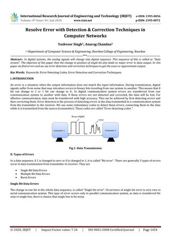
Fig 1: Data Transmission II. Types of Errors In a data sequence, if 1 is changed to zero or 0 is changed to 1, it is called “Bit error”. There are generally 3 types of errors occur in data transmission from transmitter to receiver. They are
Single Bit Data Errors Multiple Bit Data Errors Burst Errors
Single Bit Data Errors The change in one bit in the whole data sequence, is called “Single bit error”. Occurrence of single bit error is very rare in serial communication system. This type of error occurs only in parallel communication system, as data is transferred bit wise in single line, there is chance that single line to be noisy.
© 2020, IRJET
|
Impact Factor value: 7.34
|
ISO 9001:2008 Certified Journal
|
Page 1454
International Research Journal of Engineering and Technology (IRJET)
e-ISSN: 2395-0056
Volume: 07 Issue: 01 | Jan 2020
p-ISSN: 2395-0072
www.irjet.net
Multiple Bit Data Errors If there is change in two or more bits of data sequence of transmitter to receiver, it is called “Multiple bit error”. This type of error occurs in both serial type and parallel type data communication networks.
Burst Errors The change of set of bits in data sequence is called “Burst error”. The burst error is calculated in from the first bit change to last bit change.
Here we identify the error form fourth bit to 6th bit. The numbers between 4th and 6th bits are also considered as error. These set of bits are called “Burst error”. These burst bits changes from transmitter to receiver, which may cause a major error in data sequence. This type of errors occurs in serial communication and they are difficult to solve. III. Error Detecting Codes Along with error-detecting code, we can also pass some data to figure out the original message from the corrupt message that we received. This type of code is called an error-correcting code. Error-correcting codes also deploy the same strategy as error-detecting codes but additionally, such codes also detect the exact location of the corrupt bit. In error-correcting codes, parity check has a simple way to detect errors along with a sophisticated mechanism to determine the corrupt bit location. Once the corrupt bit is located, its value is reverted (from 0 to 1 or 1 to 0) to get the original message. In this paper to detect and correct the errors, additional bits are added to the data bits at the time of transmission. The additional bits are called parity bits. They allow detection or correction of the errors.The data bits along with the parity bits form a code word. IV. Parity Checking Parity bit means nothing but an additional bit added to the data at the transmitter before transmitting the data. Before adding the parity bit, number of 1’s or zeros is calculated in the data. Based on this calculation of data an extra bit is added to the actual information / data. The addition of parity bit to the data will result in the change of data string size. This means if we have an 8 bit data, then after adding a parity bit to the data binary string it will become a 9 bit binary data string. Parity check is also called as “Vertical Redundancy Check (VRC)”.
© 2020, IRJET
|
Impact Factor value: 7.34
|
ISO 9001:2008 Certified Journal
|
Page 1455
International Research Journal of Engineering and Technology (IRJET)
e-ISSN: 2395-0056
Volume: 07 Issue: 01 | Jan 2020
p-ISSN: 2395-0072
www.irjet.net
There is two types of parity bits in error detection, they are
Even parity Odd parity
Even Parity
If the data has even number of 1’s, the parity bit is 0. Ex: data is 10000001 -> parity bit 0 Odd number of 1’s, the parity bit is 1. Ex: data is 10010001 -> parity bit 1
Odd Parity
If the data has odd number of 1’s, the parity bit is 0. Ex: data is 10011101 -> parity bit 0 Even number of 1’s, the parity bit is 1. Ex: data is 10010101 -> parity bit 1
NOTE: The counting of data bits will include the parity bit also and the parity bits received at receiver are not equal then an error is detected. The circuit which checks the parity at receiver is called “Parity checker”.
Fig 2 : Messages with even parity and odd parity. Error Detecting Techniques This approach implemented either at Data link layer or Transport Layer of OSI Model. Whenever a message is transmitted, it may get scrambled by noise or data may get corrupted. To avoid this, we use errordetecting codes which are additional data added to a given digital message to help us detect if any error has occurred during transmission of the message. Basic approach used for error detection is the use of redundancy bits, where additional bits are added to facilitate detection of errors. 1. 2. 3. 4. 5.
Some popular techniques for error detection are:Simple Parity check Two-dimensional Parity check Checksum Cyclic redundancy check
1. Simple Parity check Blocks of data from the source are subjected to a check bit or parity bit generator form, where a parity of :
1 is added to the block if it contains odd number of 1’s, and 0 is added if it contains even number of 1’s
This scheme makes the total number of 1’s even, that is why it is called even parity checking.
© 2020, IRJET
|
Impact Factor value: 7.34
|
ISO 9001:2008 Certified Journal
|
Page 1456
International Research Journal of Engineering and Technology (IRJET)
e-ISSN: 2395-0056
Volume: 07 Issue: 01 | Jan 2020
p-ISSN: 2395-0072
www.irjet.net
2. Two-dimensional Parity check Parity check bits are calculated for each row, which is equivalent to a simple parity check bit. Parity check bits are also calculated for all columns, then both are sent along with the data. At the receiving end these are compared with the parity bits calculated on the received data. Original data is
10011001
11100010
100100
10000100
Row Parities
Column Parities 100110010
10011001
0
11100010
0
10011001
0
10000100
0
11011011
0
111000100
1001000
100001000
110110110
Data to be sent 3. Checksum In checksum error detection scheme, the data is divided into k segments each of m bits.In the sender’s end the segments are added using 1’s complement arithmetic to get the sum. The sum is complemented to get the checksum. The checksum segment is sent along with the data segments. At the receiver’s end, all received segments are added using 1’s complement arithmetic to get the sum. The sum is complemented. If the result is zero, the received data is accepted; otherwise discarded.
© 2020, IRJET
|
Impact Factor value: 7.34
|
ISO 9001:2008 Certified Journal
|
Page 1457
International Research Journal of Engineering and Technology (IRJET)
e-ISSN: 2395-0056
Volume: 07 Issue: 01 | Jan 2020
p-ISSN: 2395-0072
www.irjet.net
4. Cyclic redundancy check (CRC) Unlike checksum scheme, which is based on addition, CRC is based on binary division. In CRC, a sequence of redundant bits, called cyclic redundancy check bits, are appended to the end of data unit so that the resulting data unit becomes exactly divisible by a second, predetermined binary number. At the destination, the incoming data unit is divided by the same number. If at this step there is no remainder, the data unit is assumed to be correct and is therefore accepted. A remainder indicates that the data unit has been damaged in transit and therefore must be rejected.
© 2020, IRJET
|
Impact Factor value: 7.34
|
ISO 9001:2008 Certified Journal
|
Page 1458
International Research Journal of Engineering and Technology (IRJET)
e-ISSN: 2395-0056
Volume: 07 Issue: 01 | Jan 2020
p-ISSN: 2395-0072
www.irjet.net
Example:
Conclusions: This paper presents errors occurs along with error-detecting code, we can also pass some data to figure out the original message from the corrupt message that we received. This type of code is called an error-correcting code. Error-correcting codes also deploy the same strategy as error-detecting codes but additionally, such codes also detect the exact location of the corrupt bit. In error-correcting codes, parity check has a simple way to detect errors along with a sophisticated mechanism to determine the corrupt bit location. Once the corrupt bit is located, its value is reverted (from 0 to 1 or 1 to 0) to get the original message. References:
Thompson, Thomas M. (1983), From Error-Correcting Codes through Sphere Packings to Simple Groups, The Carus Mathematical Monographs (#21), The Mathematical Association of America, p. vii, ISBN 0-88385-023-0 Shannon, C.E. (1948), "A Mathematical Theory of Communication", Bell System Technical Journal, p. 418, 27 Golay, Marcel J. E. (1949), "Notes on Digital Coding", Proc.I.R.E. (I.E.E.E.), p. 657, 37 Gupta, Vikas; Verma, Chanderkant (November 2012). "Error Detection and Correction: An Introduction" (PDF). International Journal of Advanced Research in Computer Science and Software Engineering. 2 (11). Retrieved August 21, 2019. J. McAuley, Reliable Broadband Communication Using a Burst Erasure Correcting Code, ACM SIGCOMM, 1990. Frank van Gerwen. "Numbers (and other mysterious) stations". Retrieved 12 March 2012. Gary Cutlack (25 August 2010). "Mysterious Russian 'Numbers Station' Changes Broadcast After 20 Years". Gizmodo. Retrieved 12 March 2012. Ben-Gal I.; Herer Y.; Raz T. (2003). "Self-correcting inspection procedure under inspection errors" (PDF). IIE Transactions on Quality and Reliability, 34(6), pp. 529-540. K. Andrews et al., The Development of Turbo and LDPC Codes for Deep-Space Applications, Proceedings of the IEEE, Vol. 95, No. 11, Nov. 2007. Huffman, William Cary; Pless, Vera S. (2003). Fundamentals of Error-Correcting Codes. Cambridge University Press. ISBN 978-0-521-78280-7. Scott A. Moulton "A Survey of Techniques for Improving Error-Resilience of DRAM", Journal of systems architecture, 2018 "Using StrongArm SA-1110 in the On-Board Computer of Nanosatellite". Tsinghua Space Center, Tsinghua University, Beijing. Retrieved 2009-02-16.[permanent dead link] Jeff Layton. "Error Detection and Correction". Linux Magazine. Retrieved 2014-08-12. "Documentation/edac.txt". Linux kernel documentation. kernel.org. 2014-06-16. Archived from the original on 2009-09-05. Retrieved 2014-08-12. Behrouz A. Forouzan, “Data Communication and Networking”, 3 rd Edition, Tata McGraw Hill, 2004. William Stallings, “Data and Computer Communications”, 8th Edition, Pearson Education, 2007. Leon-Garcia, Indra Widjaja, “Communication Networks”, 2nd Edition, Tata McGraw-Hill, 2004.
© 2020, IRJET
|
Impact Factor value: 7.34
|
ISO 9001:2008 Certified Journal
|
Page 1459