International Research Journal of Engineering and Technology (IRJET) e-ISSN: 2395-0056 Volume: 11 Issue: 06 | Jun 2024
www.irjet.net
p-ISSN: 2395-0072
SIMULATION AND MODELLING OF NONISOLATED BIDIRECTIONAL ZERO-VOLTAGE-SWITCHING DC–DC CONVERTER Mrs Anusree Shibindas, Mrs Usha Rebecca2 1 Assistant professor, Rajiv Gandhi Institute of Technology, Bengaluru, Karnataka, India. 2Assistant professor, Rajiv Gandhi Institute of Technology, Bengaluru, Karnataka, India
---------------------------------------------------------------------***---------------------------------------------------------------------
Abstract
-
nonisolated bidirectional converter is proposed in this paper.
A new nonisolated zero voltage switching(ZVS)bidirectional dc-dc converter is proposed in this paper. Bidirectional converters have been widely used in various industrial applications such as uninterruptible power supplies, fuel cell vehicle, and satellite applications. A bidirectional converter controls the power flow between the dc bus and the low voltage sources such as back-up batteries, fuel cell, and super capacitors. The proposed converter utilizes a very simple auxiliary circuit that consist of an additional winding to the main inductor and an auxiliary inductor to provide ZVS of the power switches and a ripple free inductor current. A comparative study between the conventional nonisolated bidirectional dc–dc converter and the proposed nonisolated bidirectional ZVS dc–dc converter is analyzed and simulation is done in MATLAB software and the practical implementation of the proposed converter is done.
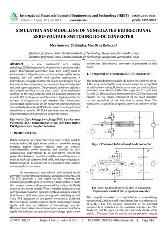
1.1 Proposed Bi-directional DC-DC converter: The proposed bidirectional dc–dc converter is shown in Fig1. It is very similar to the conventional converter except that an additional winding Ns to the main inductor and auxiliary inductor Ls are added and the filter capacitor Cf is split into Cf1 and Cf2. This auxiliary circuit provides ZVS function and cancels out the ripple component of the main inductor current regardless of the direction of power flow. The equivalent circuit of the proposed converter is shown in Fig2.
Key Words: Zero Voltage Switching (ZVS), Zero Current Switching (ZCS), Bidirectional DC-DC convertor (BDC), PWM generators, Coupled inductor.
1. INTRODUCTION Bidirectional dc–dc converters have been widely used in various industrial applications such as renewable energy systems, hybrid electric vehicle, fuel cell vehicle, uninterruptible power supplies, and satellite. In such applications, bidirectional dc–dc converters control the power flow between the dc bus and the low-voltage sources such as back-up batteries, fuel cells, and super capacitors. Bidirectional dc–dc converters are classified into isolated and nonisolated versions.
Fig – 1: Proposed bidirectional dc-dc converter
In conventional nonisolated bidirectional dc–dc converter, it operates in continuous conduction mode (CCM). The CCM provides a low ripple current. However, the switching loss of the power switches is large and there exists the reverse recovery phenomenon of the antiparallel body diode of the power switch. With a smaller inductance, the conventional converter operates with an inductor current that flows in both directions during each switching period. Then ZVS operation of the power switches is achieved. However, large inductor current ripple causes large voltage ripple and shortens lifetime of low-voltage sources. However, to avoid reverse recovery phenomenon, to achieve ripple free inductor current, to reduce voltage ripple a new
© 2024, IRJET
|
Impact Factor value: 8.226
Fig -Error! No text of specified style in document.: Equivalent circuit of the proposed converter The coupled inductor Lc is modeled as a magnetizing inductance Lm and an ideal transformer that has a turn ratio of Np:Ns = 1:n. The leakage inductance of the coupled inductor Lc is included in the auxiliary inductor Ls. The diodes D1 and D2 represent the intrinsic body diodes of S1 and S2 . The capacitors C1 and C2 are the parasitic output
|
ISO 9001:2008 Certified Journal
|
Page 544