International Research Journal of Engineering and Technology (IRJET) e-ISSN: 2395-0056 Volume: 11 Issue: 06 | Jun 2024
www.irjet.net
p-ISSN: 2395-0072
BLDC MOTOR CONTROL BY PID CONTROLLER IN MATLAB FOR ELECTRICAL VEHICAL APPLICATION Swati Soni1, Miss Preeti Sahu2, Dr. Durga Sharma3 1Department of Electrical Engineering, Dr. CVRU Kota Bilaspur Chhattisgarh, India
2Asst. Professor, Dept. of Electrical Engineering, Dr. CVRU Kota Bilaspur Chhattisgarh, India 3 Asst. Professor, Dept. of Electrical Engineering, Dr. CVRU Kota Bilaspur Chhattisgarh, India ---------------------------------------------------------------------***---------------------------------------------------------------------
Abstract - Recent advancements in magnetic materials
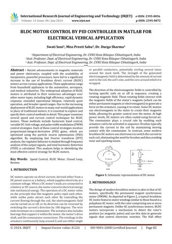
or parallel conductors, potentially circling several times around the stack teeth. The strength of the generated electromagnetic field is determined by the amount of current sent to the coil, the coil's size, and the core around which it is wrapped.
and power electronics, coupled with the availability of inexpensive, powerful processors, have led to a significant increase in the use of brushless direct current (BLDC) motors across various applications. These applications range from household appliances to the automotive, aerospace, and medical industries. The widespread adoption of BLDC motors is attributed to their numerous advantages over other motor types, including high efficiency, rapid dynamic response, extended operational lifespan, relatively quiet operation, and broader speed ranges. Due to the increasing deployment of BLDC motors in many real-world applications in place of traditional motors, it is essential to explore and specify their control methods in detail. This paper examines several speed and current control techniques for BLDC motors. These methods include hysteresis band control, variable DC-link voltage, and pulse width modulation (PWM) control strategies. Each of these control strategies involves proportional-integral-derivative (PID) gains, which are optimized using the particle swarm optimization (PSO) algorithm. By employing fast Fourier transform (FFT) analysis, the regulator behavior is studied through frequency analysis of the output signals, and total harmonic distortion (THD) is calculated. This analysis helps in identifying the most effective control strategy for BLDC motors.
The direction of the electromagnetic fields is controlled by turning specific coils on or off in sequence, creating a rotating magnetic field. These rotating fields interact with the magnetic fields of the stator's magnets (which can be either permanent magnets or electromagnets) to generate a force on the armature, causing it to rotate. Some DC motors use electromagnets in the stator to create their magnetic fields, allowing for greater control over the motor. At high power levels, DC motors are often cooled using forced air. The commutator plays a crucial role by enabling each armature coil to be activated in sequence. Brushes typically provide the current to the coil by maintaining moving contact with the commutator. In contrast, some modern brushless DC motors use electronics to switch the current to each coil, eliminating the need for brushes and thus avoiding wear and sparking issues.
Key Words: Speed Control, BLDC Motor, Closed Loop, Review.
1. INTRODUCTION Figure 1: Schematic representation of DC motor
DC motors operate on direct current, derived either from a DC power source or a battery, which supplies electricity at a constant voltage. When a DC motor's leads are connected to a battery or DC source, the motor converts electrical energy into mechanical energy. The operation of a DC motor relies on the principle that like magnetic poles repel each other, while unlike poles attract each other By controlling the current flowing through the coil, the electromagnetic field can be turned on or off, or its direction can be reversed by switching the current's direction by 180 degrees. The wire ends terminate on a commutator. The armature also includes bearings that support it within the motor, the motor's drive shaft, and the commutator connections. The windings in the armature continuously loop around it and use either single
© 2024, IRJET
|
Impact Factor value: 8.226
2. METHODOLOGY The design of modern brushless motors is akin to that of AC motors, specifically the permanent magnet synchronous motor (PMSM). As depicted in Figure 2, a typical brushless DC motor features stator windings similar to those found in a polyphase AC motor, with the rotor comprising one or more permanent magnets. Unlike AC synchronous motors, BLDC motors incorporate a mechanism to detect the rotor's position (or magnetic poles) and use this data to generate signals that control electronic switches. The Hall effect
|
ISO 9001:2008 Certified Journal
|
Page 82