International Research Journal of Engineering and Technology (IRJET)
e-ISSN: 2395-0056
Volume: 11 Issue: 04 | Apr 2024
p-ISSN: 2395-0072
www.irjet.net
SIMULATION OF SINGLE PHASE CYCLOCONVETER FOR INDUSTRIAL APPLICATION Asst.Professor M D L Saranya1, K Girivardan2, A Dinesh3, Ch Bangaru Talli4 1Head of Department, Dept. of EEE, Visakha Institute of Engineering & Technology, A.P, India 2Student, Dept. of EEE, Visakha Institute of Engineering & Technology, A.P, India 3Student, Dept. of EEE, Visakha Institute of Engineering & Technology, A.P, India 4Student, Dept. of EEE, Visakha Insti tute of Engineering & Technology, A.P, India
---------------------------------------------------------------------***--------------------------------------------------------------------1.1: TYPES OF CYCLOCONVERTERS
ABSTRACT – The variable frequency power electronic
system design is having a great importance in various types of industrial applications. To fulfill those requirements of variable frequency, cycloconverters are widely used. Cycloconverter is a power electronics device which converts input power at one frequency into output power at different frequency.
There are two main types of cycloconverters: 1)Blockingmodetype 2)Circulatingmodetype When the load current is positive, the positive converter supplies the required voltage, and the negative converter is blocked. Suppose if the load current is negative, then the negative converter supplies the voltage and the positive converter is blocked. This operation is called blocking mode operation.
The firing angles are carefully timed to regulate the output frequency. Thyristors are used as the switching devices in the cycloconverter. Thyristors are triggered to control the output waveform. The output voltage waveform, frequency, and magnitude can be observed as the model changes the firing angles and load conditions.
By chance, if both converters are enabled, then the supply will be short-circuited. To avoid this, an intergroup reactor (IGR) must be connected between the converters. If both the converters are enabled, then a circulating current is produced. This is unidirectional because the thyristors allow the current to flow in only one direction. The cyclo converters using this approach are called circulating current converters.
Key Words: Converter, Single phase cycloconverter, Simulation, power electronic circuit, variable frequency converter, waveforms, Parameters for R load
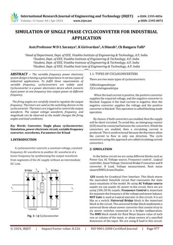
1.INTRODUCTION A cycloconverter converts a constant voltage, constant frequency AC waveform to another AC waveform of a lower frequency by synthesizing the output waveform from segments of the AC supply without an intermediate DC Link. Bridge 1
2: SIMULATION In the below circuit we are using different blocks such as Power Gui, AC Voltage source, Frequency control , Logical controller, Input Voltage, Universal Bridge P converter and N converter, R Load, Voltage measurement, Root mean square(RMS),Scope,Display.
Bridge 2
GUI stands for Graphical User Interface. This block stores the equivalent Simulink circuit that represents the state space equations of the model. By using AC Voltage source supply we can supply AC power to the circuit. Here we are using 230v,50 Hz supply. Frequency Control is important for maintain the frequency of the voltage and power balance. NOT Gate is used as Logical operator in this circuit. It is act like as a switch. Universal Bridge block is the important block in the circuit. The universal bridge block implements a universal three-phase power converter that consist of up to six power switches connected in a bridge configuration. The RMS block stands for Root Mean Square value of each row or column of the input, or along vectors of a specified dimension of the input. We are using R load in this circuit.
Fig. 1: 1ϕ Cycloconverter
© 2024, IRJET
|
Impact Factor value: 8.226
|
ISO 9001:2008 Certified Journal
|
Page 977