International Research Journal of Engineering and Technology (IRJET)
e-ISSN: 2395-0056
Volume: 11 Issue: 02 | Feb 2024
p-ISSN: 2395-0072
www.irjet.net
Maximum and Minimum Variation of Wheel Geometry through Worst Case & RSS Method Mohan Patwari1, Ravindra Kachare2, Sujeet Kumar3 1Sr. Design Engineer, Tata Technologies, ERC, Chassis, Tata Motors, Pune Maharashtra, India 2Team Lead, Tata Technologies, ERC, Chassis, Tata Motors, Pune Maharashtra, India 3Sr. Manager, ERC, Chassis, Tata Motors, Pune Maharashtra, India
---------------------------------------------------------------------***---------------------------------------------------------------------
Abstract – Camber angle is one of the main parameters of suspension system which affects, tire wear and handling of the vehicle. Camber angle is formed when vertical axis or top corner of tire is inclined outward or inward when seen from front or rear. Camber angle is said to be positive if top corner of the tire is outward and bottom corner of tire is inward. Camber is negative if top corner of tire is inward and bottom corner of tire is outward. Positive and negative camber set depending upon the suspension system geometry requirement. Static camber value varies if camber contributor parts are not in specified tolerance limit. To check maximum or minimum camber variation as per the tolerance given in part like control arm, chassis, wheel end etc., a tolerance stackup analysis is performed which helps to get maximum and minimum camber value. Vehicle behavior as per camber variation can be forecasted and it also shows the tolerance which to be controlled to minimize camber thrust, tire wear and poor ride handling [5]. Key Words: Tolerance stackup analysis for camber variation.
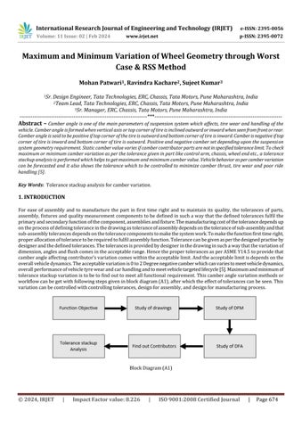
1. INTRODUCTION For ease of assembly and to manufacture the part in first time right and to maintain its quality, the tolerances of parts, assembly, fixtures and quality measurement components to be defined in such a way that the defined tolerances fulfil the primary and secondary function of the component, assemblies and fixture. The manufacturing cost of the tolerance depends up on the process of defining tolerance in the drawing as tolerance of assembly depends on the tolerance of sub-assembly and that sub-assembly tolerances depends on the tolerance components to make the system work. To make the function first time right, proper allocation of tolerance to be required to fulfil assembly function. Tolerance can be given as per the designed practise by designer and the defined tolerances. The tolerances is provided by designer in the drawing in such a way that the variation of dimension, angles and flush comes in the acceptable range. Hence the proper tolerances as per ASME Y14.5 to provide that camber angle affecting contributor’s variation comes within the acceptable limit. And the acceptable limit is depends on the overall vehicle dynamics. The acceptable variation is 0 to 2 Degree negative camber which can varies to meet vehicle dynamics, overall performance of vehicle tyre wear and car handling and to meet vehicle targeted lifecycle [5]. Maximum and minimum of tolerance stackup variation is to be to find out to meet all functional requirement. This camber angle variation methods or workflow can be get with following steps given in block diagram (A1), after which the effect of tolerances can be seen. This variation can be controlled with controlling tolerances, design for assembly, and design for manufacturing process.
Block Diagram (A1)
© 2024, IRJET
|
Impact Factor value: 8.226
|
ISO 9001:2008 Certified Journal
|
Page 674