PERFORMANCE ANALYSIS OF PLANAR BANDPASS FILTER WITH DIFFERENT ORDERS
Hrishika1, Priyanka Pradhan21 M-Tech Student, Department of Electronics & Telecommunication Engineering, Lakshmi Narain College of Technology, Indore M.P. INDIA
2 Assistant Professor, Department of Electronics & Telecommunication Engineering, Lakshmi Narain College of Technology, Indore M.P. INDIA
Abstract - Filter is a very essential component in modern communication system as it is used to separate out desired signal from entire range of frequency so as to process the signal to acquire the required output. In this work bandpass filters are designed on microstrip patterns through coupled line topology by using the design equations available in literatures at 4.9 GHz frequency on FR4 substrate with dielectricconstant4.5andsameisimplementedincommercial simulation software. Subsequently, the coupled line filter topology is attemptedwith different orders namely3rd order, 4th order,andfifthorderandtheeffectvariousordersinfilter performanceisanalysedintermsofinsertionloss,returnloss, bandwidth, roll-off etc. Further, a comparative analysis is carried out among all the designs and feasibility of practical implementation is discussed in this article.
Key Words: Bandwidth,Filter,passband,microstrip,stop band,roll-off,etc.

1.INTRODUCTION
ModerncommunicationsystemisbeingmigratedfromVHF bandtoUHFandSHFbandshenceallthesystemsneedtobe realisedatmentionedfrequencybands.Incommunication systemfilterisveryimportantaspectasitallowthedesired frequency signal to pass and eliminate the unwanted frequencysignals[1].Theperformanceoffilteralsogetting refineddaybydayandinsertionloss,returnloss,bandwidth, rolloffetc.havebecomekeyperformanceindicatorsforany filter. Now a day’s most of the filters are operated at microwave frequency band and on that frequency band, designingafilterusinglumpedcomponentsispracticallynot possiblehencethedesignapproachisshiftedtowardsother alternativetechnologiesnamelywaveguidebasedfilter[2], microstrip based filter [4], meta-material based filter [3], LTCC filters [8], SAW filter [7], SIW based filter [5] etc. Amongtheavailabletechnologies,microstripbasedfilters are best choice for this study and for commercial applicationstoo,asithasabilitytoworkathighfrequency, smallsize,lightweight,lowcostandfeasibilitytointegrate withothercomponents.
A lot of research is carried out on microstrip based filter designtoimprovetheperformanceintermsofinsertionloss

andreturnlossasdetailedin[4],reducethesizeasdetailed in[5],costreductionasdetailedin[6],variablefrequencyas detailedin[9],variablebandwidthasdetailedin[9].Having analyzedvariousworksofliterature,itisessentialtoanalyse theeffectoforderwhilefilterdesign.
Inthisresearchwork,amicrostrip-basedcoupledlinefilter is designed on FR-4 substrate using the design equations availableintheliterature[10].Subsequently,similartypeof filtersaredesignedwithdifferentordersnamelythirdorder, forth order and fifth order. All the mentioned filters are simulated in Keysight ADS software and comparative analysisiscarriedoutamongtheirperformances.Intheend the feasibility for practical implementation of the same is detailedinthisarticle.
2. DESIGN PRINCIPLE
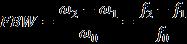
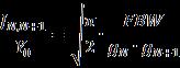
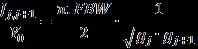
Inordertodesignabandpassfilter,firstlyalowpassfilter prototypeisdesignedandsubsequentlysameisextrapolated to band pass filter. In the process of designing microstrip basedcoupledlinefiltersfollowingequationsareemployed-
whereg0,g1,...,gNaretheelementvaluesofaladder-typelow passprototypewithanormalizedcut-offfrequencyΩc =1. The fractional bandwidth of a band pass filter, defined as FBW,isequalto:
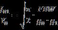
Where, B isthebandwidth,and istheangular resonantfrequency.

Whentheelectricallengthofeachcoupledlineisequaltohalf ofthewavelength,even-modelineimpedanceandodd-mode lineimpedanceareobtained(inOhm).
(5)
(6)
Thephysicalarrangementofcoupledlinefilterisshownin Fig.1.
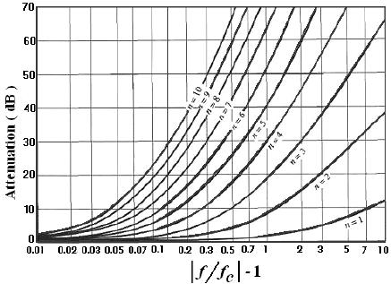
Tobegindesigningafilter,thefirststepistodetermineits order.Thefractionalbandwidthandnormalizedfrequency canbecalculatedusingtheformulaeprovidedinequation (4)Theorderoffiltercanbedeterminedbyexaminingthe attenuationvs.normalizedfrequencygraphfor0.5dBripple, asdepictedinthegraphgivenbelow.
Thecalculatedlinelengthandwidthandspacingareusedin simulationsoftwareforfurtherprocessofdesign.
3. DESIGN METHODOLOGY
The following flow chart explains the entire design methodologyofmicrostripcoupledlinebandpassfilter-
Theelementvaluesforthirdfourthandfifthorderfilter aredeterminedfromTable1.
Flow chart -1:Filterdesignactivity
Alow-passfilterprototypewithButterworthresponsecan be designed using normalized values g1, g2, g3…gN from Table-1. The filter can be designed with three poles, four poles,orfivepoles.Fora3rd orderfilter,theelementvalues areg1 =g3 =1.5963andg2 =1.0967, whilefora 4th order filter,theelementvaluesareg1 =1.6703,g2 =1.1926,g3 = 2.3661,g4=0.8419,andg5=1.9841.Similarly,fora5thorder filter, the element values are g1 = g5 = 1.7058, g2 = g4= 1.2296,g3 =2.5408,andg6 =1.Thecalculatedvaluescanbe usedasprototypevaluesforthefilterdesign.
LC elements were then derived from the normalized element values for the desired mid-band frequency and source impedance of 50 ohms. To create a microstrip bandpassfilterthatapproximatesthelumpedelementfilter, Prototypevaluesforalowpassfilterarecalculatedbasedon thedesignspecificationsprovidedinbelow.
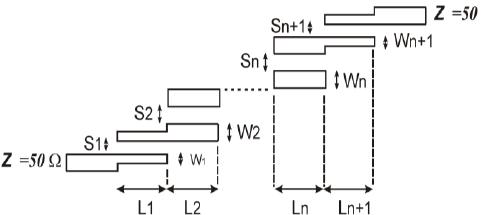
Table -2:Specificationoffilterdesign
FilterType
Butterworth
Numberoforders 3rd ,4th,and5th
Upperfrequency 4.8GHz
Lowerfrequency 5.0GHz
Centrefrequency 4.9GHz(Cband)
Fractional Bandwidth, Δf


0.05or5%
then most important step is an appropriate microstrip realization waschosenand fabricatedona substrate with dielectricconstantεr=4.5andthicknessh=0.2to3.2mm The J-inverter can convert a low pass filter to a bandpass filterbyutilizingtheequationspresentedaboveequation(1) (2)(3).TheequationsconsistofFBW,whichrepresentsthe fractionalbandwidthofthebandpassfilter,aswellasJjand j+1, which denote the characteristic admittances of the Jinverters.Thecharacteristicadmittanceoftheterminating linesisrepresentedbyY0.
Tocreatethe J-inverters,thecharacteristic impedances of theeven-andoddmodesofthecoupledlinesaredetermined usingtheprovidedequations.
Thedesiredfrequencyresponseisachievedbyadjustingthe parameter values, which have been summarized in Table below. The tuning process involves finding the optimal values for the filter parameters to meet the design specifications.
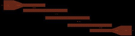
Although the schematic simulation of the filter provides importantinsightsaboutitsperformance,itisnotenoughto confirmitspracticalfeasibility.Therefore,itisessentialto carryoutalayoutsimulationtoensurethedesign'svalidity. To achieve this, ADS generates a layout file from the schematicdesign,whichcanbesimulatedwiththespecified substratecharacteristics.Theresultingoptimizedmicrostrip filterlayoutispresentedbelow
Todeterminethewidth,spacing,andlengthofeachstage, theLineCalctoolinAdvancedDesignSystem(ADS),Agilent Technologies software, is employed. This calculation is carriedoutusingtheevenandoddcharacteristicimpedance values.ThecharacteristicimpedanceZ0isusuallyassumed tobe50Ohms.
Following the determination of the width, spacing, and length of each stage, the next step is optimization. It is criticaltoestablishallparametersandobjectivesproperly during this stage. The optimization and tuning process is then performed to achieve the best possible results and performance.Ultimately,thedimensionsofthewidth,gap, andlengtharefinalizedbasedonthisoptimizationprocess. Finally,thecoupledlinefilterisdesignedinthesimulation software environment, Advanced Design System (ADS), where the filter parameters are input and the software generatesthephysicaldimensionsofthefilterlayoutalong withasimulationofthefilterresponse.
Theschematicdiagramofthethird-orderparallel-coupled bandpass filter shown above depicts the arrangement of resonators connected in parallel. Similarly, for the fourthorderandfifth-orderfilters,theschematicdiagramswould show the arrangement of four and five resonators respectively. In each case, the resonators are carefully designedandinterconnectedtoachievethedesiredfiltering characteristics.Thespecificconfigurationofinductorsand capacitors is employed to construct the resonators. The inputandoutputportsareconnectedtothecentralnodeof the resonators. By this arrangement, the filter is able to selectively pass a narrow band of frequencies centered around the desired center frequency. The inclusion of additional resonators in the higher-order filters enhances thefilter'sperformanceandfrequencyresponseshaping.
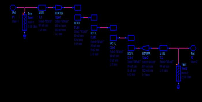
The layout of the third-order parallel-coupled bandpass filter, as well as the fourth-order and fifth-order filters, is determined by the arrangement of resonators and their interconnections.Inthelayout,thedimensionsandpositions of the resonators are carefully specified to achieve the desired filter characteristics. The additional resonators in higher-order filters contribute to improved frequency responseandenhancedfilteringperformance.
4. SIMULATION RESULTS
The calculated parameters namely width, length, and line spacingforeachcoupledlineareenteredinsimulationtool thedesiredfilterisvisualised.Simulationgivesinsertionloss andreturnlossplotsof3rd ,4th and5th orderarementioned below
A bandwidth of 0.239 GHz is observed in the 3rd order bandpass filter, with upper and lower frequencies. At the centerfrequencyof4.900GHz,aninsertionlossof0.946dB and a return loss of 27.53 dB are exhibited. Similarly, a bandwidth of 0.257 GHz is observed in the 4th order bandpass filter, with upper and lower frequencies. At the centerfrequencyof4.900GHz,aninsertionlossof1.015dB andareturnlossof23.215dBareexhibited.Inthecaseof the5thorderbandpassfilter,abandwidthof0.261GHzis observed, with upper and lowerfrequenciesof 5.010GHz and 4.749 GHz. At the center frequency of 4.900 GHz, an insertionlossof1.309dBandareturnlossof27.986dBare exhibited.Theparametervariationsintheplotdemonstrate how the insertion loss and return loss change with an increase in the order of the filter, and they reveal the behaviorofthebandpassfilteratdifferentfrequencies.
4. COMPARATIVE ANALYSIS
Therearethreecoupledlinefiltersarechosenforcarrying outcomparativeanalysis
Fig -8: Comparativeanalysisforfiltersofdifferentorders.
Table -3: Comparisonanalysisforfiltersofdifferentorders
Acomparativeanalysisrevealsvariationsintheparameters oftheplotteddatafordifferentordersofbandpassfilters. The3rdorderfilterhasabandwidthof4.88%,whilethe4th orderand5thorderfiltershavebandwidthsof5.24%and 5.34%GHzrespectively.Theinsertionlossandreturnloss vary among the different orders, with the 3rd order filter
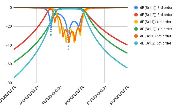

generallyexhibitinglowerlossescomparedtothe4thand 5th order filters. Additionally, the upper and lower frequenciesshiftslightlybetweenthedifferentorders,while thecenterfrequencyremainsconstantat4.900GHzforall threeorders.These parametervariations provideinsights intotheperformancedifferencesandtrade-offsassociated withhigher-orderbandpassfilters.
5. IMPACT ANALYSIS
Comparativeanalysisfordifferentordersgivesabasicidea forchoosingafilterforcommercialapplications.Theimpact ofvarioustopologiesisdetailedbelow-
a) Impact on insertion loss:When comparing the insertionlosses,itisobservedthatastheorderof the filter is increased from the third to the fifth order, the insertion loss is also increased. This observationsuggeststhathigher-orderfiltersmay introduceahigherdegreeofsignalattenuation.It canbeinferredthatwiththeincreaseinthefilter order,thereisanassociatedincreaseintheamount of signal power that is lost. This increase in insertionlosshasimplicationsfortheperformance of the filters, as it may lead to a reduction in the overall signal quality and effectiveness of the filteringprocess.
b) Impact on return loss: Uponanalyzingthereturnloss,itbecomesevident thathigherreturnlossvaluesareexhibitedbythe thirdandfifth-orderfilterswhencomparedtothe fourth-order filter. It is observed that a higher returnlosssignifiesimprovedimpedancematching anddecreasedsignalreflection.Asa resultofthis analysis,itisexpectedthatthethirdandfifth-order filterswilldeliversuperiorperformanceintermsof reducing signal reflections and maintaining impedancematchingincomparisontothefourthorder filter. This implies that the higher-order filters present enhanced signal transmission characteristics and overall performance enhancements.
c) Impact on bandwidth: The bandwidth analysis revealsthatthewidestbandwidthof0.261GHzis observedinthefifth-orderbandpassfilter,followed bythefourth-orderfilterwithabandwidthof0.257 GHz. The third-order filter has the narrowest bandwidthof0.239GHz.Itisobservedthatasthe filterorderincreases,thebandwidthalsotendsto increase, enabling a broader frequency range to passthroughthefilter.Thisindicatesthathigherorderfiltersfacilitateawiderfrequencyrangefor signaltransmission.
d) Impactonroll-off:Theroll-offcharacteristicswere analyzed, revealing that the third-order bandpass filterhasamoderateroll-offrate.Asteeperroll-off wasobservedinthefourth-orderfiltercomparedto thethird-order,resultinginimprovedattenuation offrequenciesoutsidethepassband.Thefifth-order filterexhibitedanevensteeperroll-off,indicatinga higherdegreeoffrequencyrejection.Higher-order filters displayed sharper roll-off, enabling more precisefrequencycontrolandenhancedrejectionof out-of-band frequencies. Consequently, higherorder filters provide improved roll-off characteristics, contributing to enhanced filtering performance.
e) Impact on dimension: The impact on dimensions wasanalyzedfor thethird, fourth,and fifth-order filters.Itwasobservedthatastheorderofthefilter increases, there is a general trend of increased complexity and a larger physical size. This is because higher-order filters usually require additional resonators or resonant sections, resulting in an overall larger size compared to lower-orderfilters.Therefore,thedimensionofthe filter tends to be increased with higher orders, indicating the trade-off between filter complexity andperformance.
5. CONCLUSION
The article is aimed to design a microstrip based coupled line filter in different orders and conduct a comparative study among them. In this article filters are designed at centrefrequencyof4.9GHzfrequencyand5%bandwidth withorderofthree,fourandfive.Furtheraseparateanalysis is carried for impact of variation in filter order on commercial applications. The analysis carried out in this researchworkcanbeusedforimprovingfilterperformance.
ACKNOWLEDGEMENT
The authors hereby acknowledge LNCT Indore and HoD, Electronics and Communication Engineering for the successfulcompletionofthiswork.AlsoacknowledgesShri Harsh Dashora, Scientist, ISRO, Bangalore for his support andmotivationtowardsthisworkwithvaluableinputs.
REFERENCES
[1] Kune, D. F., Backes, J., Clark, S. S., Kramer, D., Reynolds,M.,Fu,K.,...&Xu,W.(2013,May).Ghost talk:MitigatingEMIsignalinjectionattacksagainst analogsensors.In 2013IEEESymposiumonSecurity and Privacy (pp.145-159).IEEE.
[2] Levy,R.,Snyder,R.V.,&Matthaei,G.(2002).Design of microwave filters. IEEE Transactions on Microwave Theory and techniques, 50(3),783-793.
[3] Ibrahim,A.A.,Abdel-Rahman,A.B.,&Abdalla,M.A. (2014,July).Designofthirdorderbandpassfilter using coupled meta-material resonators. In 2014 IEEE Antennas and Propagation Society International Symposium (APSURSI) (pp. 17021703).IEEE.
[4] Hsieh, L. H., & Chang, K. (2003). Compact, low insertion-loss, sharp-rejection, and wide-band microstrip bandpass filters. IEEE Transactions on Microwave Theory and Techniques, 51(4), 12411246.
[5] Zheng, Y., Zhu, Y., Wang, Z., & Dong, Y. (2021). Compact, wide stopband, shielded hybrid filter based on quarter-mode substrate integrated waveguide and microstrip line resonators. IEEE MicrowaveandWirelessComponentsLetters, 31(3), 245-248.
[6] Devi,C.K.,Umadevi,H.,&Baligar,J.S.(2019,June). Designing of reconfigurable compact bandpass microstrip filter. In 2019 3rd International conference on Electronics, Communication and AerospaceTechnology(ICECA) (pp.726-730).IEEE.
[7] Lilhare, Y., Sinha, S., & Jivani, N. R. (2022, April). Considerations for the Accurate Design of Impedance Element SAW filters. In 2022 IEEE 7th International conference for Convergence in Technology (I2CT) (pp.1-5).IEEE.
[8] Grubinger, Hannes, Helmut Barth, and Rudiger Vahldieck. "An LTCC-based 35-GHz substrateintegrated-waveguide bandpass filter." 2009 IEEE MTT-S International Microwave Symposium Digest. IEEE,2009.
[9] Pozar,DavidM. Microwave engineering.Johnwiley &sons,2011.
[10] Stošić, Biljana P., Nebojša S. Dončov, and AleksandarS.Atanasković."Responsecalculationof parallel-coupled resonator filters by use of synthesized wave digital network." 2013 11th InternationalConferenceon Telecommunications in Modern Satellite, Cable and Broadcasting Services (TELSIKS).Vol.1.IEEE,2013.
[11] Pusuluri, Vinod Babu, et al. "Narrowband Hairpin Bandpass Filter for 4G LTEApplications." 2021 IEE International IoT, Electronics and MechatronicsConference(IEMTRONICS).IEEE,2021.
[12] Cai,Dijia,etal."Designof2GHzInterdigital Hairpin Microstrip Bandpass Filter." 2021 IEEE International Workshop on Electromagnetics: Applications and Student Innovation Competition (iWEM).IEEE,2021.
[13] Nedelchev, Marin, Biljana Stosić, and Nebojša Dončov. "Wave Digital Modeling in Microstrip Hairpin Filter Synthesis." 2021 44th InternationalConferenceonTelecommunicationsand Signal Processing (TSP).IEEE,2021.
[14] Yan,Hang,XianliangWu,andYunfengHu. "Cross-Coupling Hairpin Bandpass Filter with Periodic Grooves." 2022 IEEE 5th International Conference on ElectronicInformation and Communication Technology (ICEICT).IEEE,2022.
[15] Kadam,RajendraN.,andA.B.Nandgaonkar. "Design of a Coupled-Line Microstrip Bandpass Filterat3.5GHz." InternationalResearchJournalof Engineering and Technology (IRJET) 2.06(2015).
[16] Das, Tarun Kumar, and Sayan Chatterjee. "Harmonic Suppression in a Folded Hairpin- Line Cross-CoupledBandpassFilterbyusingSpur-Line." 2021 Devices for IntegratedCircuit (DevIC). IEEE, 2021.
[17] Ismail,Nanang,etal."Designofmicrostrip hairpinbandpassfilterfor2.9GHz–3.1GHzs-band radar with defected ground structure." Malaysian Journal of Fundamentaland Applied Sciences 14.4 (2018):448-455.
[18]Hong, Jia-Shen G., and Michael J. Lancaster. Microstrip filters for RF/microwave applications JohnWiley&Sons,2004.
[19]Das,TarunKumar,andSayanChatterjee."Compact hairpinlinebandpassfilterwithimprovedspurious passbands suppression." International Journal of Electronics 108.8(2021):1309-1325.