Design and Optimization of steering and Suspension System of All Terrain Vehicle
Lalith H N1 , Ravi Ragul R21Student, Dept. of Mechanical Engineering, Kumaraguru College of Technology, Coimbatore, India

2Student, Dept. of Mechanical Engineering, Kumaraguru College of Technology, Coimbatore, India
Abstract - One of the most important automotive systems is suspension The primary purpose is to protect the driver from shocks from the road. In addition to providing proper wheel travel and load transfer, secondary functions also include lateral stability and ergonomics and driver comfort. Vehicles with all-terrain capabilities are built to tackle any surface. Stability, vehicle behavior, and driver comfort are the main issues because the vehicle is designed to operate on various types of terrain. The paper's primary goal was to develop and optimize the front suspension wishbone for a BAJA (ATV) vehicle. The purpose of this study is to analyze the entire suspension system of an ATV vehicle to enhance wheel handling and stability. The entire system was made to be strong enough to absorb shocks from the rough terrain that ATVs are typically used on. Calculations were used to design the springs, and SOLIDWORKS was used to design the components. The front and rear systems were simulated using Lotus software, and the components were examined using commercial FEA software from ANSYS. The steering and suspension system's pivot point, knownas the steeringknuckle, enables the steering arm to turn the front wheels. The knuckle is put to the test in a variety of loading conditions, including bump, cornering, and braking.
Key Words: Suspension, load transfer, stability and handling, driver comfort, less weight, less expensive, SOLIDWORKS,ANSYS,LOTUSsoftware
1.INTRODUCTION
1.1 Problem Identification
Failureofsteeringknuckleandwishbonedueto lackofdesignvalidation.
Bumpsteer,oversteer,understeer,lossoftraction and roll of vehicle affects handling and performanceofthevehicle.
Slipping of wheel due to undesirable Ackermann geometry
1.2 Design Consideration
Tohaveaquicksteeringresponseandtoattain minimumfreeplay.
Toreducethebumpsteer,andsteeringeffort
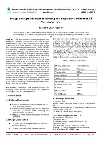
The rack and pinion mechanism were chosen for its simplicity, higher displacement of the wheels, and ease of packaginginthevehicle’stoebox.TheAckermansteering geometry was chosen considering the load transfer characteristics,corneringspeed,track characteristics,and required turning angle to achieve minimal turning radius withspecificwheelbaseandtrackwidthandtoachievethe perfectrollingofthewheels.TheAckermananglewasfound tobe25degreeswhichwasdesignedtoachieveanoversteer thatprovidessensitivehandlingcharacteristics.
1.3 Steering Calculations
Tanβ=kingpin–kingpincenterdistance/2xWheelbase β = 25°
Maxinnerwheelangle-Si=44°(consideringmaximumslip)
ByAckermanncondition
CotSo-cotSi=Trackwidth/wheelbase
Outer wheel turning angle So = 25.6°
Turningradiusofthewheel
Frontinnerwheel, Ri=wheelbase/Sin(Si)-(Trackwidth-K.k)/2
Frontouterwheel, Ro=Wheelbase/SinSi-Trackwidth-k.K)/2
Wherek.kisthekingpincentertocenterdistance RI = 1828.9 mm, RO = 2926.7 mm
Steering Effort Calculations
Totalweightofthevehicle=245kg
Onfrontaxle=40%ofW
OnRearaxle=60%ofW
Weightononewheelinfront=40%ofW=49kg
Torque on pinion = Weight on one-wheel x radius coefficientoffriction =49x9.81x21x0.7=7066.143N.mm
Torqueonpinion=7.066Nm
SteeringeffortTorqueonpinion=torqueonsteeringwheel Torque on steering wheel= steering effort (force given by driver)xRadius
7066.143=Fx(5x25.4)
F=55.63
Steering effort = 55.63 N
1.4 SUSPENSION DESIGN CONSIDERATION
To maintain maximum contact patch with the groundinallconditions,providinghighertraction, better handling, and comfort by isolating road shockswhileriding.
Toprovideminimumbodyrollwhilecornering.
Toattainminimumjackingforcebymanagingthe staticroll centerlocation.Unequal andUnparallel wishbone geometry is chosen to minimize the camberchangeduringcornering.
ThefrontTrackwidthofthevehiclewaschosentobe52”for betterstabilityandreartrackwidthwasreducedto48”for better traction during acceleration. The vehicle’s 18” inch groundclearanceprovidesthewheelverticalroomtotravel andabsorbshocks.
Thishelpsreducescrapingagainsttheobstaclesandreduces damage underbody. The negative camber aids in better handlingatcornersandthissetupisexpectedtooversteerin thetrackbecauseofthecamberanglespre-setatthefront.
1.5. Spring Rate Calculations
Sprungmass(front)=71.11kg/2 =35.55kg(onewheel)
Sprungmass(rear)=106.67kg/2=53.3kg(onewheel)
Forfront,ridefrequency(Rf)=1.6Hz
Forrear,ridefrequency(Rr)=1.8Hz
Springstiffness(K)=4×π^2×(Rf)^2×(Mf)×(Mr)^2 =4x(3.14)^2×(1.6)^2×(35.55)×(1.57)^2 =8847.04N/m=8.29N/mm
Motionratio(MRr)=D1/D2=431.8/253.05=1.70
Springstiffness(K)=4×π^2×(Rr)^2×(Mr)×(MRr)^2 =4×(3.14)^2×(1.8)×(53.3)×(1.7)^2 =19682.91N/m
Kr=19.165N/mm
1.6 Front Wheel Geometry
• FrontUprightweight:965g
• OverallheightofUpright:140mm
• Overallheightandlengthofupperballjoint mountingpointisreduced.
2. ANALYSIS
2.1 Multi Body Dynamics Analysis
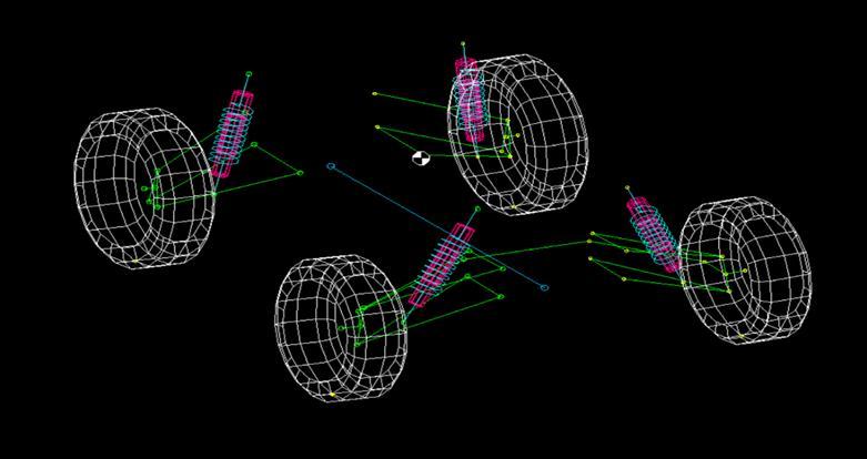
Multi-Body dynamics is done so that we can analyze how suspension and steering behaves during bump, and cornering. We have performed suspension analysis using LOTUSSHARKsoftwarewherewehavegivenparametersof bump travel to be 4 inches analyzed the response of the vehicle.
2.2 Finite Element Analysis
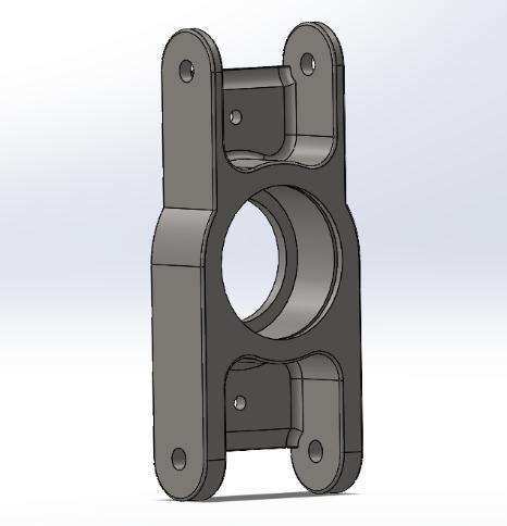
ANSYS provides a cost-effective way to explore the performance of products or processes in a virtual environment.Thistypeofproductdevelopmentistermed virtual prototyping. With virtual prototyping techniques, userscaniteratevariousscenariostooptimizetheproduct life before the manufacturing is started. This enables a reductioninthelevel of risk,andinthe cost ofineffective designs.
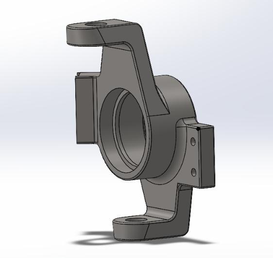
2.2.1 Maximum Braking Conditions on Front Knuckle
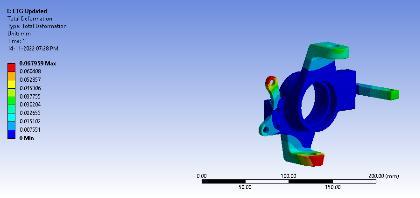
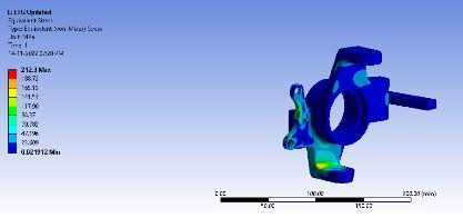
Thecenter part ofuprightisheldfixed,Forceof2200N is appliedatUppermountingpoint,forceof4400Nisapplied atlowermountingpoint,brakingforceof2600Nappliedat brake mount, braking torque of 230Nm is applied brake mountandsteeringforceof700Nisappliedatsteeringarm.
2.
2.2.2 Maximum Braking Conditions on Rear Knuckle
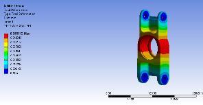
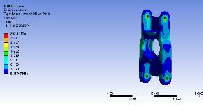
Uprightconnectsthewheelhubandthesuspensioncontrol arm.TheUpperandlowercontrolarmmountingpointsare heldfixedandverticalandcorneringforcesareappliedat the center. The maximum equivalent von mises stress obtainedintheanalysisis292Mpa.
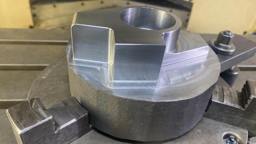
CNC (Computer Numerical Control) is a manufacturing processthathasrevolutionizedthewayproductsaremade. It involves the use of computerized machines that can preciselycutandshapeawiderangeofmaterials,including metals,plastics,andwood.TheuseofCNCtechnology has many benefits, including increased accuracy, consistency, andspeedofproduction.
OurproductismanufacturedusingCNC,itmeansthatthe entire process is automated and controlled by computer software.Themachineisprogrammedtofollowaspecificset ofinstructions,whichtellitexactlywhattodoandhowtodo it.Thisensuresthateachproductisidenticalandmeetsthe requiredspecifications.
4. RESULTS
From the overall design and the analysis of the front and rearknucklewehaveoptimizedthesuspensionsystemfor better off-roading and speed cornering. And the designed systemcantakehighimpactforceswhichisveryimportant foranall-terrainvehicle
The analysis of the control arm helps to understand the behaviorofthesuspensionsysteminheavyloading,braking, andcorneringconditionswhichhelpstostudythesystemin abetterway.
5. CONCLUSION
The design of a knuckle and control arm is critical to the performance,stability,andsafetyofavehicle’ssuspension system. The knuckle and control arm work together to support the weight of the vehicle, absorb shocks and vibrations, and provide steering control and stability. The knuckleisthecomponentthatconnectsthewheelhubtothe suspensionsystem.Ittypicallyhasaflangethatmountsto thehubandaspindlethatconnectstothecontrolarm.The knuckle must be designed to withstand the lateral and verticalloadsthataregeneratedduringcornering,braking, andacceleration.
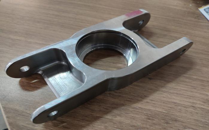
Whendesigningaknuckleandcontrolarm,severalfactors must be considered. These include the material selection, manufacturingprocesses,andthespecificloadsandforces thatthecomponentswillencounterduringoperation.Finite elementanalysisandothersimulationtoolscanbeusedto test and optimize the design, ensuring that it meets the necessarystrengthanddurabilityrequirements.
Additionally,thedesignofaknuckleandcontrolarmshould also consider factors such as ease of installation, maintenance,andrepair.Accesstocriticalcomponentsand ease of disassembly can significantly impact the cost and timerequiredformaintenanceorrepairs.
Inconclusion,asuccessfuldesignofaknuckleandcontrol arm requires careful consideration of many factors, includingstrength,durability,manufacturingprocesses,and maintenance requirements. A well-designed suspension systemcanimprovetheridequality,handling,andsafetyofa vehicle, reducing wear and tear on tires and other components,andenhancingtheoveralldrivingexperience.
REFERENCES
[1] ShripadMane“DesignandAnalysisofSuspensionand Steering system along with the Wheel Assembly of a BAJAATV”-InternationalJournalofInnovativeResearch inScience,EngineeringandTechnology
[2] Aditya Shahane, Manasi Kathale, Pratik Rathi and Ashank Gujar “KINEMATICS OF REAR SUSPENSION SYSTEM FOR A BAJA ALL-TERRAIN VEHICLE”International Journal of Mechanical Engineering and Technology(IJMET)
[3] DebiduttaMishra“BajaSAEUTEP2014DesignReportTeamJaabaz,VITUniversity–ResearchGate
[4] JasonBracco,ColemanDeAnda,JaimeDeschenesTara Olson,AustinSabbagha“SAEBajaFrontSuspension”Mechanical Engineering Laboratory the George Washington University School of Engineering and AppliedSciences
[5] SumitSharma“DesignReviewofSuspensionAssembly of a BAJA ATV” - International Research Journal of EngineeringandTechnology(IRJET)
[6] I. P. Dhurai “Optimization and Effects of Suspension Parameter on Front Suspension of SAE Baja Vehicle using ADAMS” - International Journal of Engineering Research&Technology(IJERT)