International Research Journal of Engineering and Technology (IRJET) e-ISSN:2395-0056

Volume: 10 Issue: 06 | Jun 2023 www.irjet.net p-ISSN:2395-0072
International Research Journal of Engineering and Technology (IRJET) e-ISSN:2395-0056
Volume: 10 Issue: 06 | Jun 2023 www.irjet.net p-ISSN:2395-0072
1Student, Mechanical Engineering. L.J. Institute of Engineering & Technology
2Professor, Mechanical Engineering, L.J. Institute of Engineering & Technology, Ahmedabad, Gujarat, India ***
Abstract - The Continuous Variable Transmission (CVT) system offers a solution that permits stepless gear ratio shifting regardless of the required speed and torque. Since its introduction a century ago, CVT technology has grown in popularity among luxury vehicles. However, CVTs are not widely used in machinery because of some limitations in the existing design. This study evaluates the CVT's design to identify its weakest point. Increasing the CVT's design efficiencyto extend its operationallife. The current designhas several issues that should be minimized, including noisy operation, jerkingwhile accelerating,andlackofawarenessof speed changes, expensive production, low belt life, and belt slidingafter a certainnumber ofcycles.Forthat,aSolidWorks CVT model has been made, andAnsys willbe used for analysis. The CVT V-Belt, which is built of composite material, is the subject of this study. As one of the transmission's major components, the performance of the belt under extreme conditions may provide insight into its long-term durability and performance. This study was conducted in five steps: review of the existing design, analysis of the existing design, design optimization, analysis of the revised design, and result comparison. The belt's material was changed to achieve an optimized design.
Key Words: Cvt, Solid Works, Ansys, V-belt
V-beltCVTsarepopularduetotheirlightnessandquietness, as well as their greater gearbox efficiency. They are commonlyusedinsmallautomobilevehiclesandhavebeen studied for their mechanics and efficiency [1, 2]. Gerbert lookedintotheoperationofV-beltsandfoundthatrubber CVT belt’s durability is the most important issue. The specifiedlifetime is25,000 km,soit isimportant to make recommendationsforenhancingfatiguestrength.However, sincerubberCVTbeltsaremadeofcompositematerial,itis difficulttoexplainthefatiguefailuremechanismforthese belts. CVT belts are subjected to high tension, bending deformation, and pulley friction forces, which can lead to fatiguefailure[3].Thecoedwasharmedbycyclicbending around the pulley, collecting fatigue damage from the synchronous belts. To strengthen the rubber CVT belts, detailedobservationsandmechanicalanalysisareneeded [5].
Wen-Fang Wu, Tyng Liu, and Chih-Hsien Wu conducted a failure analysis on the continuously variable transmission (CVT) system, which is one of the scooter’s major components.Theyidentifiedpotentialfailuremodesusing fault tree analysis (FTA) and failure mode, effect, and criticality analysis (FMECA). The impacts of component failureontheCVTsystemarehighlighted[6].
Hiroshilizuka,YoshikatsuOhta,AkihiroUeno,andTakeshi Murakam’s research on CVT V-belt examination uses experimentsandfiniteelementanalysis(FEA)todetermine the failure initiation point. FEA results show that as tooth load increases, stress initiation shifts from the working flank’soppositesidetotheworkingflankside.Thefailure initiation site is primarily determined by tooth load distributionontheworkingstressontheworkingflankside, whiletheloadnearthetoothtipcauseshighstressonthe oppositeside.Thebeltunderwentinitialstressafterlooping aroundthepulley,thegeneralmodelwasusedtoanalyzethe contactareaandtensiondistribution[6].
Thematerialofthepulleyismildsteel.Pulleyismadein 2Disks.
Thedensityifmildsteelis7860kg/m3 .
Centerdistancebetweenpulleys(C)=214mm.
Drivenpulleydiameter(Assuming)=195.5mm
Driving pulley diameter (d) =
DrivingPulleydiameter(d)=152.5mm
Variationindiameterofadrivingpulley(t) =(138.5-46.5)
International Research Journal of Engineering and Technology (IRJET) e-ISSN:2395-0056
Volume: 10 Issue: 06 | Jun 2023 www.irjet.net p-ISSN:2395-0072
=92mm
Variationindiameterofadrivenpulley(T) =(181.35-69.25) =112.1mm
PulleyGroveangle(α)=24˚
TotalDisplacementofdrivenpulley=(t/2)*tan(α/2) =(92/2)tan(12) =19.5mm
TotaldisplacementofDrivenPulley=(T/2)*tan(α/2) =(112/2)tan(12) =23.79mm
Dimension of Belt:
TheDunlopindustrialbeltscatalogprovidesthebelt’s specifications.Whichismentionedbelow:
Lengthofbelt=816mm
BeltGrooveangle=24˚
Massofbelt=0.5kg/m
MainCrossSection=33mmX10mm
Calculation of centrifugal force:
NMax=3800RPM
RMax =65mm
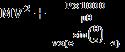
Centrifugalforce=mrꞶ2
ꞶMax=(2×π×N)/60=(2×π×3800)/60 =397.93red/sec


Consideringthemassofasmallerpulley900gm
Consideringthemassofabiggerpulley1800gm
Centrifugalforceofsmallerpulley
=(0.9×65×(397.93)^2)/1000 =9263.374N
Centrifugalforceofbiggerpulley =(1.8×65×(397.93)^2)/1000
=18526.74N
Belt Tension:
MassofBelt(m)=0.5kg/m
Coefficientoffrictionbetweenbeltandpulley(μ)=0.2
Powertransmitted(Poweroutputfromtheengine) = = =3979.35watt
Wrap angle of the driving pulley =180–sin-1( =168.50˚
Wrap angle of the driven pulley =180+sin-1( =191.49˚
Velocityofbelt= =38.86m/s
Tensioninslagside(T2)= [6]
Tensionintightside( )=T2 +P×1000/v[6]
Tension in slack side = 755.04 N

Tension in tight side = 103.250 KN

5.
TheimpactofCVToperationatmaximumtorqueonbeltlife andmaterial stressand deformationwill bestudiedusing static structural analysis in Ansys. The fatigue tool gives informationaboutthepossiblelifecyclesandsafetyfactors. After analysis of the rubber belt’s present material, new material, such as high-performance fibers, will be used to achievelowdeformation.
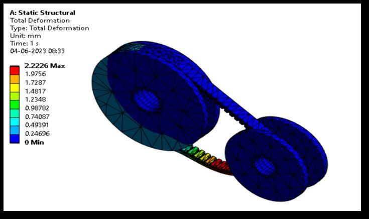
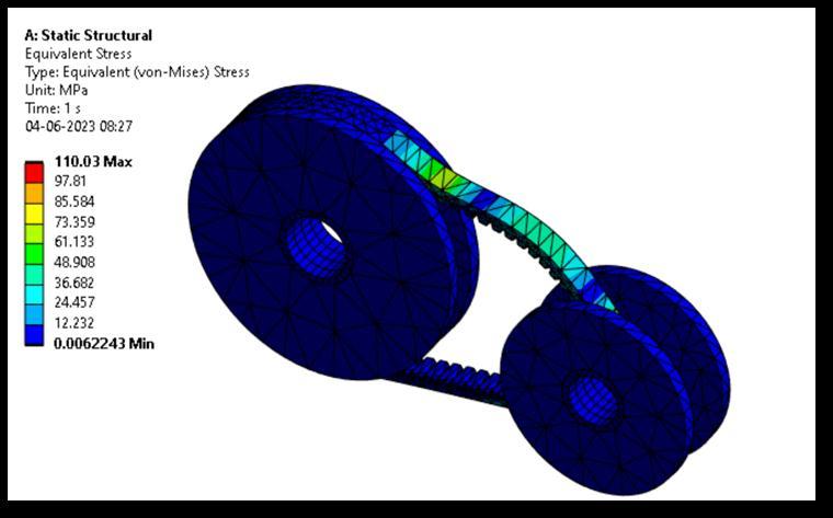
Themodelsimulatesbeltdishinginthepulleygroove,using materialconstantfromTable1.Thegeometryofthebeltand pulleyisdeterminedbytheshapeofthebeltandpulley.The stress-strain curve of the adhesive robber was expressed using the Neo-Hookean coefficient, C10. Reinforced rubber was handled like an anisotropic elastic substance. A truss elementreplacedtherope,andbelttensionwasappliedto the end of the rope. The wedged force and friction were appliedtothebeltsides,resultingina0.7frictioncoefficient onthesideface.[6]
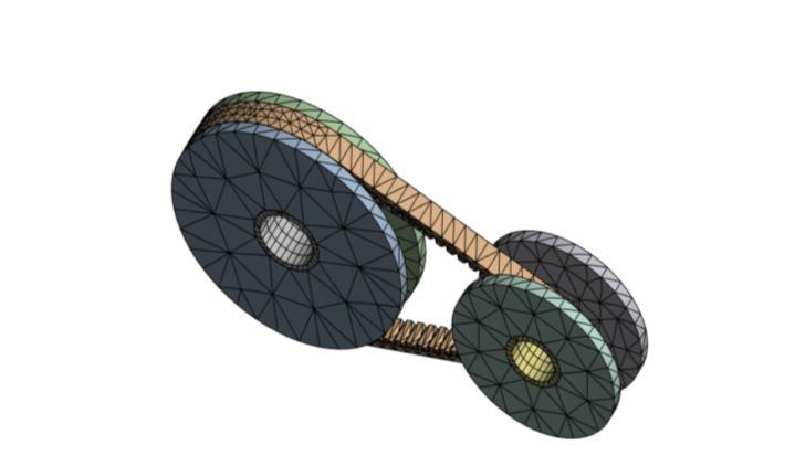
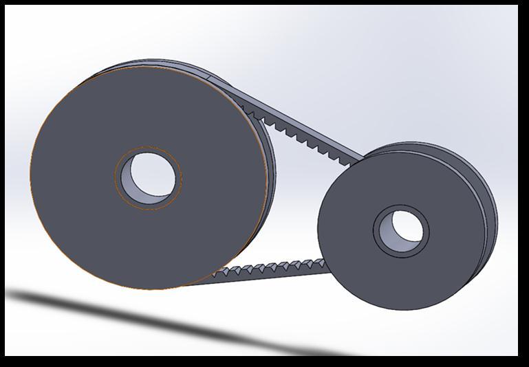
ThemethodinvolvescouplingaCVTwithmaterialattributes usingANSYSsoftware,producingvariousoutcomeslistedin Table1
1 Equivalent stress:
InusingtheANSYSsoftware,theCVTsystemmodelhasbeen developedandstaticallyexamined.
Analysisresultsshowmaximumstressis110Mpa.
2 Total Deformation:
resultshowmaximumDeformationis2.22mm.
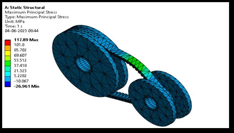
3 Maximum Principal Stress:
5.2
1 Equivalent stress:
result show maximum Principal stress is 117.89MPa
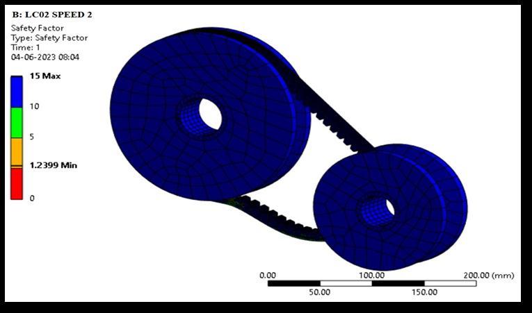
4 Factor of safety:
resultshowmaximumstressis98.57MPa.
2 Total Deformation:
resultshowfactorofSafety1.23
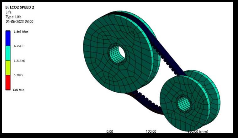
5 Life Cycle:
show maximum Deformation is 0.362 mm.
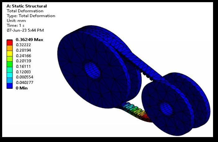
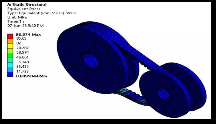
3 Maximum Principal Stress:
resultshowmaximumlifecycleis10^7
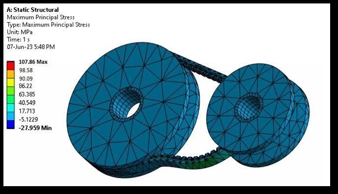
result show maximum Principal stress is 107.86 MPa
4 Factor Safety:
Analysisresultshowfactor
5 Life Cycle:
Safety1.35
Analysisresultshowmaximumlifecycleis10^9
Thedeformationobtainedforthe10Nmtorquecondition accountsforthemajorityofthedifferencesintheseresults. Whereasinthedeformationis0.362mmforKevlarand2.22 mm for rubber. And Life cycle for Kevlar is 10^9 and for rubberis10^7.
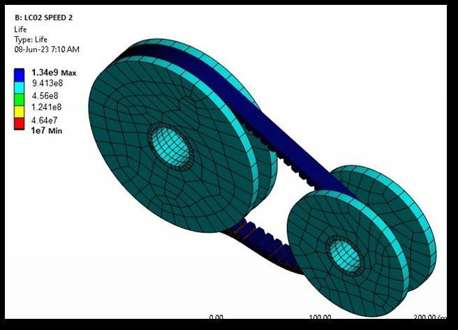
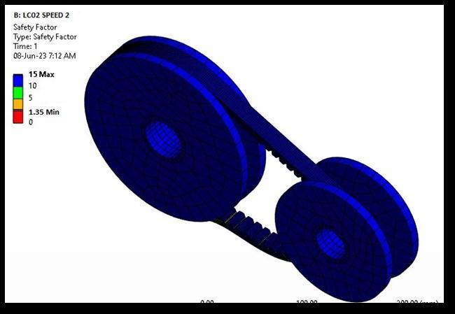
From the information above, it can be inferred that using Kevlar for a CVT belt will result in smoother operation because the material's overall distortion is much smaller thanthatofacordcomposedofnormalsteel.BecauseVbelts havethepropensitytolosetheirgripafteragivennumberof cycles, Kevlar also has a low elastic strain, which further indicatesthatitwillendureforlongerwithoutbeingfurther stretched. The Kevlar belt has a higher safety factor than steel cord, which also suggests that it will be stronger to handleheavywear.
We take this opportunity to express our gratitude to our lovingparentswhoarethecenterofourinspiration.
[1] Carbone,G.,Mangialardi,L.andMantriota,G.,2005,"The Influence of Pulley Deformations on the Shifting Mechanism of Metal Belt CVT", Trans. ASME, J. of
Mech.Design,127(January),pp.103-113M.Young,The TechnicalWriter’sHandbook.MillValley,CA:University Science,1989.
[2] Kanehara, S. and Fujii, T., 1997, "A Study on Metal Pushing V-Belt Type CVT (in Japanese)". The Japan. Society. of Mechanical. Engineers, 63(613), pp.32573264K.Elissa,“Titleofpaperifknown,”unpublished.
[3] L.Bertini,L.Carmignani,F.Frendo:“Analyticalmodel for the power losses in rubber V-belt continuously variabletransmission”MechanismandMachineTheory 78(2014)289–306,ELSEVIER,26April2014
[4] BernaBaltaa,b,FazilO.Sonmezc,Ꞷ,AbdulkadirCengiz d:“SpeedlossesinV-ribbedbeltdrive”Mechanismand Machine Theory 86 (2015) 1–14, ELSEVIER, 24 November201489-105.
[5] Hiroshi Iizuka, Akihiro Ueno, Takeshi Murakami “ FATIGUE FAILURE MECHANISM OF CVT RUBBER BELTS” Proceedings of the ASME 2007 International Design Engineering Technical Conferences & Computers and Information in Engineering Conference IDETC/CIE 2007 September 4-7, 2007, Las Vegas, Nevada, USA, DETC2007-34044
[6] Bansi Dalsania1, Kishan Patel2, Viren Gabani3, Ath S Singhal4,VivekDani5 “DesigningAndManufacturingOf Continuously Variable Transmission (CVT)” ISSN (PRINT):2394-6202,(ONLINE):2394-6210,VOLUME-2, ISSUE-5,2016