The examination and use of Solar Energy PV Power

Page 1

The examination and use of Solar Energy PV Power

Abstract - Based on the use of solar power in high-speed rail stations and canopy architectural design, PV power application has become a major research topic. Solar power is a key strategy to enhance the energy structure. This study analyses the PV power in domestic railway stations, compares independent and grid-connected systems, and solar battery systems. It then suggests two grid-connected systems using monocrystalline silicon panels and amorphous silicon thin film panels. The second plan is ultimately chosen, and engineering practice confirms its correctness and sanity. This is done while taking into account economic, energy-saving, environmental protection, and aesthetic concerns.

Key Words: PV power, independent system , gridconnected system, monocrystalline silicon panels, amorphous silicon thm film panels

1.INTRODUCTION

SolarPVenergyissecureanddependable,withbenefitssuch as minimal disruption, low failure rates, and simple maintenance.Inordertoreducethesevereenergycrisisand environmentaldamage,thisiscrucial.Sincetheenergycrisis ofthe1970s,everynationintheworldhasfocusedmoreon thedevelopmentofPVpowergeneration.Examplesinclude the Million Solar Roofs Initiative of the United States, the Sunshine Programme of Japan, the Million Solar Roofs ProgrammeofGermany,andtheBrightProjectofwestern China's provinces without electricity[1]. A type of optoelectronicdeviceknownasasolarbatteryusesthePV Effecttoconvertsolarenergyintoelectricalenergy.ThePV effect,whichoccurswhena deviceis exposedtolightand produces voltage in the cell between its electrodes and electrolyte[2],wasinitiallyidentifiedin1839bytheFrench experimental scientist Edmund Becquerel. Currently, the world's new solar battery research and development is concentratedontwoareas:efficientcrystallinesiliconsolar batteriesandvariousformsofthinfilmsolarbatteries.The conversion efficiency of efficient silicon solar batteries is closeto25%,andthatofefficientpolysiliconsolarbatteries isnownear20%.Betterlow-lightperformanceandrelative affordabilityarethin-filmsolarbatteryadvantages,butits major drawbacks are low efficiency and light-induced deterioration.

2. PV APPLICATION MODES

Thepowergenerationcapabilityisunstableduetosunset, badweather,andothernaturallimitations.Theindependent PV system and the grid-connected PV system are the two applicationmodesforsolarPVsystems.

(a)

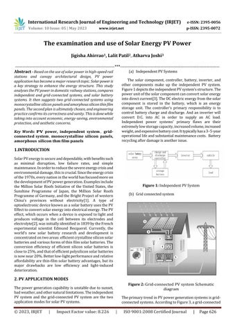
The solar component, controller, battery, inverter, and other components make up the independent PV system. Figure1depictstheindependentPVsystem'sstructure.The powerunitofthesolarcomponentcanconvertsolarenergy intodirectcurrent[3].TheDCelectricenergyfromthesolar component is stored in the battery, which is an energy storage unit. The controller's primary responsibility is to control batterycharge and discharge. And an inverter will convert D.C. into AC in order to supply an AC load. Independent power systems' primary flaws are their extremelylowstoragecapacity,increasedvolume,increased weight,andexpensivebatterycost.Ittypicallyhasa3–5-year operationallifeandsubstantialmaintenancecosts. Battery recyclingafterdamageisanotherissue.

International Research Journal of Engineering and Technology (IRJET) e-ISSN: 2395-0056 Volume: 10 Issue: 05 | May 2023 www.irjet.net p-ISSN: 2395-0072 © 2023, IRJET | Impact Factor value: 8.226 | ISO 9001:2008 Certified Journal | Page626
***
IndependentPVSystems Figure 1: IndependentPVSystem (b) Gridconnectedsystem Figure 2: Grid-connectedPVsystemSchematic diagram TheprimarytrendinPVpowergenerationsystemsisgridconnectedsystems.AccordingtoFigure3,agrid-connected

PV power generating system typically consists of a solar battery array[4], a grid-connected inverter, as well as monitoring and data sharing and data collecting tools. Assemble several solar battery modules in series and parallel in accordance with the necessary DC voltage and power generation, then install them on the roof or the groundtocreatethesolarbatteryarray.Inverterandgridconnected protection are the two main components of a grid-connected inverter. The inverter plays a part in electricityregulationbyconvertingtheoutputDCfromthe array into AC at the same voltage and frequency as the power network. The back-net-connectedinverter returns anyexcesselectricitytothegridwhenthePVsystemoutput exceedstheloadpowerdemand[5].Thegridsystem'scostis cheaperthanthatofastand-alonesystemanditsoperating and maintenance costs are substantially lower because it lacksabattery.

Figure 3: GridconnectedPVSystemstructure

TheuseofsolarPVtechnologyoughttoevolveinadirection that is scientific, environmentally friendly, useful, new, organic,healthy,progressive,andfuture-focused.Therefore, usingagrid-connectedPVsystemforasolarenergyproject atatrain stationisappropriate.Thissystemismorecosteffective,pollution-free,andenergy-efficient.Italsorequires lessroomforback-endequipmentandhasloweroperation andmaintenancecoststhanastandalonesystem.

ThisarticlecomparesthetwosolarPVschemesbasedonthe design of a rail station house roof in an example of some station,takingintoaccountthepresentdomestichigh-speed railstationhouseandcanopyarchitecturaldesignandthe requirementofsupplementalsolarenergypowersupply.

1) Grid-connected monocrystalline

silicon solar panel system

A. Grid-connected monocrystalline silicon solar panel systemcompositionandoperation:

Solararrays,wireboxes,AC/DCcubicles,three-phasegridconnected inverters, remote monitoring units, and other partsmake upa gridsystem.Solar battery arrays convert solar energy from light energy into direct current (DC), whichisthenchanged intothesamefrequencyandphase sinewavecurrentasthegridbythree-phasegrid-connected inverters.Surpluselectricityisthenfedintothegridinpart for the nearest local power supply. a) a grid-connected inverter,whichisprimarilyusedtoconvertDCpowerfrom PVpanelsintoACpower(DCIAC),thensupplieselectricity tothegridandpowerssolarcellsthroughaninternalpower regulatortomaximisefeedbacktothegrid;b)wireboxes, whichhavethefunctionofconvergingseveralsunraysinto oneormoresetsofoutputunitstomeettheneedsofvarious grid-connected inverter inputs; Grid input, grid power inverteroutput,andenergydistributionofsolarpanelarray DCpowerinputareall handledbyanAC/DCcubicle.Grid outputandpublicgridisolationarehandledbyanisolation transformer.Introductionstotheprimarycomponentsare presentedintableI,table2:

International Research Journal of Engineering and Technology (IRJET) e-ISSN: 2395-0056 Volume: 10 Issue: 05 | May 2023 www.irjet.net p-ISSN: 2395-0072 © 2023, IRJET | Impact Factor value: 8.226 | ISO 9001:2008 Certified Journal | Page627
Figure 4: Compositionandworkingprincipaldiagram
Item Value NominalPower(W) 170 Operatingvoltage(V) 44.2 Opencircuitvoltage(V) 44.2 Operatingcurrent(A) 4.82 Short-circuitcurrent(A) 5.27
3. PROGRAM COMPARISON AND ANALYSIS.

Table 2: MainparametersofGridconnectedinverter

TheprincipalDCpowerdistributionschemeparametersare as follows: Maximum PV input specifications are 145KW, 1000V,andDCover-voltageprotection.Note:Transformer for isolation: Model XNY-380 300G has a 300KVA output capacityandisgrid-connectedwithgridisolation.

B).Definitedesigns

The electrical system is built to accommodate a gridconnectedPVsystem.Arraydesignedtoensureefficientuse of the roof PV panels along the entire south side of the buildingcentreofthelayoutof1.620mwidebyPVpanel's band,choose170WPmonocrystallinesolarmodules,eachof whichhas18cellsconnectedinseriestoformaboardarray andhasapowerof3.06KW,makingupatotalof80arrays. Eight arrays and 80 sub-arrays require ten exchange line boxes (XNY-HX-8 / I) to provide one exchange line. It contains two 125kW three-phase inverters that are connectedtothegrid.Thesystem'soverallpoweroutputis 244.8KWP,withalayingareaof1858rn2anda250,000degree annual generation capacity. The triangular frame bracket, which has a strong wind resistance, convenient installation, and a simple structure, is used for the solar modules bracket in accordance with the characteristics of the railway station house. The bracket is made to be adjustable for elevation panels and appropriate for use at various latitudes. This system's features include network anddatacommunication,autonomousandresetcontrol,as seeninFigure5.

(2) Composition of an amorphous silicon thin film panel grid-connected system, as well as a description of its parameters.TheinstallationofPVpanelsonanamorphous silicon thin film solar system is unaffected by the original architectural design, and optical film can be adhered to fluorocarbon or polyester coated aluminium plate. Amorphoussiliconhasalowerphotoelectricconversionrate infineweatherthanpolysiliconandmonocrystallineplates, however three-layer membrane adhesion and a large absorption zone can compensate for this. When shielded from the sun's rays, bypass diode technology can neverthelessproducegreaterphotoelectricconversionrates. InFigure6,theoverallsystemflowisdepicted.

Figure5showsthatthesolarcell,junctionbox,andinverter make up the majority of this system; the solar cell differs frommonocrystallinesiliconcellsinthegridsystem.Quick connectterminalDCwater-resistantoutputlineof2.5mm2 witha560mmlengtharetheoutputlines;connectionacross each solar cell for bypass diodes; Durable ETFE (such as Tefzel) high transparent polymer for laminate encapsulation; Glue: microbiological inhibitor-infused ethylene propylene copolymer adhesive sealant; Battery type:ALUPLUSSOLARPVL-136,whichhas22triple-junction amorphous silicon solar cells connected in series with a dimensionof356x239mm.

International Research Journal of Engineering and Technology (IRJET) e-ISSN: 2395-0056 Volume: 10 Issue: 05 | May 2023 www.irjet.net p-ISSN: 2395-0072 © 2023, IRJET | Impact Factor value: 8.226 | ISO 9001:2008 Certified Journal | Page628 Length /width /thickness(mm) 1593/790/50 Weight(kg) 15.4
Item Value MaximumPVinputpower(kW) 125 MaximumPVinputvoltage(V) 900 ACoutputvoltagerange(V) 198-260 ACfrequency(Hz) 498-502 Maximumconversionefficiency 96% Current harmonicsTHD (kg) <4%
Table 1: ParametersofSolarPanel Figure 5: GridSystemcontroldiagram Figure 6: AmorphousthinfilmSolarsystemflowdiagram
145 NominalACoutputpower(kW)

Table 3: ParametersofSolarPanel

Thesolarlaminates'powerproductionexceedstheratings forthefirst8to10weeksofuse.Perhapsthenominalpeak wattoutputexceedsthe14%rating,theoperatingvoltage exceedsthe11%rating,andtheoperatingcurrentexceeds the4%rating.Poweroutputspecificationsarebasedonthe industry-standardtestwith1000W/m2irradiance,1.5air masses,and250°Ccelltemperatureinasteadyenvironment. Actual performance may differ by up to 10% in terms of output. Low temperature operation, the role of light intensity, and other associated operation may have an impactontheratedpoweroutput.Thesystem'smaximum operationalopencircuitvoltageislimitedto600VDCbyUL standards.

The energy conversion is finished in a box with this programmed,makingitaverycomprehensivesystem. The system also performs network and data communication,aswellasautonomousoperationand reset control. Along with the following qualities: The uselifeofafilmcapacitorisfourtimeslongerthanthat of other capacitors, and sophisticated and combinatorial calculations are used to guarantee maximumpowerproductioneveryhourofeveryday; fewerstandbyenergylossestoboosttheefficiencyof powertransmissiontotheutilitygrid;livelineareasto speed up installation and save money; no live connections required between the various components; When the system is in use, network control software restricts the flow of AC; extremely precisepeaktracking,withamendmentsmadethrough the back of each line; significantly more compact thoroughsystemtracking;fastisolationofthedefective PVlineviatheDCcontactor.

SchemeComparison

Item

3. CONCLUSION

ThisstudyintroducesthePVpowergenerationsystembased ontheanalysisandcomparisonoftheapplicationoftypical PVpowergenerationsystemandtherealcircumstancesof solarpowerprojectsforthehigh-speedrailstationbuilding. Thedemandforeconomicandenergysavings,aswellasthe functional qualities of scheme 2, encourage the ultimate selectionofscheme2inthisprojectbecausethereisalotof pavedspaceintheroofdesignandtheradiationintensityis relatively low where the station building is located. Engineeringpractisenotonlyvalidatesthecorrectnessand logic of scheme 2 but also demonstrates that the gridconnectedsystemofamorphoussiliconthinfilmsolarpanels iscapableofsupplyingreliableelectricitytohigh-speedrail stationbuildings.Inthemeanwhile,implementationofthe programmeishighlyoptimisticforthelong-termgrowthof thePVindustry,especiallyasitisagovernmentpolicytoget aroundtheenergybottleneckcausedbydomesticdemand and economic growth. The solar PV business has a vast amountofroomthankstonationalinfrastructuredesigned toenhancetheenergystructureandfullyutiliserenewable resources.

REFERENCES

[1] Wu Zhengjun. New and efficient solar cell design and performance[D]. Wu Xi: Jiang Nan University,2009:

[2] Martin Green Solar Works, processes and system applications[M].Xiuwen,Xie Hongli,Zhao Haibin, etc.Beijing: ElectronicIndyustryPress1987

[3] LuHuayong,Yuan Yue.Solar power technology [J]. Jiangsu Elec-trical Engineering, 2008,27 (I) :81-84

[4] Zhao. Solar PV power generation system [D]. Hefei:HefeiUniversityofTechnology,2003:9

[5] WangChanggui,Rong-QiangCui,ZhouHuangThe newenergygen-erationtechnology[M].Beijing: ChinaElectricPowerPress,2003:129

International Research Journal of Engineering and Technology (IRJET) e-ISSN: 2395-0056 Volume: 10 Issue: 05 | May 2023 www.irjet.net p-ISSN: 2395-0072 © 2023, IRJET | Impact Factor value: 8.226 | ISO 9001:2008 Certified Journal | Page629 Item Value NominalPower(W) 136 Operatingvoltage(V) 33 Opencircuitvoltage(V) 46.2 Operatingcurrent(A) 5.1 Short-circuitcurrent(A) 5.27 Length /width /thickness(mm) 5486/394/4 Weight(kg) 7.0
Scheme1 Scheme2 Solarpaneltype Monocrystalline silicon Amorphous silicon thinfilm Cell conversion efficiency 14%-165 8%-10% Designpower 244.8kWp 245kWp Pavedarea 1858m2 3885m2 Moduleefficiency 1yearofdecay<1% 1 year of decay 35% Rateofdecay 12 years of decay <10% 2yearsofdecay57% Weight(kg/m2) 15.4 7.0
Table 4: Schemecomparison

[6] Hemadez-Como.N,Morales-Acevedo. A. Heterojunction(HIT)siliconsolarcellmodelforAMPS-ID simulation[C]. In: Electrical Engi- neering, ComputingScienceandAutomaticControl,2008. CCE 2008. 5th International Conference on, Mexico, 2008, 449-454.

[7] Tanaka, M, Okamoto. S, Tsuge. S, et al . DevelopmentofHITsolarcellswithmorethan21 %conversionefficiencyandcommercia-lizationof highest performance HIT module[C]. PV Energy Con-version , Proceedings of 3rd World Conference on.Osaku,Japan,2003, 955-958.

[8] M.Powalla,M.Cememjak,J.Eberhardt,et al.Largearea CIGS modules: Pilot line production and new developments[J]. Solar Energy Materials and SolarCells,2006,90(18-19):3158 '3164.

[9] InyongMoon, KyunghaeKim, M.Thamilselvan, et al . Selective emitter using porous silicon for crystalline silicon solar cells[J]. Solar Energy Materials and Solar Cells, 2009, 93(6-7): 846850.

International Research Journal of Engineering and Technology (IRJET) e-ISSN: 2395-0056 Volume: 10 Issue: 05 | May 2023 www.irjet.net p-ISSN: 2395-0072 © 2023, IRJET | Impact Factor value: 8.226 | ISO 9001:2008 Certified Journal | Page630

Turn static files into dynamic content formats.

Create a flipbook