International Research Journal of Engineering and Technology (IRJET)
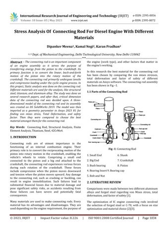
e-ISSN: 2395-0056
Volume: 10 Issue: 05 | May 2023
p-ISSN: 2395-0072
www.irjet.net
Stress Analysis Of Connecting Rod For Diesel Engine With Different Materials Dipanker Meena1, Kamal Negi2, Karan Pradhan3 1,2,3 Dept. of Mechanical Engineering, Delhi Technological University, New Delhi-110042
---------------------------------------------------------------------***--------------------------------------------------------------------the engine (work type), and other factors that matter in Abstract - The connecting rod is an important component the engine's working.
of an engine assembly as it serves the purpose of transferring energy from the piston to the crankshaft. Its primary function is to convert the linear, back-and-forth motion of the piston into the rotary motion of the crankshaft. The connecting rod primarily undergoes tensile and compressive loading under the cyclic engine process. In this project, Static analysis was done on the connecting rod. Different materials are used for the analysis, like structural steel, titanium, and aluminum alloy. The study was done on several research papers, and after that, critical dimension data of the connecting rod was decided upon. A threedimensional model of the connecting rod and its assembly was created on DS SolidWorks 2019. The model was then imported as a geometry parameter in Ansys 2023 R1 for finding von mises stress, Total Deformation, and safety factor. Then they were compared to choose the best material amongst them for the connecting rod.
In this research the best material for the connecting rod has been chosen by comparing the von mises stresses, total deformation and factor of safety of different materials on Ansys software. The connecting rod assembly has been shown in Fig –1. 1.1 Parts of the Connecting Rod
Key Words: Connecting Rod, Structural Analysis, Finite Element Analysis, Titanium, Steel, 42CrMo4.
1. INTRODUCTION Connecting rods are of utmost importance in the functioning of an internal combustion engine. Their primary role is to convert the reciprocating motion of the piston into rotary motion in the crankshaft, enabling the vehicle's wheels to rotate. Comprising a small end connected to the piston and a big end attached to the crankshaft, the connecting rod experiences various forces during each rotation of the crankshaft. These forces include compression when the piston moves downward and tension when the piston moves upward. Any damage to the connecting rod, such as cracking or buckling, can result in engine immobilization. Such failures lead to substantial financial losses due to material damage and pose significant safety risks, as accidents resulting from these failures can have severe and potentially fatal consequences.
Fig -1: Connecting Rod
|
Impact Factor value: 8.226
6. Shank
2. Big End
7. Crankshaft
3. Bush bearing
8. Piston
4. Bearing Insert 9. Bearing cap 5. Bolt and Nut
2. LITERATURE REVIEW Comparisons were made between two different aluminum alloys and forged steel regarding von Mises stress, total deformation, and factor of safety [1].
Many materials are used to make connecting rods. Every material has its advantages and disadvantages. They are used depending on the engine requirement, the purpose of
© 2023, IRJET
1. Small End
The optimization of IC engine connecting rods involved the selection of forged steel or C-70, with a focus on size optimization and material choice [2][3].
|
ISO 9001:2008 Certified Journal
|
Page 1034