STUDY ON STRUCTURAL COLLAPSE BEHAVIOUR OF REINFORCED CONCRETE BUILDING COLLAPSE STUDY
 Gaurav Verma1, Gajendra Singh2
1Research Scholar, Gaurav Verma, Department Civil Engineering, Himgiri Zee University, Dehradun
2Professor, Gajendra Singh, Department Civil Engineering, Himgiri Zee University, Dehradun ***
Abstract
Inthisstudy,thecollapseofareinforcedconcretetribunestructurewasanalyzedinordertodeterminethenextstepsfor repair. Both qualitative and quantitative methods were used, including visual observation, Hammer Test, and computationalmodelingwithStaadProv8i.Theresultsshowedthatthecollapseoccurredinthebeamsandfloor,leading to the conclusion that they should be demolished, while the columns could be repaired with minor modifications. The Hammer Test revealed a range ofconcrete quality, withthecritical stress occurringat the samelocationas thecollapse. The computational modeling with Staad Pro v8i confirmed that the reinforcement beam design was inadequate and the scaffolding used was too weak. It was concluded that the collapse was due to a combination of factors, including insufficient reinforcement design, unhardened beams and concrete, and inadequate scaffolding support during the concretehardeningprocess.
Keywords: reinforcedconcrete, reinforced concrete, rebound value, tribune
1. INTRODUCTION
Reinforced concrete construction is still the most widely used type of construction, this is due to the various advantages possessed by reinforced concrete. The structural advantages possessed by reinforced concrete are the combination of concrete and reinforcing steel that provide compressive strength as well as large tensile strength, In addition, this construction is easier to implement. This has led to reinforced concrete being widely used in construction projects that are of value or small value such as buildings, road pavements, bridges, dams , channels irrigation, ports, terminals,andsoon.
In the implementation of a building construction, there is often a failure of failure due to damage that occurs to the structureorpartsofthestructureatthetimeofitsimplementationstage oraftercompletionworkedon.Thisincidentis partlycausedbyfactorsthatwerenotpreviouslytakenintoaccount,suchaserrorsinplanningandimplementationanda burdenoverloadduetochangesfunctionsofthebuilding[1].
To obtain the causative factors of construction failure is not easy, sometimes the source of the failure itself is the accumulation of various factors. The source of construction failures is often influenced by natural factors and human behavior[2].
There are several test methods that can be used to investigate building structures including local non-destructive testssuchas ultrasonic testingand hammer tests andarehalfdamageordamagetotheoverallcomponentsofthebuilding testedintheformof load testing.
To further examine the collapse or failure of construction, this study will examine the case study of the collapse of reinforcedconcretestructure.Theobjectivesofthisstudyare:
1) Toidentifydamagetothecomponentsofthebuildingstructure;
2) Toknowthecapabilitiesofeachelementofthebuildingstructure;
3) TofindoutthecauseofthecollapseofthebeamsandflooroftheTribune;
2. RESEARCH METHODS
2.1. Literature Study
Literature studies are carried out by exploring material relevant to research, which includes various textbooks, scientificjournals,regulationsandNationalandInternationalStandards.
2.2. Research Method / Design
Thedesignoftheresearchthatwillbecarriedoutisasfollows:
a. Measurement of the degree of damage to the structure
Measurementofthedegreeofdamagetothestructurecanbedividedinto2parts,namely:
1) QualitativeMeasurement,carriedoutbyvisualobservationinthefieldThisobservationisareferencetothedata collectionofthestructurewhichincludes:
a) Technicalspecifications,contractdocuments
b) Measurementofthedimensionsofthestructureandelementsofthestructure
c) Workingdrawingsandasbuiltdrawings
d) Notes/implementationreports
e) Photosoftheimplementation
f) Recentphotosofstructures'locations,cracks,andfaults
g) Buildingusagereportifthebuildingiscompleted
h) Materialcontrolqualityreport
i) Eventsduringconstruction:sourceofmaterial,weather,changeofimage,etc.
j) Repairs(ifany)aftercompletionofconstruction
2) QuantitativeMeasurement,carriedoutbytestingaconcretehammer(HammerTest).
This measurement of the uniformity and quality of concrete is carried out against structural elements such as beams,columns ,andfloorslabs.
b. Observation Data Processing
Thedatathathasbeenobtainedfromtheresultsofvisualobservation,andthestrengthtestingofeachelementofthe structure will be analyzed to determine the degree of damage to the structure, so that the cause of the collapse of the buildingcanbeknown
c. Recommendations for Analysis Results
After knowing the category of the level of structural damage, a recommendation is made to repair a damage that occursormaybeifthelevelofdamageisverysevere,itcannotbedonerepairagain.
3. RESULTS AND DISCUSSION
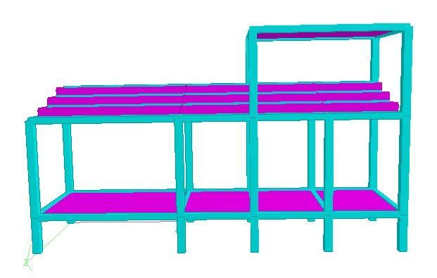
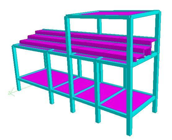
3.1. Analysis and Results of Visual Observations in the Field
Thestructuralcomponentsreviewedinthefieldbyvisualobservationare:
a) Ground Floor Concrete Beams and Foundations
• Thequalityofconcreteisnottested.
• Theentirebeamandfoundationarestillingoodconditionwithoutanycracks.
• Thedimensionsofthebeamthatarecarriedouthavebeeninaccordancewiththeworkingdrawings.
b) 1st Floor Concrete Blocks
• Thequalityofconcretewasnottestedbecausethebeamstructurecollapsed.
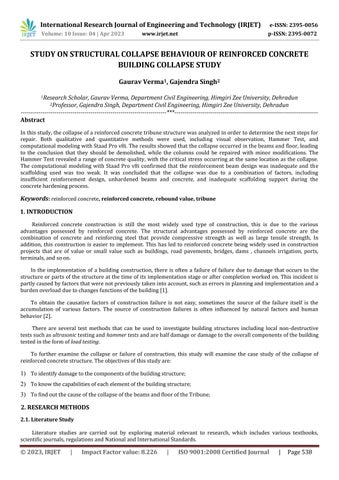
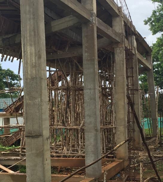
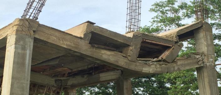
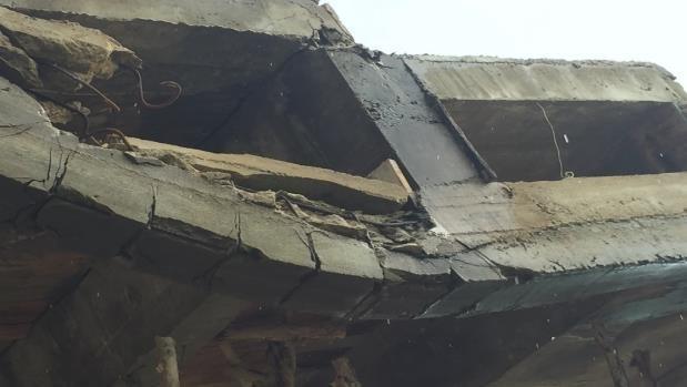
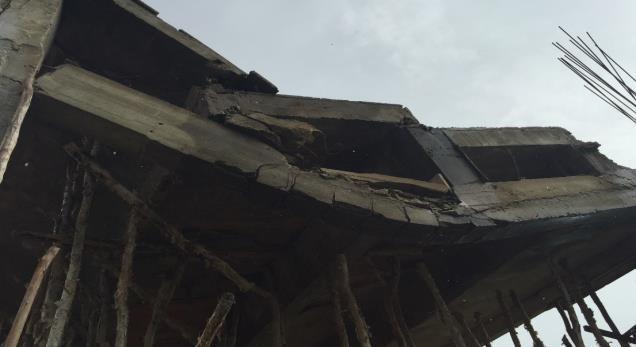
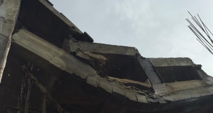
• All beams on the 1st floor have undergone deflection that exceeds the allowable deflection (L/180), and cracks thatareparaphonthepedestalandfield(middleofthespan)sothattheyarecategorizedcollapsed(seeFigure1).
• Noconcrete blanketshould be seen by atleast 40mm,this canreduce the durabilityoftheconcrete(seeFigure 2.a).
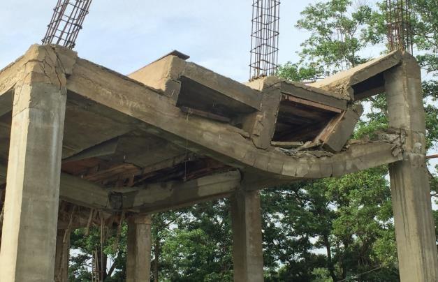
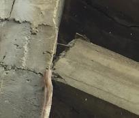
• The steel reinforcement that is fixed on the pedestal of the beam is too small (only 2 visible pull reinforcement) (seeFigure2.b).
• Thedimensionsofthebeam,thenumberofbendingandslidingreinforcementattachedhavecorrespondedtothe workingdrawing.
c) Concrete Floor Slabs
• Thequalityofconcretewasnottestedbecausethefloorslabstructurecollapsed.
• All concrete slabs on the 1st floor have undergone deflection that exceeds the allowable deflection (L/180), and severecracksinthepedestalandfield(middleofthespan)sothatcategorizedcollapsed(seeFigure1).
• Novisibleconcreteblanketshouldbeatleast20mm,thiscanreducethedurabilityoftheconcrete(seeFigure1).
• The suitability of the dimensions of the floor slab, the number of bending reinforcements that is attached has matchedtheworkingdrawing.
d) Concrete Columns
• TheconcretequalityofeachcolumnistestedwiththeHammerTesttool.
• There were 4 columns that experienced a slope due to being pulled by concrete floor blocks and slabs that had collapsed.
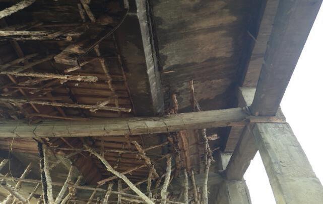
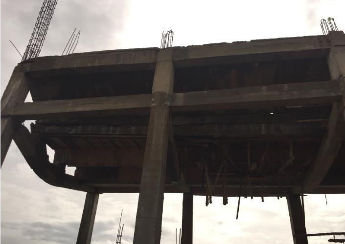
• The upper concrete at the confluence of beams and columns is severely cracked and crushed (see Figure 3.a), whiletheconcreteinthemiddleandlowerpartsisstillgoodnottohavecracks(seeFigure3.b).
• Thedimensionsofthecolumn,thenumberofbendingandslidingreinforcementattachedhavecorrespondedto theworkingdrawing.
3.2 Analysis and Test Results of Concrete Quality in the Field
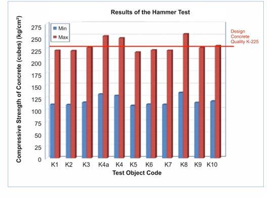
Testingthe qualityof concretein thefieldis carriedoutusing the Hammer Test tool.The result of the rebound value was 33,355 and the quality of concrete ranged from 116,640 kg / cm 2 sd. 229,780 kg / cm2 , this meansthat the quality uniformityofconcretequalityonthecolumncanbeisestimatedtobequitegoodaccordingtotheK225(225kg/cm2)(see Table1andFigure4)[4].Forconcreteonbeamsandfloorslabs,hammertestisnotcarriedout
Resume Good Enough Quality concrete K-225 meets
3.3 Collapse Analysis of Tribune Concrete Structure
Based on visual observations, it can be analyzed the possible factors causing the collapse as follows: a) Concrete Quality Factor
The quality of concrete column test results with the Hammer Test tool obtained a bounce value (Rebound) of 33,355 andthequalityofconcreterangedfrom116.64kg/cm2sd.229,780kg/cm2,thismeansthequalityTheuniformityof concretequalityinKolomcanbeestimatedquitewellaccordingtotheK-225plan(225kg/cm2).
b) Concrete Hardening Factor (concrete age)
According to regulation it is said that the determination of the quality of concrete √fc' must be based on testing concretethathasbeennutty28days[5].
Thiscanbepredictedbylookingattheconditionsinthefieldthatonlytheuppercolumnisseverelydamaged(cracked crumbly) while the columns in the middle and bottom no damage (cracks) (see Figures 4.a and 4.b), this means that thereisnofull-loadchannelingfromfloorslabstobeamsandfrombeamstocolumnsbecausetherelationshipbetween
c)
the concrete beam and column still does not have enough strength (the concrete is not old enough), while the scaffoldingisopenedtooquicklysothatthebeamandplatesufferedacollapsefirst.
Target Time Factor
Target time is the thing that most often makes workers, supervisors and implementers do a lot of carelessness. By lookingatthecontractthefairlyshortcompletiontimeoftheworkisas longas120daysitisverylikelytocausethe release of scaffolding and formwork of concrete work too quickly, the impact is that the structure experiences constructionfailurebecausetheconcretestilldoesnothaveenoughstrengthandstrengthtowithstanditsownweight.
d)
Concrete Column Strength Design Factor [6]
Thiscanbeseenwiththeconditionoftheconcretecolumnatthebottomwhichisstillgood(minordamageonlyoccurs tothetopofthecolumn dueto beingpulled by beams and slabs collapsed concrete)(seeFigure 3.a and 3.b), andthe dimensions of the concrete columns that meet the minimum size t (30 /30) in withstanding a load of 2 floors with a minimum capability Pu = 86,160 tons per column, so with 10 parts The total load that the Column can withstand is 861,600tonscomparedtothetotalweightofthebuildingof186tons.
e) Beam and Column Rebar Design Factors
Thiscanbeseenfromtheconditionoftheconcreteandthelackofthemainreinforcementofthebeampedestal(only 2D10 pull reinforcement is visible) in the relationship of the column beams that are unable to withstand load beams andfloorplates(seeFigure2.b).
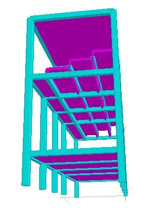
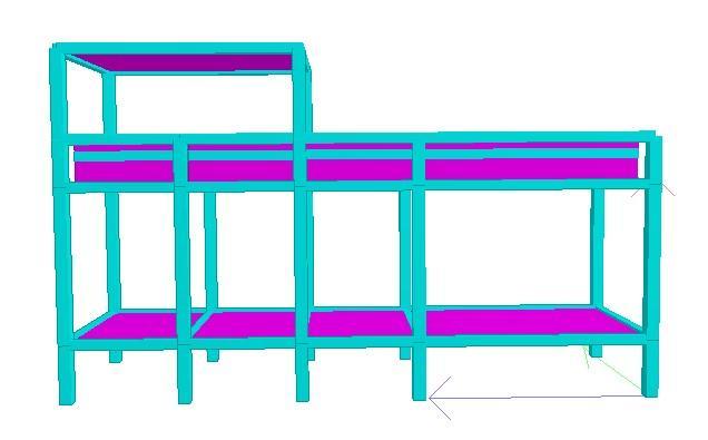
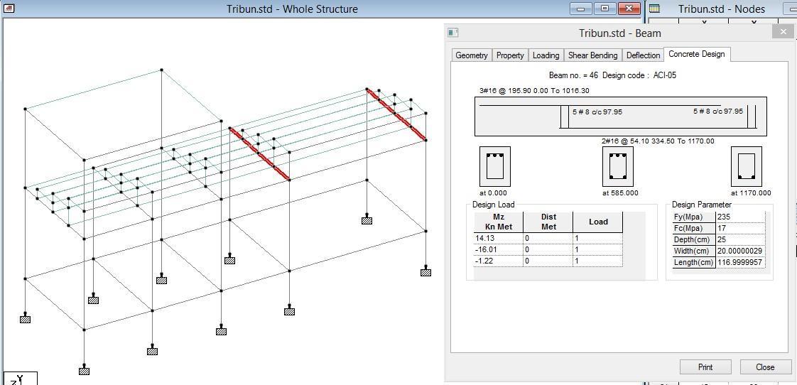
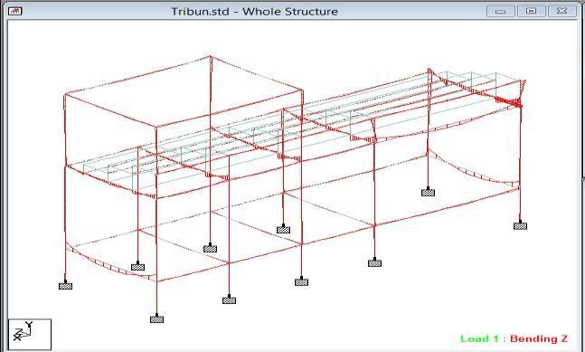
TofurtherexaminethecollapseoftheTribunestructuredesign,modelingwascarriedoutusingStaadProV8iSoftware (seeGambar6),withthefollowingresults:
1) Block Looping Design
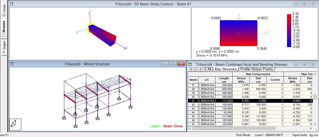
The maximum moment that occurs in the beam from the Staad Pro structure analysis only due to dead loads can be seeninFigure6.Thelocationofthebeam'smaximummomentwasalsothelocationofthecollapsethatoccurred.
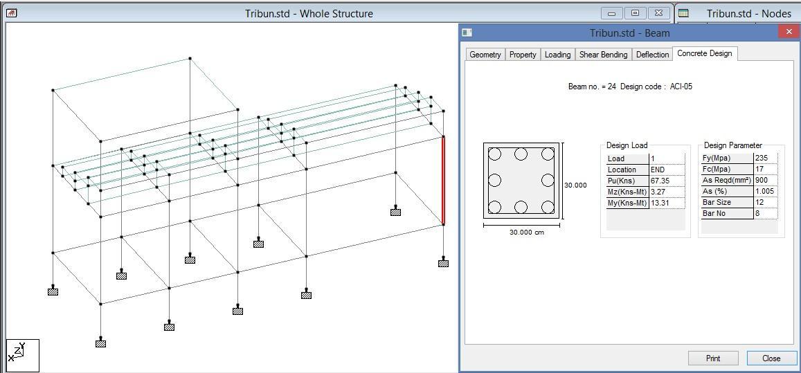
Theblock reinforcement designedby thesoftwaretocarrythe deadloadaloneis atleast3D12and3D16(see Figure 8), while in the working drawing and installed condition is 2D10 (see Figure 2.d), this means that the rebar of the attached beamdoesnotinflamedsothatitcanleadtothecollapseofthestructure.
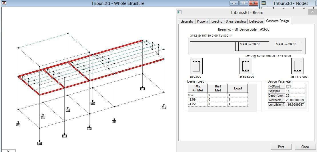
Fromthe resultsoftheanalysisof StaadProV8iSoftware,itcan beknownthe contoursofthevoltagethatoccursin the structural elements of the concrete plate, so that the location of the maximum voltage (red color) can be known. potentiallycrackingtothepointofcollapse(seeFigure8).
Locationofmaximumstress
concreteslabelementsresultingfrompotentiallyStaadProV8iSoftware
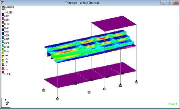
Inaddition,itcanalsobeknownthecontoursofthevoltagethatoccursinthestructuralelementsoftheconcreteblock,so thatitcanbeknownthelocationsofthemaximumvoltage(redbeamintheZdirection)thathasthepotentialfracturedto thepointofcollapse(seeFigure9).Thebeamshaveatensilestressvalueexceedingthetensilestressoftheconcrete permit(fr =0.7.√fc'=0.7.√17.67=2,942MPa).
2) Column Looping Design
Thecolumnreinforcementfromthesoftwaredesigntocarrythedeadloadaloneisatleast8D12(seeFigure10),whilein theworkingdrawingandinstalledconditionis12D12(seeFigure3.a),thismeansthatthereinforcementoftheterracing columnissufficienttocarrythedeadloadofthestructure.
f) Scaffolding and Formwork Strength Factor
Scaffoldingandformworkasabuffer,especiallyduringconcrete,areveryinfluentialonthesafetyofworkmanship.Ifitis notstrongenough,bothbecauseofthequantity,distance,andqualityofmaterials,itwillcauseadecreaseinthestructure, andthecollapseofthestructureduringtheconcretecastworkandtheprocessofhardeningit.
4. CONCLUSIONS
From the results of the analysis of field examinations and computer model simulations of the condition of the swimmingpoolconcretestandstructureafterexperiencingacollapse,itcanbeconcludedasfollows:
1) Overall the concrete columns are still in good condition (seen from cracks, slopes, and Hammer Test tests), with the exceptionofthecolumnsthataretilted.
2) Theentire1stfloorconcretebeamsandslabssufferedseveredamageandhadtobedemolished.
3) The approximate compressive strength of concrete on the column is 116.64 kg/cm 2 to 229,780 kg/cm 2, while the qualityofconcreteplanK-225(√bk'=225kg/cm2)(fromthehammertestresults).
4) ThecollapseoffloorslabsandconcreteblocksoftheTribuneismoredueto3factors,namely:
a) Thedesignfactorofrepeatingbeamsthatarenotcapableofcarryingtheload.
b) Factorshardeningblocksandconcreteslabsthatarestillnotoldenough.
c) Scaffolding strength factor that is unable to withstand the load of beams and floor slabs during the concrete hardeningprocess.
5. BIBLIOGRAPHY
[1]. Sanchez, K., & Tarranza, N. (2014). Reliability of rebound hammer test in concrete compressive strength estimation.Int.J.Adv.Agric.Environ.Eng,1(2),198-202.
[2]. Brencich, G. Cassini, D. Pera, and G. Riotto, “Calibration and reliability of the Rebound (Schmidt) Hammer Test,” CivilEngineeringandArchitecture,vol.3,pp.66-78,2013.
[3]. ACI350-01,“CodeRequirementsforEnvironmentalEngineeringConcreteStructures,”USA:ACI,2001.
[4]. Moaveni B, He X, Conte JP, Restrepo JI, Panagiotou M (2011) System identification study of a 7-story full-scale buildingslicetestedontheUCSD-NEESshaketable.JStructEng137(6):705–717
[5]. Adam, J. M., Buitrago, M., Bertolesi, E., Sagaseta, J., & Moragues, J. J. (2020). Dynamic performance of a real-scale reinforcedconcretebuildingtestunderacorner-columnfailurescenario.EngineeringStructures,210,110414.
[6]. Adam,J.M.,Parisi,F.,Sagaseta,J.,&Lu,X.(2018).Researchandpracticeonprogressivecollapseandrobustnessof buildingstructuresinthe21stcentury.EngineeringStructures,173,122–149.
[7]. General Services Administration (GSA), “Progressive collapse design guidelines for New Federal Office Buildings andMajorModernizationProjectsJune2003”
[8]. Osama Ahmed Mohamed and Omar Najm, “Outrigger Systems to Mitigate Disproportionate Collapse in Building Structures”, ELSEVIER, World Multidisciplinary Civil Engineering-Architecture-Urban Planning Symposium, pp. 839-844,2016
[9]. ZHANG Peng, CHEN Baoxu, “Progressive Collapse Analysis of Reinforced Concrete Frame Structures in Linear StaticAnalysisBasedonGSA”,IEEE,ThirdInternationalConferenceonIntelligentSystemDesignandEngineering Applications,pp.1074-1078,2012
[10]. J. M. Mirhom, H.T. Hafez, K.N. Ibrahim, J.R. Shaker, M. Abdel-Mooty, “Progressive collapse analysis of a highrise building considering the effect of an outrigger belt lateral load resisting system”, WIT Press, Structures Under ShockandImpactXII,pp.293-302,2012
[11]. Jinkoo Kim, Junhee Park, “Progressive collapse resisting capacity of building structures with outrigger trusses”, Wiley,Thestructuraldesignoftallandspecialbuildings,pp.566-577,2010
[12]. Huda Helmy, Hamed Salem, Sherif Mourad, “ComputerAided Assessment of Progressive Collapse of Reinforced ConcreteStructuresaccordingtoGSACode”,ASCE,Journalofperformanceofconstructedfacilities,pp.529-539, 2013
[13]. S. M. Marjanishvili, “Progressive Analysis Procedure for Progressive Collapse”, ASCE, Journal of performance of constructedfacilities,pp.79-85,2004
[14]. Tae-SungEom,HiubaltMurmu,WeijianYi,“BehaviourandDesignofDistributedBeltWallsasVirtualOutriggers forConcreteHigh-RiseBuildings”,Springer,IntJConcrStructMater,pp.1-13,2019
[15]. Han-Soo Kim, “Optimum Locations of Outriggers in a Concrete Tall Building to Reduce Differential Axial Shortening”,Springer,KimIntJConcrStructMater,pp.1-12,2018
[16]. Weng,X.2015. “Study on Collapse Patterns of Building Structures and the Distribution of Survival Room in CollapsedBuildingRuins.“InstituteofEngineeringMechanics,ChinaEarthquakeadministration.PhDDissertation.
[17]. Zareian,F., andH.Krawinkler.2010. “Structural System Parameter Selection Based on Collapse Potential of Buildings in Earthquakes.”Journal of Structural Engineering136 (8):933–943. doi:10.1061/(ASCE)ST.1943541X.0000196.
[18]. Zha,Z.2017.“Researchonbehaviorandfailureofreinforcedconcretewallsunderseismicload.”
[19]. Zhou,H., andJ.Li.2017. “Effective Energy Criterion for Collapse of Deteriorating Structural Systems.”Journal of EngineeringMechanics
[20]. People’s Republic of China National Standard. 2011. Code for Construction of Concrete Structures.Beijing:China Architecture&BuildingPress.