International Research Journal of Engineering and Technology (IRJET)
e-ISSN: 2395-0056
Volume: 10 Issue: 04 | Apr 2023
p-ISSN: 2395-0072
www.irjet.net
IMPACT OF REDUCTION IN STIFFNESS OF SLAB ON THE BEHAVIOUR OF RCC STRUCTURE Sneha S. Darekar1, Prof. P. R. Barbude2, Dr. S. A. Rasal3 1Post Graduate Student, Dept. of Civil Engineering, Datta Meghe College of Engineering, Airoli, Navi Mumbai
400708, Maharashtra, India
2Assistant Professor, Dept. of Civil Engineering, Datta Meghe College of Engineering, Airoli, Navi Mumbai 400708,
Maharashtra, India Assistant Professor, Dept. of Civil Engineering, Datta Meghe College of Engineering, Airoli, Navi Mumbai 400708, Maharashtra, India ---------------------------------------------------------------------***--------------------------------------------------------------------3
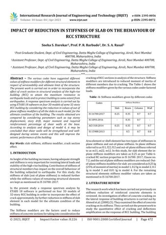
cracking of RCC sections in analysis of the structure. Stiffness modifiers are introduced to reduced moment of inertia of different members due to cracking. The Table-1 shows the stiffness modifiers given by the various codes under factored loads.
Abstract – The various codes have suggested different
values of stiffness modifiers for different structural elements in respect of serviceability and ultimate limit of the structure. The present work is carried out in order to incorporate the effect of crack section in structural analysis of the high-rise building (RCC) to attain the maximum resistance to earthquake loads and to protect building to some extent from earthquakes. A response spectrum analysis is carried out by using ETABS 18 software on four 3D models of same 32-story RCC building by considering the reduction in values of out of plane stiffness modifiers of all the slabs in each model, for the ultimate condition of the building. The results obtained are compared by considering parameters such as top storey displacement, story drift, major moment and required reinforcement percentage of shear walls at the base. According to analysis and design of model 4, it may be concluded that shear walls will be strengthened and welldesigned during seismic events and this will improve the seismic performance of the building.
Table -1: Stiffness modifiers given by different codes
1. INTRODUCTION As height of the building increases, having adequate strength and stiffness is very important for resisting lateral loads and stability of the high-rise building. Contribution of stiffness of structural members has impact on the overall behaviour of the building subjected to earthquake. For this study, the stiffness of slab (out of plane stiffness) is reduced further while the stiffness values of remaining structural elements are kept as mentioned in IS 16700: 2017.
Column
Wall
IS 16700:2017
0.25
0.35
0.7
0.7
IS 1893:2016
-
0.35
0.7
-
ACI 318:2014
0.25
0.35
0.7
0.7
IS 15988:2013
-
0.5
0.7
0.8
The research work which has been carried out previously on stiffness reduction of reinforced concrete elements is reviewed. An investigation of effect of concrete cracking on the lateral response of building structures is carried out by Ahmed et.al. (2008) (5). They examined the effect of concrete cracking on its stiffness. They carried out the present work to study the quantitative effect of cracking and deflections amplification on the response of RCC building. The building
The Stiffness modifiers are the factors used to reduce stiffness of concrete sections for taking into consideration the
Impact Factor value: 8.226
Beam
2. LITERATURE REVIEW
In the present study a response spectrum analysis by ETABS 18 software is performed on four 3D models of 32-story RCC building in order to incorporate the effect of crack approximately, by further reduction in stiffness of slab element in each model for the ultimate condition of the building.
|
Slab
Area element or shell element has two types of stiffnesses in plane stiffness and out-of-plane stiffness. In plane stiffness referred to as f11, f22, f12 and out-of-plane stiffness referred to as m11, m22, m12. In this study, for slab element the inplane stiffness modifiers are taken as 0.25 as per Table 6cracked RC section properties in IS 16700: 2017, Clause no. 7.2, and the out of plane stiffness modifiers are reduced. Outof-plane stiffness modifiers for slab are considered as 0.25 Ig (25% of moment of inertia) in model 1, 0.2 Ig in model 2, 0.1 Ig in model 3 and 0.01 Ig in model 4. For the remaining structural elements stiffness modifier values are taken as mentioned in IS 16700:2017.
Key Words: slab stiffness, stiffness modifier, crack section effect.
© 2023, IRJET
Stiffness Modifiers
Codes
|
ISO 9001:2008 Certified Journal
|
Page 472