International Research Journal of Engineering and Technology (IRJET)
e-ISSN: 2395-0056
Volume: 10 Issue: 04 | Apr 2023
p-ISSN: 2395-0072
www.irjet.net
Modeling of Solar System with MPPT Based Inverter Synchronization with Grid in Simulation Rahul Meshram1, Anita Singh2, Dimpal Zade3 1,2B.Tech Students, Department of Electrical Engineering 3Professor, Department of Electrical Engineering
Shri Sai College of Engineering and Technology (SSCET), Chandrapur, Maharashtra, India ---------------------------------------------------------------------***---------------------------------------------------------------------
Abstract - This paper presents a simulation study of a
synchronized with the grid. The paper discusses the modeling of the PV panel, MPPT-based inverter, and the grid, and presents the results of the simulation to demonstrate the effectiveness of the MPPT-based inverter in optimizing energy output.
solar photovoltaic (PV) system with a maximum power point tracking (MPPT) based inverter synchronized with the grid. The modeling of the solar PV system and the MPPT based inverter is performed using MATLAB/Simulink software. The simulation results demonstrate the effectiveness of the proposed MPPT fuzzy logic algorithm in maximizing the power output of the solar PV system. The inverter uses a switching strategy that combines sinusoidal pulse width modulation (SPWM). Additionally, the inverter is able to synchronize the output power with the grid, ensuring that the power injected into the grid is of high quality and does not cause any disturbances. The proposed system can be implemented in real-time to provide a reliable and efficient power generation system.
Overall, this research paper is a valuable contribution to the field of solar energy, providing insights into the design and operation of solar energy systems with MPPTbased inverters. The simulation model presented in the paper can be used as a tool for further analysis and optimization of solar energy systems, and it can help to promote the use of renewable energy sources for a sustainable future.
Key Words: Photovoltaic System, Maximum Power Point Tracking, Fuzzy logic Algorithm, Sinusoidal Pulse Width Modulation
1. INTRODUCTION Renewable energy sources are becoming increasingly important in today's world, and solar energy is one of the most promising sources of renewable energy. Solar energy systems have the potential to provide clean and sustainable energy for a variety of applications, including residential, commercial, and industrial use. However, to fully realize the potential of solar energy, it is essential to optimize the energy output of the system.
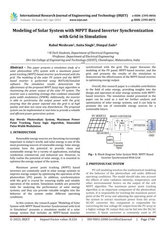
Fig – 1: Block Diagram Solar System With MPPT Based Inverter Synchronized With Grid
2. PHOTOVOLTAIC SYSTEM
Maximum power point tracking (MPPT) based inverters are commonly used in solar energy systems to improve energy output by optimizing the operation of the photovoltaic (PV) panels. In addition, synchronization with the grid is crucial for ensuring stable and reliable operation of the system. Simulation models are powerful tools for analyzing the performance of solar energy systems, and they can provide valuable insights into the behavior of the system under different operating conditions.
PV cell modeling involves the mathematical modeling of the behavior of the photovoltaic cell under different operating conditions. The model should take into account the effects of solar radiation intensity, temperature, and other environmental factors on the output of the cell. MPPT algorithm The maximum power point tracking algorithm is an important component of the photovoltaic system. It is responsible for tracking the maximum power point of the PV array and adjusting the operating point of the system to extract maximum power from the array. DC/DC converter this component is responsible for converting the low voltage DC output from the PV array to a higher voltage DC output that can be fed into the DC/AC inverter. A boost converter is commonly used in PV
In this context, the research paper "Modeling of Solar System with MPPT Based Inverter Synchronized with Grid in Simulation" presents a simulation model of a solar energy system that includes an MPPT-based inverter
© 2023, IRJET
|
Impact Factor value: 8.226
|
ISO 9001:2008 Certified Journal
|
Page 1740