
Performance Analysis of savonius hydro turbine using CFD simulation
Niteen Choudhary1 , Purushottam Sahu2 , Ghanshyam Dhanera3
1Reseach scholar, BM College of Technology, Indore

2Professor and HEAD BM College of Technology, Indore
3 Professors, BM College of Technology, Indore ***
Abstract - The primary goal of this study is to experimentally analyse the turbine's maximum efficiency. The goal of this research is to analyse the performance of a Savonius turbine utilised as a hydro turbine using computational fluid dynamics (CFD) simulations and experimental data. This project is primarily based on the renewable energy system.
Key Words: Fluiddynamics,hydroturbine,modelling,performance,andsimulation,alongwithcomputationalfluiddynamics
1. INTRODUCTION
Thecurrenteraistheeraofenergy.Energycanbeproducedbythewind,tides,sun,geothermalheat,biomass,includingfarmand animalwaste,aswellashumanexcrement,whichisknownasunconventionalenergy.Alloftheseresourcesarerenewableor limitlessanddon'tharmtheenvironment.Additionally,theydon'tdemandheavyuse.Currently,theworldusesupto20,000billion Kwh of energy, of which 70% is generated by conventional sources and the remaining 30% by sources such as hydropower, geothermal,biomass,solar,wind,andatomicenergy.About16%ofthis30%iscreatedthroughthekineticenergyoffallingor streamingwater,whichisthenconvertedintopower.
2. Lift Force Performance Model 3.1
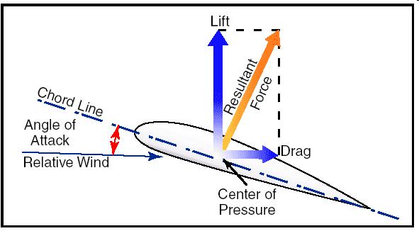
Let'sassumethat(L)istheliftingforce,whichactsinthedirectionofthefluidflow'snormal.Thisisexplicableusingthegoverning equation.
L=1/2C_(L)ρAV^2………………………………………(4.1)WhereAistheareaofthebladeairfoil,istheliftcoefficient,andisthedensity ofwater.PullForceDragforceisthenamefortheforcethatoperatesinthedirectionofflow.Drepresentsthedragforce.Thisforce ismostlycausedbythefluid'sviscosity.ThiscanbestatedusingtheformulaD=1/2AC_d(U-V).^2………………………………(4.2)where speedisV,dragforceisD,fluidvelocityisU,anddragcoefficientisCd.
WherespeedisV,thefluid'svelocityisU,thedragforceisD,andthedragcoefficientisCd.
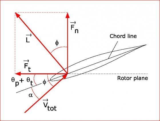
Typically,theliftanddragcoefficientvaluesareestimatedprovisionallyandcomparedtotheReynoldsnumber.InFig.3.2,aregion ofasharpedgeatspanIisindicated,togetherwiththeassociatedspeeds,powers,andedges.Theedgeoftherelativeliquidspeed totheplaneofrevolutionisdenotedby,andtherelativeliquidvectoratspanrisdenotedbyVrel.LandD,whichareguided oppositeandparalleltotherelatedliquidasappeared,speaktotheresultingliftanddragpowers.
Forthehighestlevelofskill,carefulconsiderationoftherotoredges'geometryandshapechangeisessential.Despitethefactthat freshairfoilsarerarelymadeforuseonrotors,turbineshavefrequentlyusedairfoilsthatareinspiredbyaeroplanewings.Airfoils usetheconceptofliftratherthandragtoharnessthepoweroftheair.Cuttingedgesthatuselift(powersagainstthedirectionof thestream)aremoreefficientthandragmachines.Ingeneral,usinglifthasresultedinsomebentandalteredshapes.
3. ANALOGOUS SIMULATION- I
Thegeometryforthetwo-bladedSavoniusturbineusedinthisprojectwasdevelopedinSolidWorksandimportedintotheANSYS 15workbench,whereadditionaloperationsincludingmeshingandsimulationswerecarriedout.
Modelling and Grid Size
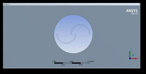
Thetwobasiccomponentsofthecomputationaldomainarethecoredomainandtheouterdomain.Tworotorswiththeright dimensionsandanappropriateaspectratiomakeupthemaindomain.Here,themotionlessouterdomaincontrastswiththe spinningprimarydomain.Thecomputationaldomain'sgeometryisdepictedinthefollowingfig.
3.2 NUMERICAL SIMULATION- II
Therangeoftheaspectratiohasbeenpickedfrom5to25,andanumberofgeometrieshavebeenoptimisedforthisnumerical simulation.AftercreatingallofthegeometryinSolidWorks,itisimportedintoANSYS15foradditionalnumericalsimulation.
Thegeometryofthesamesizewiththesamerotordiameterbutdifferentbladepositionsandproduceaworkablesolution.Inthis case,allofthegeometryiscalculatedusingthesameprocedureasinthepreviouschapter.
Belowfiguresshowthe5differentgeometryhavingdifferentaspectratio.
Results and Discussions
8.3.1 Velocity contour of savonius hydro-turbine at Aspect Ratio e=25 and canal width 0.636D, 2.5D, 5D, and 15D
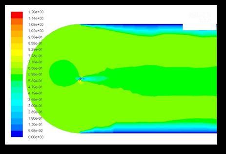
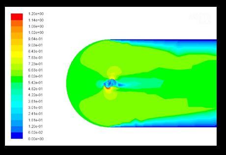
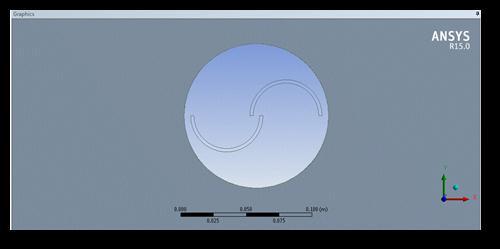
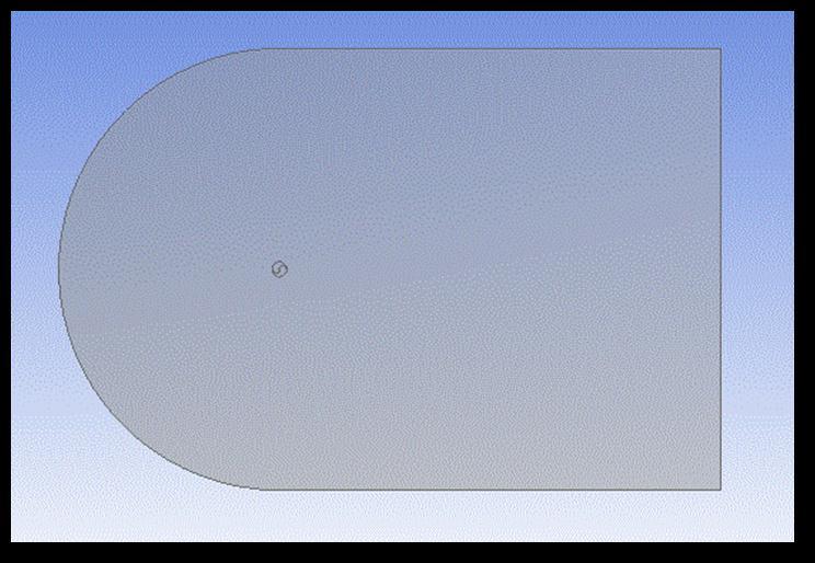
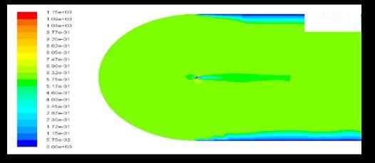
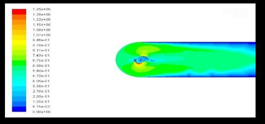
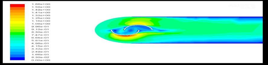
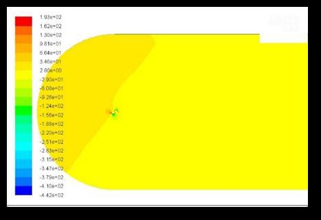
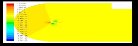
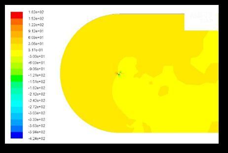
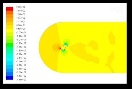
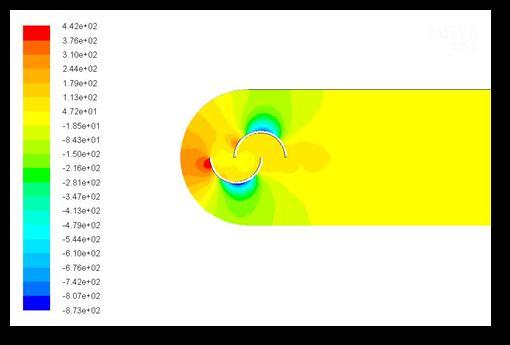
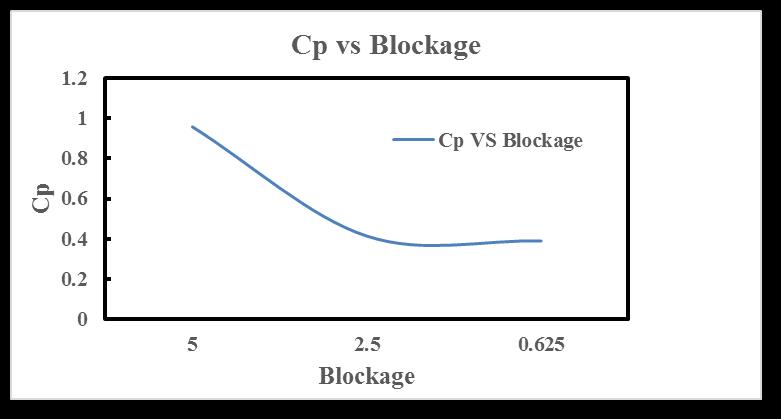 Fig 8.14 Pressure contour at 10D canal width
Fig 8.15 Pressure contour at 2.5D canal width
Fig 8.14 Pressure contour at 10D canal width
Fig 8.15 Pressure contour at 2.5D canal width
8.4 Closure
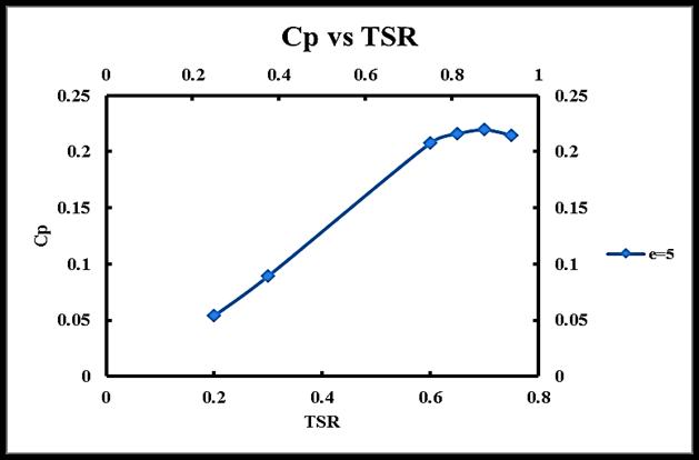
Thefig9.17showshowtheCpisvaryingwithrespecttocanalwidthitisanobviousobservationthatifthecanalwidthistoosmall thetotalforceofwaterwhichiscomingwithafreestreamvelocityisdroppedontherotorandthenwhileincreasingthewidthof theinletareathefluctuationiscontinueandatamiddlepositionabletogettheoptimumCpinthiscasethefeasiblesolutioncanbe abletogetat5D.Thewidthisminimizeatthelastpositionwhereitisunabletorotorfromaboveitisclearlyobservethatwhile reducingthewidthofthecanaltheCpisdecreasinggradually.
TheperformanceofaSavoniushydroturbineCFDsimulationisexaminedinthecurrentworkatlowvelocitiesintherangeof0.6 m/sinsideanopencanal.Forthesamesettings,resultsfrombothexperimentsandCFDworkarecompared.Theresearchresults aresummarisedinthefollowingconclusions:
1. The findings of the torque and power performance measurements of the Savonius hydro turbine indicate that the maximumCpcanbeattainedataspecificlocationwithalowfreestreamvelocitywithlessfluctuationintheturbine.
2. Thelocationdeterminedbythisworkisthemostpracticalsinceitallowsforamaximumpowerco-efficientthatisfar higherthanthatofanyotherposition.
3. Freestreamwatervelocityof0.6m/swouldbeidealforthecurrentworkbecauseitcanbeachievedwithlessfluctuating torqueandpower.
4. Astheoverlapratioincreases,itisseenthattheareasthatcoveralargerpercentageproducehighCpataspecificpoint, whichindicatesthatthepowerextractedthroughaSavoniushydroturbineisincreasinggradually.
5. TheCpisobservedtostartdecreasingate=30astheoverlapratioisfurtherraised,indicatingthate=25isthepractical pointfortheblade.
REFERENCES
[1] N.K. Sarma, A Biswas, R.D. Misra ,“Experimental and computational evaluation of Savonius hydrokineticturbine forlowvelocityconditionwithcomparisontoSavoniuswindturbineatthesameinputpower”Energyconversionand Managementatsciencedirect(2014)
[2] Zied Driss,Olfa Mlayeh Dorra Driss, Makram Maaloul, Mohamed Salah Abis “Numerical simulation and experimental valisation of the turbulent flow around a small incurved Savonius wind rotor” Energy at science direct (2014)
Theabovefig8.17showsthatastheblockageisreducethevalueofCpisincreasedandat5DwidthofthecanaltheoptimumCp canbeachieved. © 2023, IRJET | Impact Factor value: 8.226 |
International Research Journal of Engineering and Technology (IRJET) e-ISSN: 2395-0056
Volume: 10 Issue: 03 | Mar 2023 www.irjet.net
p-ISSN: 2395-0072
[3]PatelC.R.,PatelV.K.,PrabhuS.V.,EldhoT.I.,“InvestigationofOverlapRatioforSavoniusTypeVerticalAxisHydro Turbine”InternationalJournalofSoftComputingandEngineering(IJSCE)ISSN2231-2307,Volume-3,Issue-2,May (2013)
[4]N.H.Mahmoud,A.A.El-Haroun,E.Wahba,M.H.Nasef“AnexperimentalstudyonimprovementofSavoniusrotor performance” AlexandriaEngineeringJournal(2010)
[5]U.K.Saha,M.JayaRajkumar,“OntheperformanceanalysisofSavoniusrotorwithtwistedblades”RenewableEnergy 31(2006)1776
1788
[6]JoaoVicenteAkwaa,HoracioAntonioVielmob,AdrianePriscoPetry,“AreviewontheperformanceofSavoniuswind turbines”RenewableandSustainableEnergyReviews(2012)
[7] Sukanta Roya, Ujjwal K. Sahab ,“Computational study to assess the influence of overlap ratio on static torque characteristics of a vertical axis wind turbine” Chemical, Civil and Mechanical Engineering Tracks of 3rd Nirma UniversityInternationalConference(NUiCONE2012)
[8] Mabrouki,ZiedDriss,MohamedSalahAbis,“PerformanceAnalysisofaWaterSavoniusRotorEffectoftheInternal Overlap Ibrahim”Sustainable Energy, 2014, Vol. 2, No. 4, 121-125 Available online at http//pubs.sciepub.com/rse/2/4/1©ScienceandEducationPublishingDOI10.12691/rse-2-4-1
[9]. F. O. Rourke, F. Boyle, and A. Reynolds, “Renewable energy resources and technologies applicable to Ireland,” Renewable and Sustainable Energy Reviews, vol. 13, no. 8, pp. 1975–1984, 2009. View at Publisher • View atGoogle Scholar•ViewatScopus