International Research Journal of Engineering and Technology (IRJET)
e-ISSN: 2395-0056
Volume: 10 Issue: 04 | Apr 2023
p-ISSN: 2395-0072
www.irjet.net
AUTOMATED SOLAR WIRELESS CHARGING FOR ELECTRIC VEHICLE 1Pratik R. Fusate, 2Ayushi S. Gumgaonkar, 3Prashik S. Sadanshiv, 4Priyanshu D. Lengure, 5Tanvi S. Bijagare, 6Dr. A. M. Mendhe 1-5B.E. Students, 6Assistant Professor
Department of Electrical Engineering, Priyadarshini J. L. College of Engineering, Nagpur RTM Nagpur University, Nagpur, Maharashtra, India ---------------------------------------------------------------------***--------------------------------------------------------------------Abstract - Wireless charging of electric vehicles is an emerging technology that has the potential to revolutionize the way we
charge our vehicles. This technology eliminates the need for cords and plugs and allows for convenient and efficient charging. In this paper, we will discuss the concept of wireless charging, its history, working principles, circuits, features, construction and future prospects. Electric vehicles have now hit the road worldwide and are slowly growing in numbers. Apart from environmental benefits electric vehicles have also proven helpful in reducing cost of travel by replacing fuel by electricity which is way cheaper.
Key Words: Electric Vehicle, Automatic Wireless Power Transfer, Solar Power System, Dynamic Charging System, Battery Management System (BMS), Automated Solar Wireless Charging for Electric Vehicle
1. INTRODUCTION Electric vehicles have become more prevalent over the years due to the growing concern over climate change and air pollution. One of the main challenges facing electric vehicles is charging. Charging electric vehicles can be a hassle, requiring the use of cords and plugs. Wireless charging of electric vehicles provides an alternative to traditional charging methods. The idea of wireless charging dates back to the 19th century when Nikola Tesla first proposed the concept of wireless power transfer. Since then, many researchers have been working on developing wireless charging technology for electric vehicles. In 2010, the first wireless charging station for electric vehicles was demonstrated in Berlin, Germany.
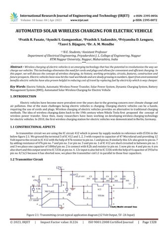
1.1 CONSTRUCTIONAL ASPECTS In transmitter circuit we are using the IC circuit 412 which is power by supply module in reference with t5336 in the below figure 2.1. We ground the terminal 5 of IC 412 and 1, 2, 3 with respect to capacitor of 47 Microfarad and providing 12 Volt input to the circuit to IC 412 with the help of 47k resistor to pin no. 1 and pin no. 8 similarly this 12v also given to pin no. 7 by adding resistance of 47k pin no. 7 and pin no. 3 or pin no. 3 and pin no. 1 of IC 412 are short circuited in between pin no. 1 and 3 we place one capacitor of 1000uf pin no. 2 is connect with 8.2k and resistor to pin no. 1 now pin no. 4 and pin no. 6 are also short and this output send it to IC 5336 at pin no. 4. 12v input is also fed to IC 5336 with the help of 4 capacitor of 393uf to pin no. 8,7,6,5 because it has shorted now, we place the transmitter coil L1 in parallel to those four capacitors.
1.2 Transmitter Circuit
Figure 2.1: Transmitting circuit typical application diagram (12 Volt Output, 5V- 2A Input)
© 2023, IRJET
|
Impact Factor value: 8.226
|
ISO 9001:2008 Certified Journal
|
Page 1328