
Design and Performance Analysis of an Inset Feed and Slot Configuration on Circular Patch Ultra-Wideband Antenna

Chanprit Kaur1, K K Verma2
1Research Scholar, Department of Physics and Electronics, Dr. Rammanohar Lohia Avadh University, Ayodhya , U.P. , India
2 Professor, Department of Physics and Electronics, Dr. Rammanohar Lohia Avadh University, Ayodhya U.P. India
***
Abstract - This paper presents a new design for a compact omnidirectional monopole antenna, suitable for broadband applications. The antenna features a modified circular patch, with a size of 40×45×1.6 mm3, and is simulated and fabricated using FR-4 substrate. The proposed design covers a frequency range of 2.4-11.24 GHz, which meets the UWB range of 3.110.6 GHz. The paper explores the effect of incorporating an inset feed on the circular patch. The resulting low-profile monopole antenna has a return loss of -27.94 dB and -31.07 dB, resonating at 3.38 GHz and 5.36 GHz respectively, which includes the WLAN and Wi-Max bands. The antenna's performance parameters, such as reflection coefficient, bandwidth, and radiation pattern, are simulated using CST2022 Microwave simulation software, and the results are compared with experimental data.
Key Words: Omnidirectional antenna, Inset feed, UWB antenna, Wi-Max, WLAN.
1. INTRODUCTION
Withtherapidexpansionofmoderncommunication,thereis a growing need for high data rates, reduced power consumption, and minimal interference with other communicationdevices[1].Ultra-wideband(UWB)antennas offer a wide bandwidth and are ideal for wireless communication systems due to their increased gain, simplicity,andhighdatarates[2].UWBtechnologyallows for short pulses in a broad range of frequencies with straightforwardstructures[3].ThedecisionbytheFederal Communication Commission (FCC) in February 2002 to authorizelowpowerwithlargebandwidthbetween3.1to 10.6 GHz has opened up numerous possibilities for broadbandapplications.Severalmethodshavebeenusedin theliteraturetoachieveUWBapplications,includinginset feed[7-9],taperfeed[10,11],CPWfeed[12],amongothers. The current study proposes the design of a circular monopoleantenna(40×45×1.6mm3)forUWBapplications, featuring an impedance bandwidth range from 2.411.24GHz. The impact of incorporating an inset feed and truncated ground on the antenna is also examined. The microstrip patch antenna presented in this study is compared to previous literature, demonstrating greater compactness,enhancedbandwidth,andincreasedgain.The antenna'sperformanceisfocusedonWLANfrequencies(2.9
to4.5GHz),Wi-MAXfrequencies(5.4GHzto6.45GHz),and VSWRvaluesbelow2.
2. ANTENNA DESIGN AND PERFORMANCE
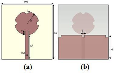
Theproposedantenna'sgeometryisillustratedinFigure1, displaying both its top view and bottom view, as seen in Figure 1(a) and Figure 1(b). The monopole circular patch antenna'sdimensionsareasfollows:awidthofWs=45mm,a lengthofLs=40mm,andasubstrate(FR-4epoxy)heightof T=1.6mm,featuringanepsilonvalueof4.3andalosstangent of0.02.ThecircularpatchhasaradiusofR=9.5mm,andits feed line has a length of Lf=20.3mm and a height of t=0.02mm. To modify the traditional circular shape, the antenna has three semicircular slots with a radius of r =1.75mm. To investigate the effect of inset feeding, the proposedantennawasmodifiedwithaninsetfeed,featuring a length of y=3mm and a width of x=0.5 mm, which was selectedafterparametricanalysistoensuregoodimpedance matchingof50Ω.Theothersideofthesubstrateisground. Thegroundstructureoftheproposedantennahasacopper material witha length of20mm,a width of40 mm, anda heightoft=0.02mm.Initially,thegroundstructurewasafullplanestructurewhichresultedinanarrowbandantenna.To improve the antenna's performance andconvert it intoan ultra-widebandantenna,thegroundstructurewasmodified to be partially grounded with the incorporation of three square slots with dimensions of 1×1 mm2. The simulated results of the return loss are shown in the figure, and the resonantfrequencyismeasuredwithareferencelineof-10 dB.
2.1
3.
Previous studies have explored various techniques for achievingcompactnessinantennadesign,asshowninTable 1[13-18].

3.1 FABRICATION AND VALIDATION OF PROTOTYPE
The proposed antenna was manually fabricated on a PCB usingthesamedimensionsasinthesimulation.Thefrontand backviewofthefabricatedantennaaredepictedinFigure. 4(a) and 4(b). The antenna's operating frequencies and radiating performance were validated in an anechoic chamber.


3.2 OPERATING FREQUENCY
Theantenna'soperatingfrequencies,whichrangefrom2.48.0GHz, were validated in an anechoic chamber using a networkanalyzer.Fig.5illustratesacomparisonbetweenthe simulatedandmeasuredresultsofthereflectioncoefficient.A minordiscrepancybetweentheresonancefrequencyofthe simulatedandexperimentalresultswasobserved,whichis attributable to the manual fabrication process. The measurementsetupisdepictedinFigure6.


Thecircularmonopoleantennaproposedinthisstudywas designedforUWBapplicationsusingCSTMicrowaveStudio2022.Toachieve a better impedanceof50Ω,aninsetfeed linewasused,andthegroundwastruncatedtoenablethe antenna tocover a bandwidth of 5.58GHz(2.42-8.00GHz) withareferencelineof-10dB.Byusingacircularpatch,the narrowband feature was overcome to make it suitable for broadband applications. The dual resonance covers the frequency range from 2.42 GHz to 8.00 GHz, with the first resonanceat3.4GHzforWLAN(from2.9to4.5GHz)andthe secondresonantfrequencyforWi-Max(from5.4GHzto6.45 GHz).Thereturnlosswas-27.96and-35.27dB,respectively, asshowninthe2Dpolarplotand3Dradiationpatternfor Far-fieldradiationat3.36GHzinFig.7(a,b)and(c,d).This omnidirectionalradiationpatternissuitableforbroadband applicationssuchaslocationconfirmation,radarapplication, remotesensing,etc.Themaximumgainachievedintheentire
Rangewasabout4dBi.Additionally,thestudypresentsthe relationbetweengainandfrequencyinFigure.8.
3.3 GAIN VERSES FREQUENCY

Fig.8 shows the simulated gain vs frequency curve of proposed antenna. From the graph it is observed that the averagegainis4.2dBiintheentirefrequencyrangesasgain isdirectlyproportionaltofrequency.

4. CONCLUSIONS
This work proposes a modified circular monopole UWB antennadesignedonanFR-4substratewithdimensionsof 40×45×1.6mm3 anda relativepermittivityof4.3andloss tangentof0.025.Thetraditionalcircularantennaismodified with three semicircle slots, and the partial ground is modifiedwiththreesquarecuts,makingithighlysuitablefor UWB broadband applications. The proposed antenna also features an inset feed, which provides good impedance matching of 50 ohm. The monopole microstrip patch provides enhanced bandwidth of 5.6 GHz, covering dual operatingfrequenciesof3.4GHz(WLAN)and5.3GHz(WiMAX).Themaximumgainachievedisabout4.2dBi,making itapplicabletovariousbroadbandUWBapplications.


ACKNOWLEDGEMENT
We are Thankful to Prof. B.T.P. Madhav for extending supportforthefabricationofasimulatedmicrostrippatch antennaattheK.L.University,Guntur.
REFERENCES
[1]Kumar,R.;Sinha,R.;Choubey,A.;Mahto,S.K.“Acompact microstripfeedlineprintedantennawithperturbedpartial groundplaneforUWBapplications.”InternationalJournalof RFandMicrowaveComputer‐AidedEngineering2021,31, e22764.
[2]Gopi,D.;Vadaboyina,A.R.;Dabbakuti,J.R.K.K.DGSbased monopole circular shaped patch antenna for UWB applications.SNappliedscience2021,3,198.
[3]Al-Gburi,A.J.A.; Ibrahim,I.M.;Zakaria,Z.;Zeain,M.Y.; Alwareth, H.; Ibrahim, A. M.; & Keriee, H. H. ‘’High Gain of UWBCPW-fedmercedes-shapedprintedmonopoleantennas forUWBapplications.’’Prz.Elektrotech2021,5,70-73
[4]Kundu, S.’’ Experimental study of a printed ultra‐wideband modified circular monopole antenna. ‘’Microwave and Optical Technology Letters, 61(5), 13881393.
[5] Mishra, R., & Tripathi, V. S.’’ A compact circular disc shaped monopole antenna for UWB applications. ‘’International Journal of Applied Engineering Research, 12(12),3049-3053.
[6]Ahmed,M.F.,Kabir,M.H.,&Islam,A.Z.M.T.PATCHAND GROUND PLANE SLOTS EFFECT ON THE RECTANGULAR PATCH MICROSTRIP UWB ANTENNA BANDWIDTH PERFORMANCE.
[7]Sarma,C.A.,Inthiyaz,S.,&Madhav,B.T.’’Effectofground etching,insetfeedandsubstrateheightonellipticallyshaped patchantenna.‘’change,15,19
[8]Hu,Y.,Jackson,D.R.,Williams,J.T.,&Long,S.A.‘’Adesign approachforinset-fedrectangularmicrostripantennas.’’In 2006IEEEAntennasandPropagationSocietyInternational Symposium(pp.1491-1494).IEEE.
[9]Samarthay, V., Pundir, S., & Lal, ’’Designing and optimization of inset fed rectangular microstrip patch antenna (RMPA) for varying inset gap and inset length.’’ International Journal of Electronic and Electrical Engineering,7(9),1007-1013.
[10]Kumar,N.,Singh,K.K.,&Badhai,R.K.‘’Ataperedfeed circular monopole super ultra-wideband (UWB) printed antenna.’’In 2016 international conference on communicationandsignalprocessing(ICCSP)(2016,April). (pp.1943-1946).IEEE.
[11] Lamultree, S., Jansri, C., & Phongcharoenpanich, C. ‘’Investigation of 3.1-10.6 GHz circular monopole antenna with modified partial ground plane. (2020).Przegląd Elektrotechniczny,96(4),49-52.
[12]Al-Gburi,A.J.A.,Ibrahim,I.M.,Zakaria,Z.,Zeain,M.Y., Alwareth, H., Ibrahim, A. M., & Keriee, H. H..’’High Gain of UWBCPW-fedmercedes-shapedprintedmonopoleantennas forUWBapplications.’’Prz.Elektrotech,5,70-73.
[13]Hossain,M.J.,Faruque,M.R.I.,&Islam,M.T.(2016). ‘’Design of a patch antenna for ultra wide band applications.’’Microwave and Optical Technology Letters, 58(9),2152-2156.
[14]Ling, C. W., Lo, W. H., Yan, R. H., & Chung, S. J. (2007). ‘’Planar binomial curved monopole antennas for ultrawideband communication.’’ IEEE Transactions on AntennasandPropagation,55(9),2622-2624.