Railway Track Geometry Surveying System
1,2,3,4 Students, Department of Electronics EngineeringShah and Anchor Kutchhi EngineeringCollege
Mumbai 400088, India
5,6 Professors, Department of Electronics EngineeringShah and Anchor Kutchhi EngineeringCollege
Mumbai 400088, India ***
Abstract- This paper represents design and implementation of Railway Track Geometry Surveying System On Railway tracks, any time the track strikes due to weather conditions, floods, earthquake, cyclone, etc. accidents happen. Nowadays most of the systems have some limitations, for example if a bridge or track is damaged, then that information goes to railway authority people, they notify and inform the corresponding trains which will take more time informing them.
So, to avoid delays and save time, our proposed system will immediately notify and inform the current train coming on the track through wireless medium using GPS and GSM module. This project is useful for avoiding the accident due to track geometry changes
Keywords: GSM Module, ESP32 Microcontroller, ESP32 Camera, GPS Module, Ultrasonic Sensor, Railway Tracks.
I. INTRODUCTION
The Indian railways provide the most affordable and convenient mode of passenger transportation, catering to both long-distance and suburban traffic. However, the occurrence of accidents on railways is often attributed to factorssuchasrailwaytrackcrossings,uneventracks,and undetected cracks. Therefore, there is a pressing need for robust,efficient,andsafetechnologiesfordetectingcracks inrailwaytracksandensuringproperalignment.
Ourprojectproposesadynamicapproachtorailwaytrack geometry and crack detection, utilizing sensor technology and a GPS tracking system. The ESP32 microcontroller is employed to control and coordinate the activities of the device. This innovative solution aims to send alert messages along with the geographical coordinates of the detected cracks, enabling prompt action to rectify the issueandensuretracksafety.
II. METHODOLOGY
Thissectiondiscussesabout hardwareandsoftwareused, developmentandworkingoftheproposedsystem.
A. HardwareSpecifications
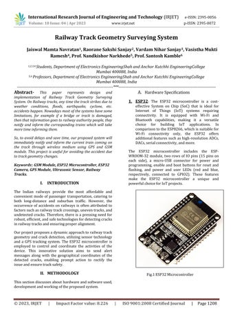
1. ESP32: The ESP32 microcontroller is a costeffective System on Chip (SoC) that is ideal for Internet of Things (IoT) systems requiring connectivity. It is equipped with Wi-Fi and Bluetooth capabilities, making it a versatile choice for building IoT applications. In comparisontotheESP8266, whichissuitablefor Wi-Fi connectivity only, the ESP32 offers additional features such ashigh-resolution ADCs, DACs,serialconnectivity,andmore.
The ESP32 microcontroller includes the ESPWROOM-32 module, two rows of IO pins (15 pins on each side), a micro-USB connector for power and programming, enable and boot buttons for reset and flashing, and power and user LEDs (red and blue, respectively, connected to GPIO2). These features make the ESP32 microcontroller a unique and powerfulchoiceforIoTprojects
1. GSM Modem: A GSM modem is a wireless modem designed to work with a GSM wireless network. It operates similarly to a dial-up modem, with the main difference being that a dial-up modem uses a fixed telephone line, whereas a GSM modem uses radio wavesforsendingandreceivingdata.SimilartoaGSM mobilephone,aGSMmodemrequiresaSIMcardfrom awirelesscarriertofunctionproperly.
A GSM modem can be an external unit or a PCMCIA card (also known as a PC Card) that can be inserted into a PC. AnexternalGSMmodemcanbeconnectedtoaPCusinga serial cable, USB cable, Bluetooth, or Infrared. Just like a GSMmobilephone,aGSMmodemalsorequiresaSIMcard fromawirelesscarrierforoperation.
GSMmodemsarecontrolledbyATcommandsissuedfrom a PC, similar to how a compatible modem is controlled. Thesemodemssupportan extendedsetofATcommands, whicharedefinedintheGSMstandards
2. GPS Modem: The Global Positioning System (GPS) is a worldwide, satellite-based, radio navigation systemthatwasdevelopedbytheU.S.Departmentof Defense for military purposes. It provides precise location information for vehicles regardless of their location, time, or weather conditions. The system comprises 24 satellites in orbit around the Earth, constantly monitored by earth stations. These satellitestransmitsignalsthatcanbedetectedbyGPS receivers installed in vehicles, allowing for highly accuratedeterminationoftheirlocation.
So,howdoesGPSwork?
Each GPS satellite broadcasts radio signals that enable GPS receivers in vehicles to estimate the satellite's locationandthedistancebetweenitandthevehicles.The receivers then use these measurements to calculate the vehicles' precise location on Earth, converting the calculations into geodetic latitude and longitude coordinates. To pinpoint a vehicle's position, a receiver typicallyrequiressignalsfromatleastthreeGPSsatellites.
3. Accelerometer (MEMS Sensor): The ADXL335 is a compact, slim, and energy-efficient 3-axis accelerometer that provides voltage outputs for measuring acceleration. With a minimum full-scale range of ±3 g, it is capable of detecting both static acceleration due to gravity in tilt-sensing applications and dynamic acceleration caused by motion, shock, or vibration.
One of the unique features of ADXL335 is its userselectable bandwidth, which can be adjusted using capacitorsattheXOUT,YOUT,andZOUTpins.Thisallows for customization to suit the specific requirements of the application, with bandwidth options ranging from 0.5 Hz to1600HzfortheXandYaxes,and0.5Hzto550Hz for theZaxis.
Inadditiontoitsversatileperformance,theADXL335also offersthreeanalogoutputsforXYZaxis,providingvoltage levelsthatcorrespondtoaccelerationvalues.Forexample, when powered with 3V, an output voltage of 1.5V indicates zero g acceleration. This makes ADXL335 a reliable choice for various acceleration sensing applications, with its unique features and performance capabilities.
Fig.5ADXL335Accelerometer
4. ESP32-CAM: The ESP32-CAM is a cost-effective development board based on the ESP32 microcontroller, featuring an onboard camera and compactsize.DesignedforIoTapplications,prototype constructions, and DIY projects, this board integrates Wi-Fi, traditional Bluetooth, and low-power BLE, poweredbytwohigh-performance32-bitLX6CPUs.
Withits7-stagepipelinearchitectureandon-chipsensors, including a Hall sensor and temperature sensor, the ESP32-CAM offers flexibility and versatility. Its main frequency can be adjusted from 80MHz to 240MHz, making it suitable for a wide range of applications. The board is fully compliant with Wi-Fi 802.11b/g/n/e/i and Bluetooth 4.2 standards, enabling it to function as a standalonenetworkcontrollerorasa networkingmodule forexistingdevices.
TheESP32-CAMfindsapplicationinvariousIoTscenarios, such as home smart devices, industrial wireless control, wireless monitoring, QR wireless identification, and wirelesspositioningsystemsignals.Withitswiderangeof capabilities and compact design, the ESP32-CAM is an ideal solution for diverse IoT applications, providing flexibility,performance,andcost-effectiveness.
5. OLED: Unlike LCD technology, Organic LightEmitting Diode (OLED) displays do not necessitate a backlight and are deemed as the ultimate technology for the upcoming era of flat panel displays. The compositionofOLEDdisplaysconsistsofanultra-thin organic film comprising numerous layers situated between an anode and cathode, both made up of electric conductive transparent Indium Tin Oxide. This multi-layered organic film comprises a Hole Transporting Layer, an Emission Layer, and an ElectronTransportingLayer.
Injectingappropriateelectrical voltageintotheOLED display initiates the injection of holes and electrons from the anode and cathode, respectively, which then combine to produce excitons. Subsequently, electroluminescence takesplace,whichistheglowingeffectobservedinOLED technology.
Volume: 10 Issue: 04 | Apr 2023
6. Ultrasonic Sensor: The principle behind ultrasonic sensors involves the use of ultrasonic waves to measure distance. The sensor emits an ultrasonic wave from its head and then receives the reflected wave from a target. By measuring the time elapsed betweentheemissionandreceptionofthewaves,the sensorisabletocalculatethedistancetothetarget.
Ultrasonic sensors operate by transmitting a sound wave at a frequency beyond the range of human hearing. The transducer within the sensor acts as both a transmitter and receiver of the ultrasonic sound. In many cases, including our ultrasonic sensors, a single transducer is usedtoemitapulseandreceivetheecho.
Todeterminethedistancetoatarget,thesensormeasures the time lapse between the emission and reception of the ultrasonic pulse. This unique method allows for accurate distancemeasurementusingultrasonictechnology
In the context of Arduino programming, the code written intheArduinoIDEiscommonlyreferredtoasasketch.To upload the sketch to the Genuino or Arduino board, it needsto beconnectedto theIDE.Thesketchesaresaved with the file extension '.ino', which is specific to Arduino programming. The Arduino IDE simplifies the process of writing and uploading code, making it accessible to both beginners and experienced developers in the Arduino community.
2. SoftwareSpecifications
1. Arduino IDE: The Arduino IDE is a freely available
open-source software used for writing and uploading code to Arduino boards. It provides an Integrated Development Environment (IDE) that is compatible with various operating systems including Windows, Mac OS X, and Linux. The Arduino IDE supports programming languages such as C and C++, making it aversatiletoolforArduinoprogramming.
2. PCB Design: In our PCB design process, weutilized the Express PCB software, which was downloaded from the internet. This user-friendly software provided a simple and straightforward approach to createPCBlayoutsforourproject.
The manufacturing of printed circuit boards (PCBs) involves several distinct steps. These steps include creating the circuit diagram, designing the PCB layout, creating the PCB artwork, transferring the pattern onto the board, etching the board, cleaning it, and finally drilling holes as needed. Each step plays a crucial role in the overall PCB manufacturing process, and careful attention is paid to ensure that each step is executed accuratelyandefficiently.
III. WORKING
i. Bend Detection of Track: In our railway track geometry system, we utilize a MEMS sensor to monitor the direction of the system. If the system detects any bend in the track through the MEMS
sensor, a message is promptly sent to the user specifying the exact location of the bend. The MEMS sensor is connected to the controller board, and any changes in its values are detected when a bend is detected in the track. All these sensors are connected totheappropriateGPIOpinsonthecontrollerboard. The controller board utilizes UART read to collect data fromtheGPSmodule,enablingustoaccuratelydetermine thelocationofthebendinthetrack.
ii. Crack Detection: In our railway track crack detection system, we utilize ultrasonic sensors to detect cracks on the track. If no echo sound is received by the ultrasonic sensor, it indicates the presence of a crack on the track. However, if an echosoundisreceived,itindicatesthatnocrackis detected. The output of the ultrasonic sensors is then fed to a microcontroller, which is also connectedtoGPSandmotordriverIC.
By employing ultrasonic sensors in our system, we are able to effectively detect cracks on the railway track by analyzingtheechosignals.Themicrocontrolleractsasthe centralprocessingunit,receivingandanalyzingtheoutput fromtheultrasonicsensors,andcoordinatingwiththeGPS and motor driver IC. Once a crack is detected, the system sends an SMS notification through the GSM module, providing real-time information about the location of the cracktoensurepromptactioncanbetaken.
IV. BLOCK DIAGRAM
ï‚· IntegrationofArtificialIntelligence(AI)andMachine Learning (ML): Railway track geometry systems can leverage AI and ML algorithms to analyze large amounts of data collected from sensors and other sources. This can enable more accurate and automated detection of track alignment issues, cracks, and other anomalies, as well as predictive maintenance capabilities for proactive repairs and maintenancescheduling.
ï‚· Mobile and Wearable Solutions: Mobile and wearabletechnologiescanbeintegratedintorailway track geometry systems, allowing maintenance crews to access real-time data and perform inspections on the go. This can increase flexibility, speed, and accuracy in track inspections, leading to moreefficientmaintenanceprocesses.
ï‚· Autonomous Inspection Systems: Autonomous inspection systems, such as drones or robotic vehicles, can be utilized for railway track inspections, reducing the need for manual inspectionsandenhancingsafety.Thesesystemscan collect data from various sensors and cameras, providing detailed and accurate information about trackalignmentandcracks.
VI. RESULT & DISCUSSION
Therailwaytrackgeometrysysteminourprojectutilizes both ultrasonic sensors and MEMS sensors to detect cracksandbendsonthetrack.Thevaluesobtainedfrom thesesensorsarethenpassedtothecontrollerboardfor further processing. Additionally, the GPS module is used totrackthelocationofabnormalconditionsonthetrack, and the coordinates are also passed to the controller boardfromtheGPSmodule.Finally,anSMSissenttothe user through the GSM module to notify them about the detectedabnormalcondition.
Fig.10 BlockDiagram
V. FUTURE SCOPE
The future scope of railway track geometry systems is promising, as advancements in technology continue to drive innovation in the field. Here are some potential futuredevelopments:
Our proect presents a cost-effective and robust solution totheproblemofrailwaytrackgeometrysurveying.The method employed is unique as it combines simplicity with novel ideas. Detailed technical and design aspects are discussed, along with a proposed railway track geometry surveying system. The implementation results are based on the utilization of simple components such as a GPS module, GSM modem, and MEMS-based track detectorassembly.Thisprojectshowcasesthesuccessful implementation of these components to achieve an efficient and effective railway track geometry surveying system.
VII. CONCLUSION
In conclusion, the railway track geometry system is a valuable tool that aids in ensuring the alignment and integrity of railway tracks. By employing advanced
technology, such as sensors, laser measurement, and dataanalysis,thissystemenablesaccurateandefficient inspectionofrailwaytracks,identifyingpotentialissues such as misalignment and cracks. It provides timely feedback to maintenance crews, allowing for prompt repairsandpreventingpotentialaccidentsordelays.
Theimplementationofarailwaytrackgeometrysystem can significantly improve the safety, reliability, and efficiency of railway operations, reducing the risk of accidents and minimizing downtime. In summary, the railway track geometry system is a crucial asset for railwaymaintenanceandoperation,supportingthesafe andreliabletransportation ofpassengersandgoodson railnetworks.
Furthermore, the railway track geometry systemoffersseveralbenefits,includingcostsavingsby identifyingissuesearlyandpreventingcostlyrepairsor replacements. It also helps extend the lifespan of railway tracks by detecting and addressing alignment problems and cracks in their early stages, preventing further deterioration. Additionally, the railway track geometry system enhances safety by reducing the risk of derailments and accidents caused by misaligned tracksorcracks.Italsoimprovesoperational efficiency by minimizing track maintenance disruptions, optimizingtrainspeeds,andreducingwearandtearon rolling stock. Overall, the railway track geometry system is a valuable tool for maintaining track quality, ensuring safe and efficient railway operations, and enhancingtheoverallperformanceofrailwaynetworks.
VIII. REFERENCES
[1] P. Lad and M. Pawar, "Evolution of railway track crack detection system," 2016 2nd IEEE International SymposiumonRoboticsandManufacturingAutomation (ROMA), Ipoh, Malaysia, 2016, pp. 1-6, doi: 10.1109/ROMA.2016.7847816.
[2] Josef Fuchs, Gabor Müller, Kamil Sazgetdinov, Erich Wipfler, Ingolf Nerlich. (2023) A methodology for alignment of measured rail profiles in turnouts as a basis for reliable vehicle/track interaction simulations. VehicleSystemDynamics61:3,pages821-837.
[3] Bhat, Shreetha & Karegowda, Dr & Noushad, Iqbal. (2021).SmartRailwayTrackMonitoringSystem.
[4] S. Srivastava, R. Chaurasia, S. Abbas, P. Sharma and N. Singh, "Railway Track Crack Detection Vehicle",International Advanced Research Journal in Science,Engineering and Technology, vol. 4, no. 2, pp. 145-148,2017.
[5] D.Narendhar Sigh and D. Naresh, "Railway Track Crack Detection And Data Analysis", vol. 5, no. 4, pp. 1859-1863,2017.
[6]GeorgeMathew,Mebin&A,Parvathy&Justus,Saji& Anil, Ajan. (2017). Automatic Rail Fault Track Detection forIndianRailways.10.1109/CESYS.2017.8321251.