International Research Journal of Engineering and Technology (IRJET)
e-ISSN: 2395-0056
Volume: 10 Issue: 04 | Apr 2023
p-ISSN: 2395-0072
www.irjet.net
Review of shaft failure in Coil Car Assembly Hemant Mali1, Omkar Nagothkar2, Prasad Swami3, Akanksha Kothawale4 1-4Department of Mechanical Engineering,D Y Patil College Of Engineering,Pune,India
---------------------------------------------------------------------***---------------------------------------------------------------------
Abstract - A spinning machine component known as a
which were built in 1964-1965[1]. The G41 has a capacity of 2000 LBS and can carry 6 coils in a single rack system. This G41 coil car has a self-weight of 59200 LBS. The G41 coil car has a total of eight wheels. G41 has a total length of 39 feet 2 inches and a width of 9 feet 8 inches. The central distance between the two wheels is three feet.
shaft transfers power from one place to another. Power transmission causes the shaft to receive torque, and reactions to the members it supports cause the shaft to receive a bending moment. The shaft was modified to include a discontinuity for crucial functional requirements. The shaft supports a variety of loading situations while it is in use (torsion, bending, axial, and combinations of these). In order to better understand failure and find ways to prevent it, a coil car shaft study was done. A visual inspection, hardness measurement, and investigation were carried out to determine the integrity of the failed axle shaft. The findings indicate that reversed bending fatigue caused the axle shaft to fracture and that fractures occasionally happened as a result of misalignment. A common cause of failure for many rotating equipment components is fatigue fracture.
2. LITERATURE SURVEY 2.1 Deepan Marudachalam M.G, K.Kanthavel, R.Krishnaraj: A shaft used in a spinning machine frequently fails, as discussed by Deepan Marudachalam M.G. Failure took place close to the shaft's change in cross section, where a relief groove is present. The forces and torques acting on the shaft are computed using the drive system to estimate the stresses occurring at the failure region. The findings of stress analysis using the finite element technique (FEM) are compared to the calculated values[2]. The least square approach is used to determine the stress concentration factors at the failure cross section from the fatigue stress concentration factors. According to Deepan Marudachalam M.G., changing the position of the support and increasing the shaft's fillet radii reduce the stress concentration factor while raising the endurance limit and fatigue factor of the shaft's safety.
We first check the load capacity of our existing shaft utilising theoretical and analytical techniques and typical shaft design calculations. Calculate the new shaft diameter in light of the findings. The load on the shaft considerably lowers as shaft diameter grows. The S-N curve is used to theoretically and analytically calculate the fatigue life of a shaft that is subject to cyclic bending stresses. Stress levels in the shaft steps were found to be greater during the shaft investigation. We examine the effects of fillet and chamfer on shaft life and use them to disperse load. Also, the effect of a larger load acting area on shaft life is examined in this study. Key Words: shaft failure, maintenance techniques, heavy loading, industrial application, analytical solution
1.INTRODUCTION A coil car is a material-handling device. This coil car instrument is frequently used in the steel and vital industries. The middle function of this type of material management tool is to load and sell off coils from mandrels. Transporting coils (or rolls) of sheet metal, most notably steel, is done with the help of coil cars, a type of rolling stock. The transport surface can be flat with support plates or specific elements, such as double-wedge cradles to support rounds such as ferrules or coils in the travel direction or also transverse, and one or more coils or rolls of straps with an anti-roll system can be included. These vehicles first appeared in the 1960s. Early examples include the Pennsylvania Railroad G40 and G41 class cars,
© 2023, IRJET
|
Impact Factor value: 8.226
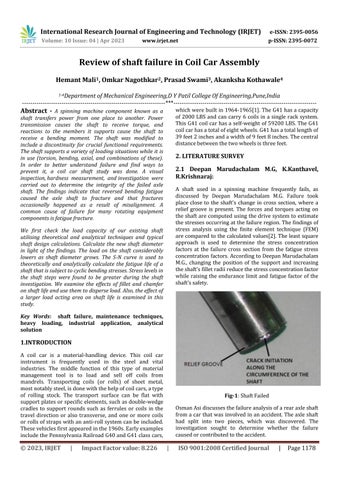
Fig-1: Shaft Failed Osman Asi discusses the failure analysis of a rear axle shaft from a car that was involved in an accident. The axle shaft had split into two pieces, which was discovered. The investigation sought to determine whether the failure caused or contributed to the accident.
|
ISO 9001:2008 Certified Journal
|
Page 1178