FEA ANALYSIS OF CAR RIM
Kishu Kumar1, Aditya Singh2, A.K. Madan31Under Graduate, Mechanical with Specialization in Automotive Engineering, Delhi Technological University, Delhi

2Under Graduate, Mechanical with Specialization in Automotive Engineering, Delhi Technological University, Delhi
3Professor, Dept. of Mechanical Engineering, Delhi Technological University, Delhi, India
***
Abstract - The rim is the "outer edge of a wheel, holding the tire". It makes up the outer circular design of the wheel on which the inside edge of the tire is mounted on vehicles such as automobiles. A standard automotive steel wheel rim is made from rectangular sheet metal. Design is an important industrial activity that influences the quality of the product being produced. The wheel rim is modeled by using the modeling software SOLIDWORKS. Later this modal is imported to ABAQUS for analysis. Static load analysis has been done by applying a pressure of 5N/mm2. The materials taken for analysis are steel alloy, Aluminum, Magnesium, and Forged Steel. The displacement that occurred to the rim is noted after applying the static load to different materials and maximum principal stresses were also noted, The FEA analysis shows that the stress generated in the optimized component is well below the actual yield stress of the Al alloy. The Fatigue life estimation by finite element analysis, under radial fatigue load conditions, is carried out to analyze the stress distribution and resulting displacement in the alloy wheels. S-N curve of the component depicts that the endurance limit is 90 MPa which is well below the yield stress of the material and safe for the application. The FEA analysis indicated that even after a fatigue cycle of 1020, the damage on the wheel is found only 0.2%.
Key Words: Wheel Rim, SolidWorks, ABAQUS, FEA Analysis, Static Load Analysis.
1. INTRODUCTION
The invention of wheels was a gift to humanity. The Mesopotamians are said to have invented the wheel around 3500 BC. Originally used to make pottery, it later becameanimportantmodeoftransportation.In3200BC, the Mesopotamians used the wheel to transport their chariots for the first time. Wheels became important elements that shaped today's advanced automobile industriesaftertheindustrialRevolution.Today,thereare many different types of wheels available on the market, and each one has a different movement and safety of the vehicle is the most important criterion in a vehicle and is standardizedandcertified.Wrappinganironbandaround thewoodenwheelsusedoncartsandwagonswasthefirst innovativeideaforimprovingawheel.Thepneumatictire was invented later, and it is still used on roads today in some form or another. Tire and rim improvements have
continued over the years, with inventions and enhancements of nylon, cord, rubber, and other materials tried out for various types of tires. As the world discovered steel, iron, and aluminum, and variations of thesemetals,aswellasvarioustypesofplastics,theactual rim or wheel was experimented with and changed in design and material. To be clear, plastics are not yet considered suitable for rim structure, but rather for cosmetic purposes, such as covering the rim and improving itsappearance. Alloywheelsare madefrom an aluminumormagnesiumalloy.Alloysaremetalandother element mixtures. They are typically stronger than pure metals, which are much softer and more ductile. Aluminum and magnesium alloys are typically lighter for thesamestrength,have better heatconduction,andoften have a more aesthetically pleasing appearance than steel wheels. Although steel is an iron and carbon alloy, the term "alloy wheel" is usually reserved for wheels made from nonferrous alloys. Alloy wheels are also purchased foraestheticreasons,eventhoughthecheaperalloysused are typically not corrosion-resistant. Alloys allow for the use of appealing bare-metal finishes, but these must be sealed with paint or wheel covers. Even if properly protected,thewheelsinusewillcorrodeafter3to5years, but refurbishment is now widely available at a cost. Intricate, bold designs are also possible thanks to the manufacturingprocesses.Steel wheels,ontheotherhand, are typically pressed from sheet metal and then welded together (often leaving unsightly bumps), and must be painted to prevent corrosion or hidden with wheel covers/hub caps. Static analysis of wheel rims made of materialssuchasaluminumalloy,steelalloy,andstainless steelis performedinthiswork.Afiniteelementmethodis a powerful tool or numerical procedure for obtaining solutions to many engineering analysis problems. A complex region defining a continuum is discretized into simple geometric shapes called finite elements in this method of analysis. The domain under consideration for the analysis is divided into a number of finite elements. Over these elements, the material properties and the governing relationship are considered and expressed in terms of unknown values at the element corner. The hub will be subjected to static analysis of wheel rim constraints. The hubwill be subjectedtostaticanalysisof wheel rim constraints. The wheel rim is modeled in
SolidWorks software and then imported into ABAQUS softwareforstaticanalysisinthiswork.
2. METHODOLOGY





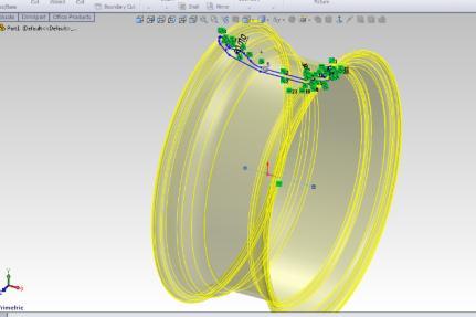
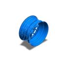
We studied several reputable and international journals and discovered that rims also fail due to improper materialselection.Towithstandforcedstressesandavoid major deformation, the rim material should be ductile. To investigatethevariousrim materialsThe3Dmodel ofthe WheelRimisrequiredfirst.WeusedSolidWorks,whichis averypowerfulsoftwareforcreatingcomplextocomplex structures. Here is our model, which we created in Solid Works.
1) SOLIDWORKS
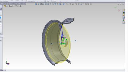

Solid works is a computer-aided design programme that can be used for both professional and personal purposes. While CAD software is known for being difficult to use, Solid Works is known for being user-friendly and simple to use. Solid works EPDM securely stores your design work. You can build 2D and 3D structures, as well as common models. We used various tools to create the 3D Model of the Car Wheel Rim of the Solidworks Software 2021 Version. Modeling becomes much easier for us with thehelpofthesetools.Someofthetoolsweusedwereas follows: Revolve, Extrude, Section View, Render, Trim, SymmetricMultiplications,andsoon.
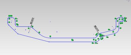
Step 1: First,westartwiththe2Ddrawingofthemodel.
2) ABAQUS
Dassault Systemes SIMULIA's finite element analysis software is called Abaqus. The software suite provides precise, robust, and high-performance solutions for difficult nonlinear problems, large-scale linear dynamics applications,androutinedesignsimulations.

Step 2: Use a Revolve Command to make this outer part of the rim.
Step 3: Takingitscross-section,wedrewthe2Dsketchofitsfront view.
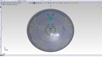
Step 4: Use circular pattern command and make your selection accordingtohowmanyarmsyouwanttodoyourrim.

3. MODELLING
HereweusedSolidWorksforthecomplexmodelingofthe Car wheel Rim for which at many steps we used various kinds of functionaries of the SolidWorks Software. We madethemodelinthefollowingsteps:
Step 5:
By Using Trim Command, cut the body as per the marked area.
4. RIM NOMENCLATURE
a) Wheel: The wheel is generally composed of a rim and disc.
b) Rim: Thisisapartwherethetireisinstalled.
c) Disc: This is a part of the rim where it is fixed to the axlehub.
d) Offset: This is a space between the wheel mounting surfacewhereitisboltedtothehubandthecenterlineof therim.
e) Flange: The flange is a part of the rim that holds both bedsofthetire
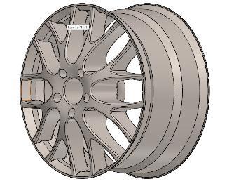
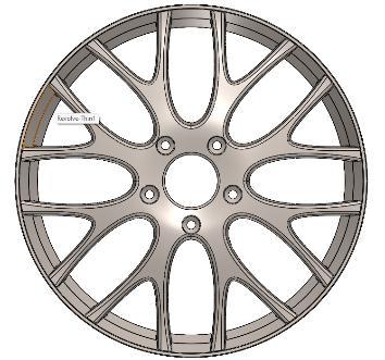
Step 6:
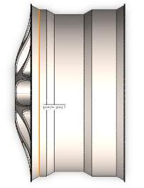
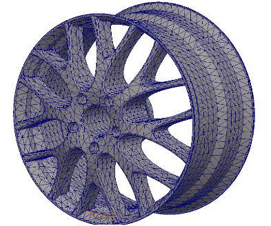
After Drilling the Rim, Different views of the product will be:
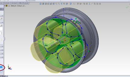
f) Bead Seat: Bead seat approaches in contact with the beadfaceanditisapartoftherimthatholdsthetireina radialdirection.
g) Hump: Itisabumpthatwasputonthebedseatforthe beadtopreventthe tirefromslidingofftherimwhilethe vehicleismoving.
h) Well: Thisisa partoftherim withdepthandwidthto facilitatetiremountingandremovalfromtherim.
5. STRUCTURAL ANALYSIS PROCEDURE
Theprocedureforastaticanalysisconsistsofthesetasks:
Buildthemodel
Setsolutioncontrol
Setadditionalsolutionoptions
Applytheloads
Solvetheanalysis
Canusebothlinearandnon-linearstructuralelements

Materialpropertiescanbelinearornon-linear,isotropic ororthotropic,andconstantortemperaturedependent.
Mustdefinestiffnessinsomeform(forexample,young’s modulus,hyperelasticcoefficients,andsoon).
For inertia loads (such as gravity), you must define the datarequiredformasscalculations,suchasdensity.
For thermal loads (temperatures), you must define the coefficientofthermalexpansion.
6.
OF MODEL
7. MATERIAL USED
Model
Thermal Expansion: 1.3e05/kelvin
SolidBody2 (Revolve 2) (wheel1), Solid Body 3(Fillet 35)(wheel1)
CurveData:N/A
Material Properties
Model Reference Properties Components
Name: 1060 Alloy
Model Type: Linear Elastic Isotropic
Default Failure: Max von mises
Stress
Yield
Strength: 2.75742e+07 N/m2
Tensile
Strength: 6.8935e+07 N/m2
Elastic modulus: 6.9e+10
SolidBody1 (CirPattern) (wheel 1), Solid Body 2(Revolve 2)(wheel1)
CurveData:N/A


8. ANALYSIS (RESULT
a.) Model Information
d.)
2) Aluminum Alloy
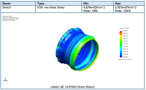
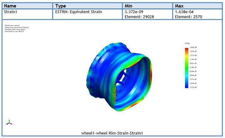
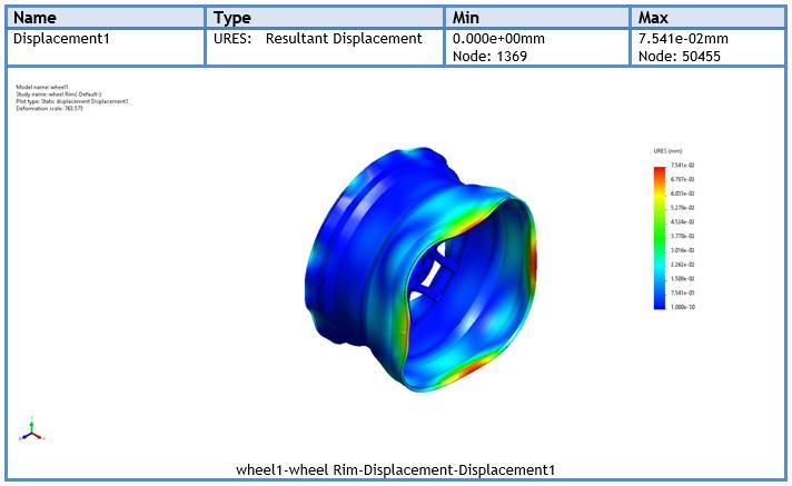
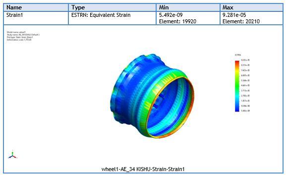
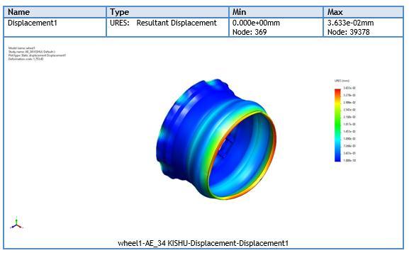
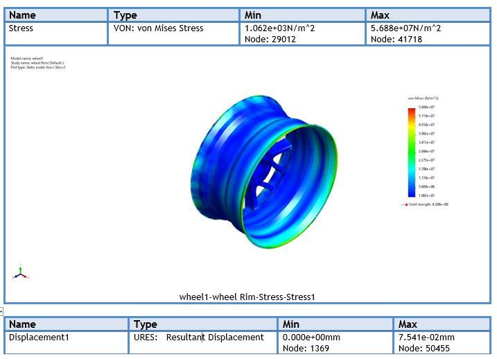
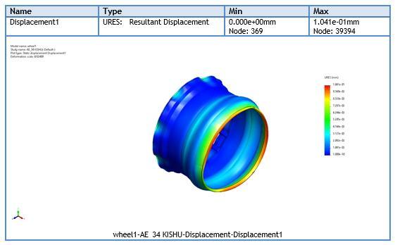
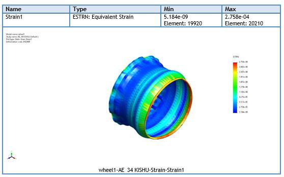
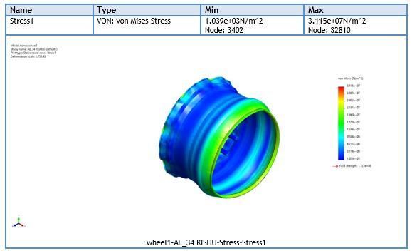
d.) Study Results
3. CONCLUSIONS
The number of cycles to failure in steel alloy is greater than in aluminum alloy, and stainless steel. As a result, steel alloy is more suitable for use in wheel rims than other materials. We can further optimize material thickness to reduce material consumption, and we can improve component life by using an advanced fatigue strainlifeapproach.
ACKNOWLEDGMENT
We would like to express our sincere thanks to Prof. A.K. Madan Sir, for his valuable guidance and support in completing our project. Sir provided us his valuable guidance throughout this project. We would also like to express our gratitude towards the university DELHI TECHNOLOGICAL UNIVERSITY for giving us this great opportunitytodoaprojecton“FEAANALYSISOFWHEEL RIM.”Withoutallthissupportthisprojectwouldnothave beencompleted.
REFERENCES
[1]. P. Meghashyam“Design and Analysis of Wheel Rim usingCATIA&ANSYS“Internationaljournalofapplication orinnovationinengineeringmanagement,Volume2,Issue 8,August2013.
[2]. LiangWang*-YufaChen–ChenzhiWang-Qingzheng Wang “the fatigue analysis of aluminum wheel rim”
Strojniški Vestnik – Journal of Mechanical Engineering 57(2011)1,31-39-June.2009.046.
[3]. International Engineering Research Journal of & Technology (IJERT)Vol. 3 Issue11, January –2014,ISSN: 2278-0181Modelingand Fatigue Analysis of Auto-motiveWheelRim.
[4]. Sunil N. Yadav, “Modelling and Analysis of Camber Angle on Fatigue Life of Wheel Rim of Passenger Car by Using Radial Journal Fatigue Testing “,s International of Engineering Science and Innovative Technology (IJESIT) Volume2,Issue 5,September2013.
[5]. International Journal of Engineering Research & Technology (IJERT) ISSN: 2278-0181, Volume 1 Issue, ISSN: 22778128, Stress Analysis Of Wheel Rim+7 Dr. Suwarna.
[6] Alexandru Valentin Radulescu –Sorin Cananau -Irina Radulescu et.al “Mechanical testing methods concerning thestressanalysisforavehiclewheelrim“olume2,33-39
[7] SunilN.Yadav,et.al“ModelingandAnalysisofCamber Angle on Fatigue Life of Wheel Rim of Passenger Car by Using Radial Fatigue Testing “, International Journal of Engineering Science and Innovative Technology (IJESIT) Volume2,Issue5,September2013
[8] P. Meghashyam- et.al “ Design and Analysis of Wheel Rim using CATIA & ANSYS “international journal of application or innovation in engineering management, Volume2,Issue8,August2013