International Research Journal of Engineering and Technology (IRJET)
e-ISSN: 2395-0056
Volume: 10 Issue: 04 | Apr 2023
p-ISSN: 2395-0072
www.irjet.net
Demonstration of Pascal’s law by using Hydraulic Jack Aditya Sonawane1, Vaibhav Belhekar2, Rahul Tandale3, M.C. Shete4 1,2,3,4Mechanical Engineering Department, Pune Vidyarthi Griha’s College of Engineering and Technology and G.K.
Pate (Wani) Institute of Management, Pune ---------------------------------------------------------------------***---------------------------------------------------------------------
Abstract - This research paper presents an experimental
The hydraulic jack used in this experiment has a maximum load capacity of 2 tons. It consists of a pump, a cylinder, and a piston. The pump is used to create pressure, which is transmitted to the cylinder. The piston is attached to the cylinder and moves up and down as pressure is applied. The piston is connected to a metal plate that is placed between the two steel plates.
demonstration of Pascal's Law using a hydraulic jack with a compression spring. The setup consists of two plates with a compression spring between them, two vertical bars, and a hydraulic jack mounted on the base plate. Pascal's Law states that pressure applied to a confined fluid is transmitted uniformly in all directions. In this experiment, we will apply force to the hydraulic jack, which will transmit the pressure equally to the two plates with the compression spring acting as a load cell. We will use pressure gauges to measure the pressure in the system and validate Pascal's Law. Additionally, we will perform a structural analysis of the supporting frame structure to ensure its safety and stability during the experiment.
Pressure gauges are attached to the hydraulic jack. The pressure gauges are used to measure the pressure in the system.
Key Words: Pascal’s Law, Hydraulic Jack, Fluid Mechanics, Demonstration
1.INTRODUCTION Pascal's Law is a fundamental principle of fluid mechanics. It states that pressure applied to a confined fluid is transmitted uniformly in all directions.[1] This law has numerous applications in engineering, particularly in the design and operation of hydraulic systems. A hydraulic jack is a common device that operates on the principles of Pascal's Law. In this experiment, we will demonstrate the application of Pascal's Law by using a hydraulic jack with a compression spring.
1.1 Experimental Setup: The experimental setup consists of two steel plates with a thickness of 20 mm each. The two plates are placed parallel to each other with 200 mm distance between them.
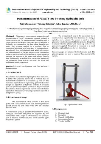
Fig.1 Experimental Setup
1.2 Components:
A compression spring is placed between the two plates, acting as a load cell. The plates are supported by two vertical bars with a height of 500 mm each. The hydraulic jack is mounted on the base plate and is used to apply force to the system.
© 2023, IRJET
|
Impact Factor value: 8.226
1. 2. 3. 4. 5.
|
Hydraulic Jack Base plate Upper & Middle Plate Compression Spring Two Vertical Bars
ISO 9001:2008 Certified Journal
|
Page 742