International Research Journal of Engineering and Technology (IRJET)
e-ISSN: 2395-0056
Volume: 10 Issue: 04 | Apr 2023
p-ISSN: 2395-0072
www.irjet.net
Hybrid Inverter Using Solar Battery Charger Priyanshu Dad, Swarup Maity , Varad Barbhai, Prof.Amit Kumar Patil 1Btech Student, Dept, Electronics & Communication Engineering, MIT ADT UNIVERSITY, Maharashtra, India 2Btech Student, Dept, Electronics & Communication Engineering, MIT ADT UNIVERSITY, Maharashtra, India 3Btech Student, Dept, Electronics & Communication Engineering, MIT ADT UNIVERSITY, Maharashtra, India
4 Assistant Professor, Dept, Electronics & Communication Engineering, MIT ADT UNIVERSITY , Maharashtra, India
---------------------------------------------------------------------***--------------------------------------------------------------------electricity from the grid, to generate power for domestic and Abstract - This report presents a study on the hybrid inverter
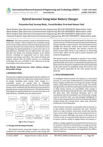
commercial use. The device consists of solar panels, batteries, charge controllers, and an inverter. The solar panels convert sunlight into electricity, which is then stored in batteries through the charge controller. The inverter converts the direct current (DC) stored in the batteries to alternating current (AC), which can be used to power domestic and commercial appliances.
using solar charger, which combines two renewable energy sources, solar energy and electricity from the grid, to generate power for domestic and commercial use. The hybrid inverter technology has gained popularity in recent years due to its high efficiency, reliability and cost effectiveness. The report describes the design and working principle of the hybrid inverter, including its components such as solar panels, batteries, and charge controllers. The results of testing and analysis indicate that the hybrid inverter is a promising technology that can contribute to the reduction of energy consumption and carbon emissions.
The hybrid inverter is designed to operate in two modes, namely, the grid-tied mode and the standalone mode. In the grid-tied mode, the inverter is connected to the grid and uses electricity from the grid to supplement the power generated by the solar panels. In standalone mode, the inverter uses only the power generated by the solar panels and the batteries.
Key Words: Hybrid, Inverter , Solar , Battery, charger, Renewable, Energy
1.INTRODUCTION
2. TITLE INFORMATION
The increase in global energy demand and the depletion of fossil fuels have led to the exploration of alternative sources of energy, including solar energy. Solar energy is a renewable source of energy that is abundant, environmentally friendly and cost-effective. The use of solar energy can be combined with the electricity from the grid to generate power using a hybrid inverter. The hybrid inverter technology has gained popularity in recent years due to its high efficiency, reliability and cost effectiveness.
An intelligent hybrid inverter, also known as a smart grid inverter, is a new type of dedicated U.P.S. (Uninterruptible Power Supply) system that can charge the system storage battery using both electrical and solar energy. The system storage battery can then be used to generate electricity if one or both energy sources are unavailable. Solar energy is typically only produced during the day, with midday being the peak time. This electricity fluctuates and is not coordinated with the household's use of electricity. Energy must be stored for later use and managed intelligently in order to close the gap between what is produced and what is needed during the evening hours when solar electricity production is not taking place. A DC-AC power converter is essentially what an inverter is. In the context of power electronics, the term "inverter" refers to a type of power conversion circuits that operate from a source of dc voltage or dc current and convert it to ac voltage or current. Although a dc source is the input to an inverter circuit, it is not unusual for this dc to come from an ac source, such as a utility ac supply. Hence, for instance, a
Fig-1: Block Diagram
utility ac voltage supply that is transformed to dc by an ac to dc converter and then inverted back to ac using an inverter could serve as the main source of input power. Hence, the output could have a frequency and magnitude that differs from the input ac.
1.1 Design And Working Principle The hybrid inverter using solar charger is a device that combines two renewable energy sources, solar energy and
© 2023, IRJET
|
Impact Factor value: 8.226
|
ISO 9001:2008 Certified Journal
|
Page 40