Simulation of Multiple Target Detection with Frequency Modulated
Continuous Wave Radar
Oğuzhan ÇAM1, Prof. İlyas ÇANKAYA2
1Student, Graduate School of Natural and Applied Sciences, Ankara Yıldırım Beyazıt University,Turkey

2Professor, Deparment of Electrical&Electronics Engineering, Ankara Yıldırım Beyazıt University, Turkey
Abstract - This study is about the FMCW Radar System Simulation for detecting multiple targets. The FMCW Radar system is a type of radar system that is capable of providing high range resolution and protection against electronic warfare techniques. It does this by emitting a frequency modulated chirp signal from a transmitting antenna, which allows the frequency of the signal to increase or decrease linearly over time. This modulation technique improves the range resolution of the radar system. Therefore, FMCW Radar system is widely used in military applications. The study aimed to improve the range resolution of the FMCW Radar system by optimizing the modules used in the system and processing the transmitted and received signals with advanced algorithms such as CA-CFAR and MUSIC. For evaluating the effectiveness of the system, the study created an environment with multiple targets and conducted a modeling and simulation study to determine the distances, velocities, and angular positions of the targets.
Key Words: Radar, Signal, FMCW Radar, Simulation, Detection
1.INTRODUCTION
A radar system is basically an electronic system used to propagateelectromagneticwavestransmittedthroughthe transmitting antenna when examined and to obtain information such as position, speed and distance of the objectbyusingasignalprocessingmethodbytakingthese electromagnetic waves from moving or immobile objects aftertheyarereflectedfrommovingorstationaryobjects. The word radar consists of the initials of the English words"RadioDetectingandRanging".Whenthestructure of a radar system is examined, it consists of transmitter, receiver and signal processor. Radar systems can be classified in different ways depending on their working principle, process, frequency, aim, application, structure, antenna, waveform, and installation area. FMCW Radar systems are typically classified under the structure classification, as they are characterized by their unique structure and components. FMCW Radar Systems consist basicallytransmitterantenna,receiverantenna,mixerand Radar Control Board. FMCW Radars generally are simple structure, cheap production cost , range detection capabilityandlessnoiseexposure.ThemajorityofPulsed Doppler radars are based on military battlefield radar technology and are typically used for wide area
surveillance. In contrast, FMCW Radar technology has been specifically designed and widely used in many different fields. These are level measurement, precision range measurement, hidden object detection, and target detection.In addition, FMCW Radar is also used in the automotive industry for short-range radars, such as anticollision warning and cruise control systems[1]. Continuous Wave(CW) radars use the Doppler effect to calculatethespeedofatarget,butnotitsdistance.FMCW Radars emerged to overcome this limitation by modulating and developing theCW waveform to generate a chirp signal, which can calculate both the range and speed of the target at the same time. A chirp signal is createdbymodulatingacontinuouswavewithasawtooth, triangular, or sinusoidal signal, which causes a frequency shift. This frequency shift can be used to determine the range and velocity of the target[2]. So when FMCW Radar compare to other radars[3], FMCW Radars are one step aheadofpulseradars.Inaddition,thedisadvantageofCW radars not being able to detect multiple targets is eliminated with FMCW Radar [4]. FMCW Radars have the detection to multiple targets based on FMCW Radar in rangeresolution.
In this study, the aim is Ambiguity Multiple Target Detection with Frequency Modulated Continuous Radar System.AmbiguityMultipleTargetDetectioncanbecalled a technique. The technique is based on the principle of range-Doppler ambiguity, which states that the range and Doppler frequency of a target cannot be uniquely determinedfromasingleradarmeasurement.
This is due to the fact that the range and Doppler frequency are related by the radar's sweep rate and carrier frequency. One of the main advantages of Ambiguity Multiple Target Detection is that it allows for the detection of multiple targets in a single radar measurement[5]. This is particularly useful in situations where multiple targets are present in close proximity to each other, such as in crowded airspace or in battlefield scenarios. The implementation of Ambiguity Multiple Target Detection in a FMCW Radar system requires advanced signal processing techniques, such as pulse compression, matched filtering, CFAR, MUSIC and FFT. These techniques are used to improve the signal-to-noise ratio of the received signal, which in turn improves the accuracy and resolution of the target detection. FMCW
Radarissimulatedinanenvironmentwherethereismore than one target, and targets are detected by using FFT, CFARandMUSICalgorithmsinthisstudy.
Fast Foruier Transform(FFT) algorithm is widely used to common for extracting range and Doppler information from the received signals. The signal processing chain in FMCW Radar involves transmitting a frequencymodulatedsignalandreceivingthereflectedsignal,which is mixed with the transmitted signal to produce a beat signal. The beat signal is then sampled and processed using FFT to obtain the range and Doppler information. TheFFTisacomputationallyefficientmethodforspectral analysisandcanquicklytransformtime-domain data into frequency-domain data. The Range-Doppler map can be generated by using FFT. It can be shown the range and velocity information of detected targets. This information is then used to identify and track moving targets, while stationaryobjectscanbeeliminatedusingclutterremoval algorithms. Despite its computational complexity, FFT is an essential tool for FMCW Radar signal processing and plays a critical role in achieving accurate and reliable targetdetectionandtracking[6].
The Cell Averaging Constant False Alarm Rate (CA-CFAR) algorithm is widely used in FMCW radar systems to maintain robust detection performance in complex environments with high levels of background noise and clutter.Thealgorithmisbasedontheprincipleofsettinga detection threshold based on the predicted background level, which is calculated as the weighted average of clutter data in the reference window. This predicted background level is commonly referred to as the mean level. The CA-CFAR algorithm dynamically adjusts the detection threshold based on the local clutter level, reducing the likelihood of false alarms caused by variationsinthebackgroundlevel[7].
Multiple Signal Classification (MUSIC) is a high-resolution spectral estimation algorithm that can be used in FMCW Radarsystemstoimprovetargetdetectionandtrackingin the presence of multiple interfering sources. The algorithmisbasedontheeigenvaluedecompositionofthe received signal's covariance matrix and estimates the direction of arrival (DOA) of the target signals. The DOA information can then be used to estimate the range and velocityofthetargets.TheMUSICalgorithmcanprovidea significant advantage over traditional FFT-based methods in scenarios where the number of targets is greater than thenumberofsensorsorwhentargetshavesimilarrange andDopplercharacteristics.Thealgorithmisalsoeffective inreducingtheeffectsofinterferencefromstationaryand moving clutter sources, improving target detection and tracking accuracy. However, the MUSIC algorithm can be computationally demanding and requires more complex hardware than FFT-based approaches[8,9]. Nevertheless, its high-resolution capabilities make it a valuable tool for
improving the performance of FMCW Radar systems in complexenvironments.
In the next parts of the study, the examination of the featuresoftheFMCWRadarSystem,theexaminationofits general structure, the stages of the simulation carried out in the MATLAB software for ambiguity multiple target detectionwerementioned,andfinallytheresultsobtained were evaluated and an idea was given about what the futureworkscouldbe.
2. AMBIGUITY MULTIPLE TARGET DETECTION WITH FMCW RADAR
2.1 Ssytem Information
FMCWRadarsaredefinedasFMCWRadarsthathavebeen developed by applying Frequency Modulation or Numerical Modulation techniques to Continuous Wave(CW) radars. Frequency Modulated Continuous Wave (FMCW) radar is a type of radar that uses a continuous transmission of electromagnetic waves at a specific frequency, which is then modulated over time. The frequency of the transmitted wave is continuously variedoveraperiodoftime,andtheresultingfrequencyof the reflected wave is then analyzed to determine the range,velocity,andothercharacteristicsofatarget.
The basic principle of FMCW Radar is based on the conceptoffrequencyshift.Whenanelectromagneticwave is reflected off of an object, the frequency of the reflected wave will be shifted by an amount proportional to the distanceoftheobjectfrom theradar.This frequencyshift is known as the Doppler shift. By analyzing the frequency shift of the reflected wave, the range and velocity of the objectcanbedetermined.
FMCWRadarsystemstypicallyuseafrequencymodulated waveform,inwhichthefrequencyofthetransmittedwave is linearly swept over a specific range. The frequency modulatedwaveformhasseveralbenefits,includingahigh range resolution and a low probability of intercept (POI) byanenemyradarsystem.
OneofthemainadvantagesofFMCWRadarisitsabilityto determine the range of an object with high accuracy. This is due to the linear nature of the frequency sweep, which allows for a high range resolution. Additionally, FMCW Radar is able to detect small and slow-moving objects, making it ideal for applications such as automotive radar andindustrialprocesscontrol.
FMCW Radar is also commonly used in military applications, such as air defense and surveillance. The radar'sabilitytodetectsmall andslow-movingtargets, as well asitslowPOI,makesit well-suitedforthesetypesof applications.
2.2 Ssytem Overview
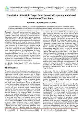
FMCW Radar system is composed of a transmitter, receiver, modulator, demodulator, and antenna as shown Figure1.Thetransmittergeneratesacontinuouswaveata specific frequency, which is then modulated by the modulator, creating a frequency modulated waveform. The frequency modulated waveform is then transmitted by the antenna and the reflected wave is received by the antenna and sent to the receiver, demodulator and analyzedtodeterminetherangeandvelocityoftheobject.
FMCWRadarSystemshavesameconcenpt,andworkwith using same principle that is Frequency Modulation. The Signal of FMCW Radar can be four different modulated signals . These are Triangular, Sinusodial, Square and Sawtooth. Also these signal types can offer in signal processing.
Signal Processor: This component performs various signal processing functions on the IF signal, such as filtering, amplification, and demodulation. The signal processor also extracts range and velocity information fromtheIFsignal.
Display: This component presents the radar data to the operatorinameaningfulway,suchasonaradarscopeor map.
Control Unit : Thiscomponentcontroltheoverallsystem, it contains all the parameters of the radar system and it communicatewiththesignalprocessingunit.
2.2 The Usage Areas of FMCW Radar
FMCW Radar system is a type of radar technology that is widely used in a variety of applications due to high accuracy and ability to provide real-time data. FMCW Radar system operates by emitting a continuous wave signal that varies in frequency over time, and then analyzing the reflected signal to determine the distance, velocity, and other characteristics of the target. This technology can be used for a wide range of applications, including level measurement, vehicle collision avoidance, precision range measurement, hidden object detection, andmore.Inthisway,FMCWRadarsystemhasbecomean important role in many fields, from aviation and marine navigationtoenvironmentalmonitoringandconstruction.
2.2.1 Radio Altimeter
The System Block Diagram of FMCW Radar is typically includesthefollowingcomponents:
Transmitter: Thiscomponentgeneratesandamplifiesthe radiofrequency(RF)signalthatwillbetransmittedbythe antenna. The signal is typically a continuous waveform thatisfrequencymodulatedtoproviderangeinformation.
Transmit/Receive (T/R) Switch: Thiscomponentdirects theRFsignalfromthetransmittertothetransmitantenna and receives the reflected signals from the target via the receiveantenna.
Antennas: ThesecomponentstransmitandreceivetheRF signals.Thetransmitandreceiveantennascanbeseparate orcombinedintoasingleelement.
Mixer: This component combines the transmitted and received signals, creating an intermediate frequency (IF) signal.
Local Oscillator (LO): This component generates a referencefrequencythatismixedwiththereceivedsignal inthemixer.
A radio altimeter is a type of radar that is specifically designed to measure the altitude of an aircraft above the ground. FMCW Radar is a type of radar that uses frequency modulation to transmit and receive signals. In an FMCW Radar, the transmitted signal is modulated in frequency, and the received signal is compared with the transmittedsignaltodeterminetherangetothetarget.
In a radio altimeter that uses FMCW Radar, the radar transmits a frequency-modulated continuous wave signal towardstheground.Thesignalreflectsoffthegroundand returns to the radar. By comparing the frequency of the reflected signal with the frequency of the transmitted signal, the radar can determine the range to the ground. Thisrangemeasurementisusedtodeterminethealtitude oftheaircraftabovethegroundasshowninFigure2.
RadioaltimetersusingFMCWRadararecommonlyusedin commercial and military aircraft for landing and takeoff operations. They are particularly useful in situations wheretheaircraftisoperatinginlowvisibilityconditions, such as during fog, rain, or snow. By providing accurate altitude information, they help pilots to maintain a safe altitudeduringcriticalphasesofflight,suchastakeoffand landing.
2.2.2 Proximity Fuse
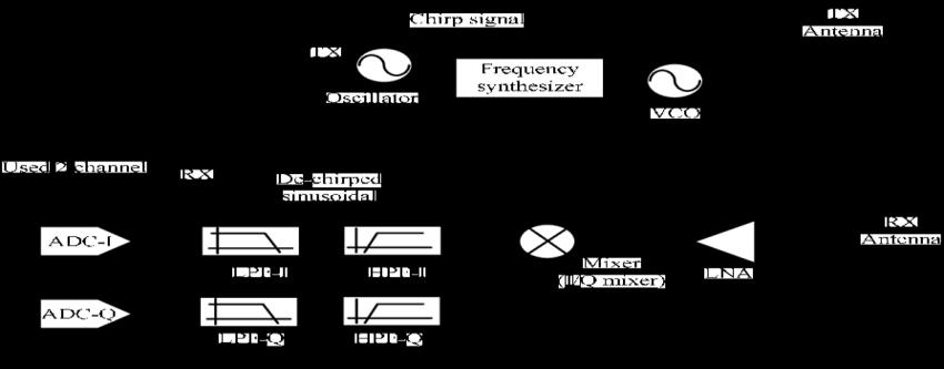
Aproximityfuseisa typeof electronicdevicethatisused in munitions, such as bombs and missiles, to detonate them when they are close to their intended target. In FMCW Radar, a proximity fuse can be implemented by using the radar to measure the distance between the munitionanditstarget.
InanFMCWRadarproximityfusesystem,theradaremits a continuous wave signal towards the target. The signal reflects off the target and returns to the radar. By comparing the frequency of the reflected signal with the frequency of the transmitted signal, the radar can determinetherangetothetarget.
The proximity fuse system uses this range information to determinewhenthemunitioniscloseenoughtothetarget todetonate.Oncethemunitionreachesthepredetermined distancefromthetarget,theproximityfusesendsasignal todetonatethemunition.
FMCW Radar is particularly well-suited for use in proximity fuse systems because it provides very accurate range information. This accuracy is essential in proximity fuse systems because even small errors in range measurementcancausethemunitiontodetonatetooearly ortoolate,whichcanreduceitseffectiveness.
ProximityfusesusingFMCWRadararecommonlyusedin military munitions, such as air-to-air missiles and antiship missiles. They allow these munitions to be more effective by increasing their accuracy and reducing the risk of collateral damage An example proximity fuse by manufacturedasshowninFigure3
2.2.3 Level Measuring Radar
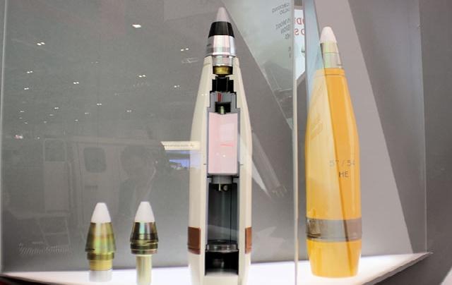
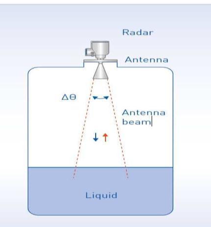
Level measuring radar is a type of radar that is used to measure the level of liquid or solid materials in tanks or containers. FMCW Radar technology can be used to implement level measuring radar systems as shown in Figure4

In an FMCW Radar level measuring system, the radar emits a continuous wave signal towards the material in thetank.Thesignal reflectsoffthesurfaceofthematerial and returns to the radar. By comparing the frequency of the reflected signal with the frequency of the transmitted signal,theradarcandeterminetherangetothesurfaceof thematerial.
Thelevelofthematerialinthetankcanbedeterminedby subtracting the distance between the radar and the surface of the material from the height of the tank. The radar can continuously measure the level of the material inthetankandprovidereal-timedatatoacontrolsystem.
FMCW Radar level measuring systems are widely used in industrial applications, such as oil and gas production, chemical processing, and wastewater treatment. They are highly accurate and reliable, even in harsh environments, and can be used to measure the level of a wide range of materials, including liquids, powders, and granular materials.
In addition to level measurement, FMCW Radar level measuring systems can also be used to monitor the volume, flow rate, and density of materials in tanks and containers.Theyareanimportanttoolforprocesscontrol andcanhelptooptimizeproductionandreducecosts.
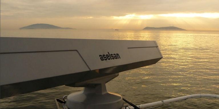
2.2.4 Naval Navigational Radar
Naval navigational radar isa type of radar that is used by naval vessels to detect and track other vessels, obstacles, and land masses. FMCW Radar technology can be used to implement naval navigational radar systems as shown in Figure5.
In an FMCW Radar naval navigational system, the radar emits a continuous wave signal towards the surrounding environment.Thesignalreflectsoffanyobjectsinitspath and returns to the radar. By comparing the frequency of the reflected signal with the frequency of the transmitted signal,theradarcandeterminetherangetotheobject.
Naval navigational radar can be used to detect other vessels,includingsurfaceshipsandsubmarines,aswellas obstaclessuchasicebergs,reefs,andshorelines.Itcanalso be used to provide information on the location and movement of land masses, which is important for navigationandavoidinghazards.
FMCW Radar naval navigational systems are highly accurate and can provide real-time data to a ship's navigation system. They are essential for safe navigation in all weather conditions, including low visibility conditionssuchasfogandheavyrain.
Inaddition to navigation,FMCWRadar naval navigational systems can also be used for surveillance and reconnaissance. They can detect and track other vessels and aircraft, providing early warning of potential threats andallowingtheship'screwtotakeappropriateaction.
Overall, FMCW Radar naval navigational systems are an important tool for naval vessels, providing essential informationforsafenavigationandeffectivesurveillance.
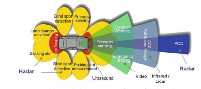
2.2.5 Vehicle Collision Avoidance
Vehicle collision avoidance radar is a type of radar that is used in vehicles, such as cars, trucks, and buses, to detect and avoid collisions with other vehicles or obstacles. FMCWRadartechnologycanbeusedtoimplementvehicle collisionavoidanceradarsystemsasshowninFigure6.
InanFMCWRadarvehiclecollisionavoidancesystem,the radar emits a continuous wave signal towards the surrounding environment. The signal reflects off any objectsin its pathand returnsto the radar.By comparing thefrequencyofthereflectedsignalwiththefrequencyof the transmitted signal, the radar can determine the range totheobject.
Vehicle collision avoidance radar can be used to detect other vehicles, as well as pedestrians, cyclists, and other obstacles. It can provide information on the range, speed, and direction of these objects, allowing the vehicle's control system to take appropriate action to avoid a collision.
FMCW Radar vehicle collision avoidance systems are highly accurate and can provide real-time data to a vehicle's control system. They are essential for improving the safety of vehicles, particularly in urban environments wheretherearehighdensitiesofvehiclesandpedestrians.
In addition to collision avoidance, FMCW Radar vehicle collision avoidance systems can also be used for adaptive cruisecontrolandlanedeparturewarningsystems.These systems use the radar to maintain a safe distance from othervehiclesandtoprovidewarningswhenthevehicleis driftingoutofitslane.
Overall, FMCW Radar vehicle collision avoidance systems are an important tool for improving the safety of vehicles and reducing the risk of accidents. They are increasingly being adopted by car manufacturers as a standard safety feature.
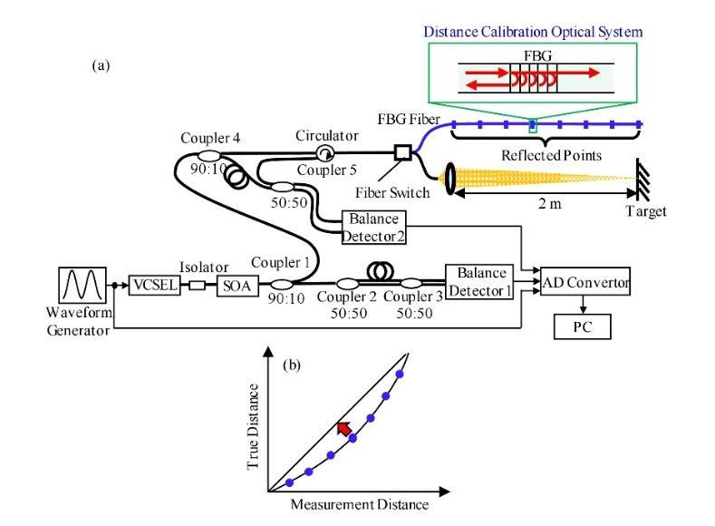
2.2.6 Precision Range Meter for Fixed Targets
A precision range meter is a type of radar that is used to measure the range to fixed targets, such as buildings or landmarks. FMCW Radar technology can be used to implementprecisionrangemetersystems.
In an FMCW Radar precision range meter system, the radar emits a continuous wave signal towards the target. The signal reflects off the target and returns to the radar. By comparing the frequency of the reflected signal with the frequency of the transmitted signal, the radar can determinetherangetothetarget.
FMCW Radar precision range meters are highly accurate and can provide precise range measurements with a resolution of a few centimeters. They are often used in applications where accurate range information is required,suchasinsurveying,mapping,andconstruction.
Inadditiontorangemeasurement,FMCWRadarprecision range meters can also be used to provide information on thelocationandsizeofthetarget.Thisinformationcanbe usedfordetailedmappingand3Dmodelingofthetarget.
Overall, FMCW Radar precision range meters are an important tool for a range of applications where accurate range measurements are required. They are highly accurate and can provide real-time data to a control system.Theexperimantalsetupforprecisionrangemeter withFMCWRadarsystemisshownasFigure7.
2.2.6 Measurement of Very Small Motions
FMCW Radar technology can be used to measure very small motions with high precision. An example of measuring small movements is monitoring the vibrations of different parts in machines. A device is needed that is nophysicalcontactwiththevibratingcomponentforsuch measurement. This can be achieved using a technique called interferometry, which is based on the interference betweentwoormoreradarsignals.
Inaninterferometry-basedFMCWRadarsystem,theradar emits two or more signals with slightly different frequencies towards the target. The signals reflect off the target and return to the radar, where they are compared to each other. The difference in the frequency of the reflected signals is proportional to the distance travelled bythetargetduringtheemissionofthesignals.
By comparing the frequency difference of thereflected signals at different times, the radar can determine the motion of the target. This is because any motion of the target during the emission of the signals will cause a changeinthefrequencydifferenceofthereflectedsignals.
Interferometry-basedFMCWRadarsystemscanbeusedto measure very small motions, such as vibrations or deformations of structures, with high precision. This is because they can detect changes in the frequency differenceofthereflectedsignalsthatareassmallasafew millihertz.
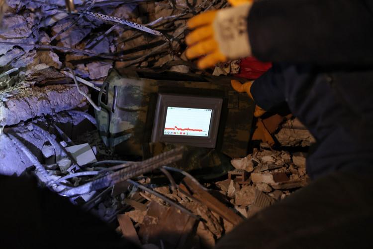
Overall, interferometry-based FMCW Radar systems are an important tool for measuring very small motions with high precision. They are increasingly being used in applications such as structural health monitoring as shown in Figure 8, where they can provide valuable
information on the condition of infrastructure and other structures.
Overall, FMCW Radar technology is an important tool for hidden object detection. It allows for the detection of objects that are not visible to the naked eye and can providevaluable informationfora variety ofapplications. In the earthquake disaster in Kahramanmaraş, The imagingwasprovidedfromunderthedebriswiththeDAR RadarproducedbySTMasshowninFigure9.
2.2.8 Hidden Object Detection
FMCWRadartechnologycanbeusedfordetectinghidden objects that are not visible to the naked eye. This can be achieved by analyzing the radar signals reflected off the objectsandidentifyingpatternsthatindicatethepresence ofhiddenobjects.
In a hidden object detection FMCW Radar system, the radar emits a continuous wave signal towards the surrounding environment. The signal reflects off any objects in its path and returns to the radar. The reflected signalsarethenanalyzedtoidentifypatternsthatindicate thepresenceofhiddenobjects.
Oneofthekeytechniquesusedforhiddenobjectdetection issyntheticapertureradar(SAR).SARisamethodofusing radarsignalstogeneratehigh-resolutionimagesofobjects thatarenotvisibletothenakedeye.Itworksbyemittinga series of radar signals from different positions and combiningthereflectedsignalstogenerateanimageofthe object.
Another technique used for hidden object detection is ground-penetrating radar (GPR). GPR is a type of radar thatisusedtoimageobjectsbeneaththeground.Itworks by emitting a radar signal into the ground and measuring thereflectionsfromsubsurfaceobjects.
HiddenobjectdetectionFMCWRadarsystemsareusedin a variety of applications, including security, search and rescue, and archaeological surveys. They can detect objects that are hidden from view, such as buried objects, hiddencompartments,andconcealedweapons.
3. FREQUENCY MODULATION TYPES OF FMCW RADAR
Modulation is applied to the transmitter signal to enable themeasurementofrangeandvelocityoftargetsinFMCW Radar systems.The type of modulation used depends on thecriticaldatathatneedstobeobtained,andthedesired range-speed resolution. These modulation types are sawtooth,triangleandsinusodialwavemodulation.
The sawtooth wave modulation is used in radar systems where range measurement is critical. The sawtooth wave allows for high range resolution since it has a linearly increasingfrequency.
The triangle wave modulation is used in radar systems where both range and velocity information are critical. Thisisbecausethelinearrampofthetrianglewaveallows for accurate measurement of range, while the frequency modulationenablesthemeasurementofvelocity.
The sinusoidal wave modulation is used in radar systems where velocity measurement is critical. By measuring the Doppler shift of the reflected signal, the velocity of the targetcanbecalculated.
It is important to note that the modulation type to be applied may vary according to the bandwidth and modulation time depending on the desired range-speed resolution. In general, the higher the bandwidth and modulationtime,thebettertherange-speedresolution.
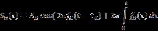
The general equations related to Frequency Modulation and according to wave types are given below. The frequencymodulationintransmittedsignalisdefinedthat usedgenerallyas
(1)
where fc is carrier frequency and is the signal that the carrier frequecy. The maximum or minimum difference between the modulated signal and the carrier frequency is . This equation demonstrates the transmitted frequency; the received frequency is delayed by ), with and doppler shift by ,whereTistheperiodofthemodulatedsignal.
3.1 The Sawtooth Wave Modulation
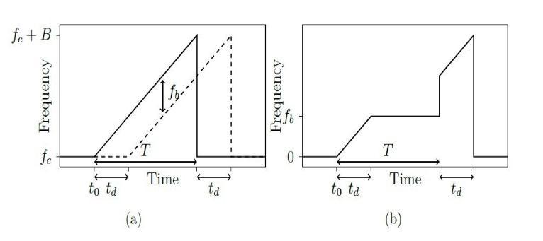
A sawtooth wave modulation is a type of frequency modulation used in radar systems. In this modulation technique, the frequency of the transmitted signal is varied in a linear ramp over time, creating a sawtooth waveform.An exampleofSawtooh Waveformisshown as Figure 10. The sawtooth modulation is typically used in radarsystemswhererangemeasurementiscritical.When the transmitted signal reflects off a target, the received signalisshiftedinfrequencyduetotheDopplereffect.The sawtooth modulationallows for accurate measurement of the Doppler shift, which can be used to determine the targetvelocity.Thelinearrampofthesawtoothwaveform also provides a high range resolution since it provides a linearlyincreasingfrequency.Thegeneralequationsabout thesawtoothwavemodulationaregivenbelow. (2) (3)
(6)
The expression being referred to in the above equation both time-dependent and non-time-dependent terms, which can be observed in the Fourier transform of the signal. The time-dependent terms include those that are proportionalto ,andtheireffectsarevisibleinthephase of the Fourier transform. The terms that are proportional totcanbeobservedinthe spectrumofthesignal.Two of the time-dependent terms are considered negligible, and thefrequencypeakcanbeexpressedaswithbothdoppler andrangevalue
(7)
(4)
(5)
Where is the frequency of transmitted frequency, is the frequency of received signal, is the transmitted signaland isthereceivedsignal.
The transmitted and received signals are mixed by multiplying in the time domain. The mixed signal can be expressedas
3.2 The Triangle Wave Modulation
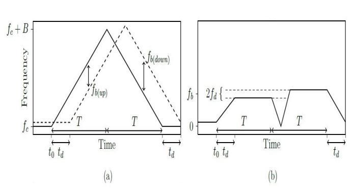
A triangle wave modulation is a type of frequency modulation used in radar systems. In this modulation technique, the frequency of the transmitted signal is varied in a linear ramp over time, creating a triangular waveform. An example of Triangular Waveform is shown as Figure 11. The triangular modulation is typically used in radar systems where both range and velocity informationarecritical.
When the transmitted signal reflects off a target, the received signal is shifted in frequency due to the Doppler effect. The triangular modulation allows for accurate measurement of the Doppler shift, which can be used to determine the target velocity. The linear ramp of the triangular waveform also enables accurate measurement of the time delay between the transmitted and received signals, which can be used to calculate the range of the target
The triangular wave modulation analysis is similar to the sawtoothwavemodulation,sincethesignalfor0<t<T/2 is like a sawtooth signal with half the period, and the signalforT/2<t<Tisthenegativeofthesignalfor0<t< T/2.
(8) (9)
Thefrequencyequationsforuprampanddownrampcan beexpressedaswhenthetransmittedandreceivedsignals aremixed (12) (13)
When the spectrum of mixed signal is analyzed, two frequency terms can be observed. By utilizing these frequencies,itispossibletocalculatethevaluesofvelocity andrange
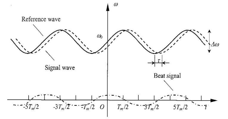
Waveform is shown as Figure 12. The sinusoidal modulation is typically used in radar systems where the measurementoftargetvelocityiscritical.
When the transmitted signal reflects off a moving target, the frequency of the reflected signal is shifted due to the Doppler effect. By measuring this frequency shift, the velocity of the target can be calculated. The sinusoidal modulation allows for accurate measurement of the Doppler shift and thus enables the determination of the targetvelocity.
The general equations about the sinusodial wave modulationaregivenbelow.
(14)
(15)
Once modulation is applied, the signals are expressed using complex exponential terms as shown below, where isaphasethatcantakeon arbitraryphasevalue.
(16)
(17)
By using exponential notation, the mixed signal can be expanded and then subjected to low pass filtering, which producesthefollowingequation
3.3 The Sinusodial Wave Modulation
A sinusoidal wave modulation is a type of frequency modulation used in radar systems. In this modulation technique, the frequency of the transmitted signal is varied sinusoidally over time. An example of Sinusodial
Although the spectrum of the signal may contain multiple frequency peaks, only a few of them are relevant. Specifically, the center frequency located at the Doppler frequency , and the upper and lower sidebands. The phasesofthesesidebandsaredifferentfromthedominant frequency by a factor of , where , isthemodulationfrequency,R isthedistanceofthetarget,andcisthespeedoflight.
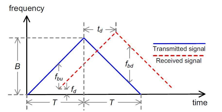
Gradually Changing Waveform is a method used to improvetherangeresolutionof radarsystemsusingpulse compressiontechniques.Thismethodismadepossibleby the adjustable bandwidth feature of frequency modulated radars, which allows for the range resolution to be improvedwithinacertainfrequencyrange.Thetechnique involves dividing the transmitter signal into sub-pulses with smaller bandwidths within an adjustable frequency band as shown in Figure 13. This allows for the received echo signal to be accurately assigned to each carrier frequency, resulting in an effective greater wider bandwidth and improved range resolution. Additionally, thistechniqueimprovesreceiverimmunitytointerference and minimizes mutual interference with other radars operating in the same frequency band. The mathematical equations applied in transmitted, received and mixed signalsofFMCWRadararespecified.
is a continuous wave with a frequency that increases linearlywithtime.Theequationforthetransmittedsignal is shown in equation (19). The frequency of received signalisshowninequation(20)whichisalinearfunction of time and is affected by the Doppler shift caused by the motion of the reflecting object. The time delay td is also accounted for in equation (20). The received signal is shown in equation (21) which is the echo of the transmitted signal after it has been reflected off of the object. This signal is affected by the time delay and the Doppler shift, as represented by equation (20). Trasnmitted signal ST(t) and received signal SR(t) are mixed by multiplication for obtaining doppler frequency and beat frequency. The intermediate frequency (IF) signal SIF(t)isshowninequation(22)fortheuprampand in equation (23) for down ramp. The beat frequency equations are shown in equations (24) and (25) for up anddown.Thetargetrange R andtheradialvelocity V are showninequations(26)and(27).
In summary, FMCW Radar systems use a frequencymodulated continuous wave signal to measure the distance and velocity of an object. The transmitted signal is a continuous wave with a frequency that increases linearlywithtime, whilethe receivedsignal isthe echo of thetransmittedsignalafterithasbeenreflectedoffofthe object.Bymeasuringthefrequencydifferencebetweenthe transmittedandreceivedsignals,thedistanceandvelocity oftheobjectcanbedetermined.
The transmitted signal of an FMCW Radar System can be expressedas
(19)
where , is transmit frequency as a linear function of time, fc is carrier frequency, B is the bandwith, AT is amplitude of transmitted signal , T is the timeperiodofsignal.Thefrequencyofreceivedsignalcan beexpressedas
(20)
FMCW (Frequency Modulated Continuous Wave) radar systems are used to measure the distance to an object by transmitting a continuous wave signal that is frequencymodulatedwithalinearramp.Thissignalisknownasthe "chirp" signal, and it is used to determine the range of an object by measuring the time delay between the transmitted and received signals. The transmitted signal
Where , , td is time delay due to reflectedsignal,fD :isdopplershift,R0 istherRangeatt=0, v is the velocity of target, c is the speed of light. The receivedsignalcandeexpressedas
(21)
whereAR istheamplitudeofreceivedsignal.
ST(t) and SR(t) are mixed by multiplication for obtaining doppler frequency and beat frequency. The intermediate frequency (IF) signal SIF(t) can be obtained for the up rampas
(22)
Similarly,theIFsignal SIF(t)canbeobtainedforthedown rampas
(23)
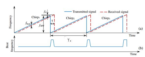
Consequently, The beat frequency equations for up and downcanasshowninFigure14andbeexpressedas
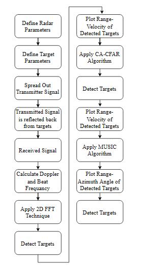
1. Itdefinestheparametersoftheradarsystemasshown in Table 1, such as the speed of light, bandwidth, carrier frequency, number of ADC samples, number of chirpsperframe,pulserepetitioninterval,andothers.
2. It defines the two target according to informations in Table2.Itsimulatesthemovementoftwotargetsover time by calculating their locations at each point in the time axis. It sets up some variables such as range and velocityaxis,andangleaxis.
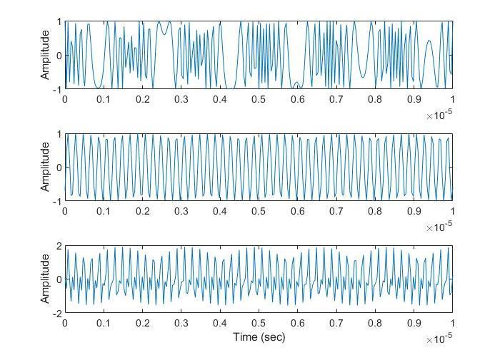
3. ItsimulatesTransmittedSignal
4. ItsimulatesReceivedSignal
5. ItsimulatesMixSignal with TransmittedandReceived Signal
6. ItsimulatesFFTOperations
7. ApplyCA-CFARAlgorithmfordetectingmultipletarget
8. AppyMUSICAlgorithmfordetectingmultipletarget
5. MATLAB SIMULATION
The FMCW Radar Simulation for detecting Ambuguity Multiple Target on Matlab is follows steps and explains withflowchartinFigure15:
5.1
Some processing is performed before generating the transmitter signal on MATLAB Simulation Code. These processing is a part of a MATLAB simulation that calculates the time delays between targets and transmitter-receiver pairs in a 3D space. It creates arrays of transmitter and receiver locations and target locations over time, and uses the Euclidean distance formula to calculate the delays, which are stored in cell arrays. After these processes, the transmitter signal is generated according to the radar signal parameters that specified in ParametersofFMCWRadarasshowninFigure16.
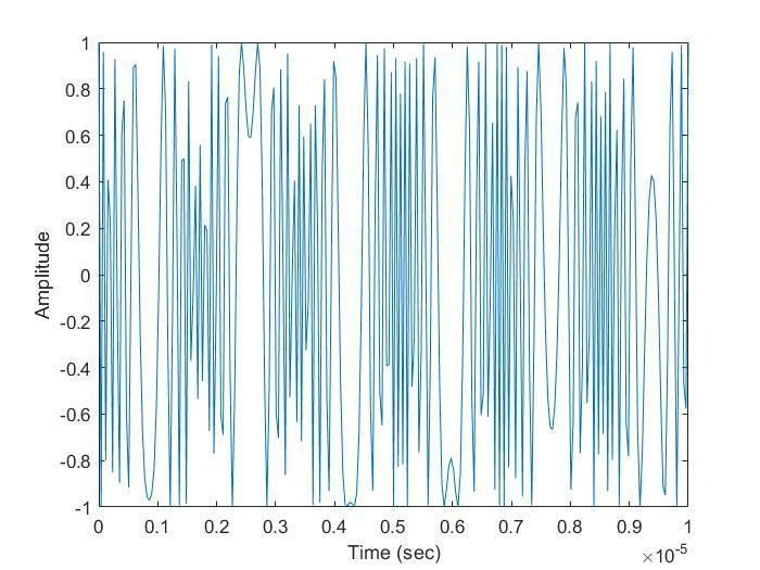
5.2 Mixed Signal
This part generates a mixed signal and plot the mixed signal as shown in Figure 17 by mixing the two target signalswiththetransmitted signal inMATLABSimulation Code . It uses specific functions to calculate the phase of the transmitted and received signals, and defined rangedependent and doppler-dependent frequency and intermediate frequency for the two targets. It uses a nestedforlooptoiterateoverall thetransmitter-receiver pairs,andwithinthat,overallthechirpsandpulsesinthe data. It calculates the phase of the transmitted signal, the phaseofthereceivedsignalsfromthetwotargetsandthe differenceinphase between the transmittedand received signals, uses the exp() function with the calculated phase to generate the time-domain signal and adds the two targetsignals.Theresultingmixedsignalisthenstored in acellarraycalled"mixed"
5.3 FFT Operations
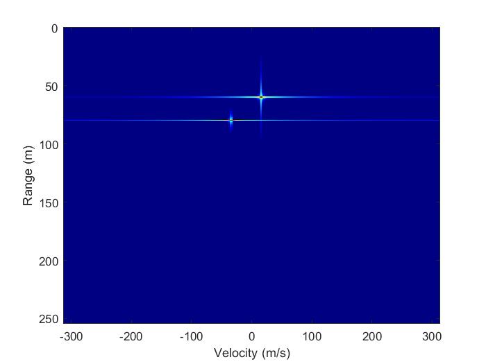
The FFT part of code reshapes the mixed signal data and appliesa 2DFouriertransformto createa Range-Doppler Map (RDM). It reshapes the mixed signal data into a 3D array called "RDC" and applies a 2D FFT on it using "fft2" and "fftshift" functions to create a 4D array called "RDM" with dimensions of number of ADC, number of Chirps, multiplying the number of receiver and transmitter antennas,numberofCPIandplotstheRange-DopplerMap usingthe"imagesc"functionasshowninFigure18.Italso applies a colormap, sets the color axis limits and adds x andylabels.
5.4 CA-CFAR Algorithm
This part of code applies a Constant False Alarm Rate (CFAR) detection algorithm to a Range-Doppler Map (RDM) in order to identify target returns as shown in Figure19.TheCFARalgorithmcomparesthepowerofthe target return to the power of the surrounding noise and decidesifthetargetreturnisreal.Itdefinesthenumberof guardcells andtrainingcells andthedesiredfalsealarm rate andalsodefinesanSNRoffsetvalue indB.TheRDM data is passed in dB scale. It calls the “ca_cfar” function which takes in RDM data, number of guard cells, number oftrainingcells,desiredfalsealarmrate,andSNRoffsetas inputs, and returns the range-Doppler map with a CFAR mask applied to it, CFAR detected ranges, CFAR detected Doppler values and the threshold value. The CFAR algorithm used here is Cell Averaging CFAR (CA-CFAR) which compares the power of the target return to the averagepowerofthesurroundingnoise.
5.5 MUSIC Algorithm
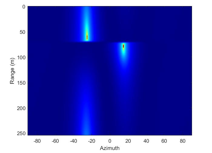
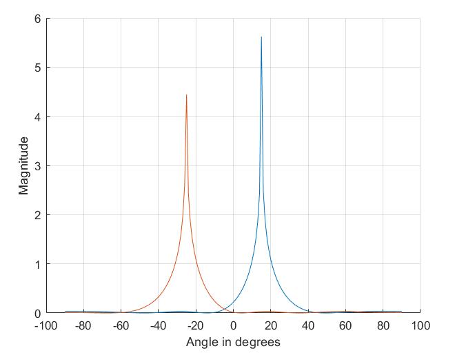
ThispartofcodeappliestheMultiple Signal Classification (MUSIC)algorithmtotheRDCdatatoestimatetheangleof arrival (AoA) of the targets. MUSIC is a subspace-based technique that is used to estimate the AoA of multiple signals in a noisy Environment. It applies 1D FFT on the RDC along the range dimension and uses a for loop to iterate over all range bins, creating the matrix by summing the outer product of the signal vector for each snapshot and divide it by the number of snapshots and plot "MUSIC Sprectrum" as shown in Figure 20. It then applies the MUSIC algorithm to the created matrix using the estimator object and obtains the DOA estimates. It creates a new figure and plots the range-angle map using the "imagesc" function with the angle values and range values.Italsoappliesacolormap,setsthecoloraxislimits andplot "MUSICRange-AngleMap"asshowninFigure21.
5. CONCLUSION
Some signal processing algorithms were applied in the simulation study for the detection of ambiguity multiple targets with FMCW Radar in Matlab software. These are FFT, CA-CFAR and MUSIC algorithms. The Range and Velocity information of the targets were determined by the CA-CFAR algorithm. Azimuth angles of the targets were successfully determined with the applying MUSIC algorithm. The location information detected on the targets are Target1(-13.2,49.26), Target2(17.54,99.40). However, the defined target locations are specified as Target1(-12.94,48.30), Target2(17.36,98.48). When the actual and determined results related to the location are compared,ithasbeenobservedthatthereisa1%margin of error. As a result of this study, it has been confirmed that the detection of ambiguity multiple targets can be successfully performed with FMCW Radar and the performances of CA-CFAR, MUSIC algorithms have been verified.
In future work, the different signal processing algorithms that are not used in this study and their performance for target detection can be examined. For example, in this study, the success of detecting target information can be measuredbyexaminingsignalprocessingalgorithmssuch as Order Statistic CFAR (OS-CFAR), Adaptive CFAR (ACFAR)andsimilarinsteadofCA-CFARsignalprocessing algorithm, which is one of the CFAR Signal Processing algorithms. This study would provide a more comprehensive understanding of their strengths and weaknesses. Additionally, it would be utility to see how these different algorithms perform under various conditions, such as different noise levels, target ranges, and clutter environments. Furthermore, some other techniques like Machine learning techniques, deep learning techniques can be used to improve the performance of target detection. These techniques can be
used to detect target in noisy, cluttered and adaptive environment.
REFERENCES
[1]S.G. Park, Y.H. Kim,2011,"Desingof a low resolution FMCW Radar for small target detection under ground clutter," 2011 3rd International Asia-Pacific Conference on Synthetic Aperture Radar (APSAR), Seoul, Korea (South), pp.1-1.
[2] A. İnanç, A. B. Şahin, 2020, "Low - Cost Perimeter Intrusion Radar System Development" ,2020 7th International Conference on Electrical and Electronics Engineering(ICEEE),pp.206-210
[3]H.Ali,E.Erçelebi,2017,"Designandimplementationof FMCW Radar using the raspberry Pi single board computer," 2017 10th International Conference on Electrical and Electronics Engineering (ELECO), pp. 13721374.
[4] Şeflek İ., Yaldız, E., 2020, Non Contact Detection of Simulated Vital Signs with Frequency Modulated Continuous Wave Radar, European Journal of Science and Technology(SpecialIssue),pp.72-77.
[5] S. Aulia, A. B. Suksmono, A. Munir, 2015, "Stationary and moving targets detection on FMCW Radar using GNU radio-based software defined radio," 2015 International Symposium on Intelligent Signal Processing and Communication Systems (ISPACS), Nusa Dua Bali, Indonesia,pp.468-473.
[6] E. Hyun, J. Lee, 2013, "Moving target range detection algorithm for FMCW Radar," 2013 14th International Radar Symposium (IRS),pp.758-761.
[7]Z.Cao,J.Li,C.Song,Z.Xu,X.Wang,2021, "Compressed Sensing-Based Multitarget CFAR Detection Algorithm for FMCW Radar," in IEEE Transactions on Geoscience and RemoteSensing,vol.59,no.11,pp.9160-9172
[8] S. Cha, S. Shin, J. Choi and D. Yeom, "Signal processing techniques for improving angular resolution performance in homodyne FMCW Radar," 2016 International Conference on Control, Automation and Information Sciences(ICCAIS),Ansan,Korea(South),2016,pp.1-6,
[9] M. A. Abou-Khousa, D. L. Simms, S. Kharkovsky, R. Zoughi, 2009, "High-resolution short-range wideband FMCW Radar measurements based on MUSIC algorithm," 2009IEEEInstrumentationandMeasurementTechnology Conference,pp.498-501
[10] B. Kim, Y. Jin, J. Lee, S.Kim, 2022, "FMCW Radar Estimation Algorithm with High Resolution and Low ComplexityBased onReduced Search Area","Sensors and
Modern Technologies for Road, Robotic, and Intelligent Vehicle(SpecialIssue)"
[11] MathWorks, "FMCW Radar Altimeter Simulation", Accesed: 05.03.2023, Avaiable: https://www.mathworks.com/help/radar/ug/fmcwradar-altimeter-simulation.html
[12]Navy Recognation, "DSEI 2017: Expal Unveiled New EF Proximity Fuze for Naval Artillery", Accessed: 05.03.2023, Avaiable : https://www.navyrecognition.com/index.php/navalnews/naval-exhibitions/2017-archives/dsei-2017-showdaily-news/5597-dsei-2017-expal-unveiled-new-efproximity-fuze-for-naval-artillery.html
[13]FluidHandling, "Frequency-Modulated ContinuousWave (FMCW) Radar Level Measurement Systems", Accessed: 05.03.2023, Avaiable : https://fluidhandlingpro.com/fluid-processtechnology/level-control-and-measurement/frequencymodulated-continuous-wave-radar-level-measurementsystems/
[14]DefenceTurk, "ALPER Naval LPI Radar", Accessed : 05.03.2023, Avaiabele : https://en.defenceturk.net/alpernaval-lpi-radar/
[15]EETimesAsia, "Automotive Radars Could Soon Face SignificantInterference",Accessed:05.03.2023,Avaiable: https://www.eetasia.com/automotive-radars-could-soonface-significant-interference/
[16] Tatsuo Hariyama, Phillip A. M. Sandborn, Masahiro Watanabe, and Ming C. Wu, 2018, "High-accuracy rangesensing system based on FMCW using low-cost VCSEL," Opt.ExpressVol.26,pp.9285-9297
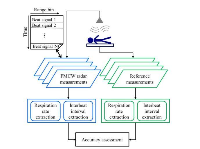
[17] Antikainen, Emmi, Kortelainen, Juha, Antropov, Oleg, Kiuru, Tero, 2020, "Vital Sign Monitoring Using FMCW RadarinVariousSleepingScenarios",Sensors2020,Vol.20
[18]STM,"TheThroughTheWallRadar(DAR)",Accesed: 05.03.2023, Avaiable : https://www.stm.com.tr/en/oursolutions/command-and-control/dar-en
[19] Pasi Koivumäki, 2017, " Triangular and Ramp Waveforms in Target Detection with a Frequency Modulated Continuous Wave Radar ", Aalto University SchoolofElectricalEngineering
[20] Jesse Zheng, 2004, "Analysis of optical frequencymodulatedcontinuous-waveinterference,"AppliedOptics, Vol.43,pp.4189-4198
[21] Lin, JJ., Li, YP., Hsu, WC.,2016, "Design of an FMCW Radar baseband signal processing system for automotive application", SpringerPlus.
[22]Mumtaz,Zeeshan,Hanif,Ali, Hashmi,A.,2015,Digital Signal Processing (DSP) Algorithms for CW/FMCW Portable Radar, 2nd International Conference on Engineering&EmergingTechnologies(ICEET).
[23]Ivanov,s.I.,Kuptsov,Vladimir,Fedotov,A.,2019, The signal processing algorithm of automotive FMCW Radars with an extended range of speed estimation, Journal of Physics:ConferenceSeries,pp.1236
[24] E. Hyun, W. Oh and J. -H. Lee, 2012, "Multi-target detection algorithm for FMCW Radar", 2012 IEEE Radar Conference,Atlanta,,pp.0338-0341.
[25] Mahafza, 2013, “Radar Systems, Analysis and Design usingMATLAB®”,Chapman&Hall/CRC.
[26] F. D. Enggar, A. M. Muthiah, O. D. Winarko, O. N. Samijayani,S. Rahmatia, 2016, "Performance comparison ofvariouswindowingOnFMCWRadarsignalprocessing", "2016 International Symposium on Electronics and Smart Devices(ISESD).
[27] S. I. Ivanov, V. D. Kuptsov, A. A. Fedotov., 2019, "The signal processing algorithm of automotive FMCW Radars with an extended range of speed estimation", "Journal of Physics:ConferenceSeries".
[28] A. Meta, P. Hoogeboom, 2005, "Signal processing algorithms for FMCW moving target indicator synthetic apertureradar","2005IEEE International Geoscienceand RemoteSensingSymposium(IGARSS)".
[29]M.Amarnathan,V.L.Siripurapu,A.K.Chauhan,2012, "Developing A Signal Processing Algorithm For A FMCW RadioAltimeter","IFACProceedingsVolumes",Vol.45,pp. 189-195.
[30] E. Hyun, Y. -S. Jin, J. -H. Lee, 2017, "Moving and stationary target detection scheme using coherent integration and subtraction for automotive FMCW Radar systems," 2017 IEEE Radar Conference (RadarConf), pp. 0476-0481